An internet-connected killbot

Continuing the discussion from Scorbot-ER VII Robot Arm:

To recap the extremely sporadic efforts of getting our industrial robot arm working:

  • @funvill brought it in via friends as a donation to VHS, no strings attached (woo)
  • We have a manual! Digital copy in the linked thread, physical copy next to the control box
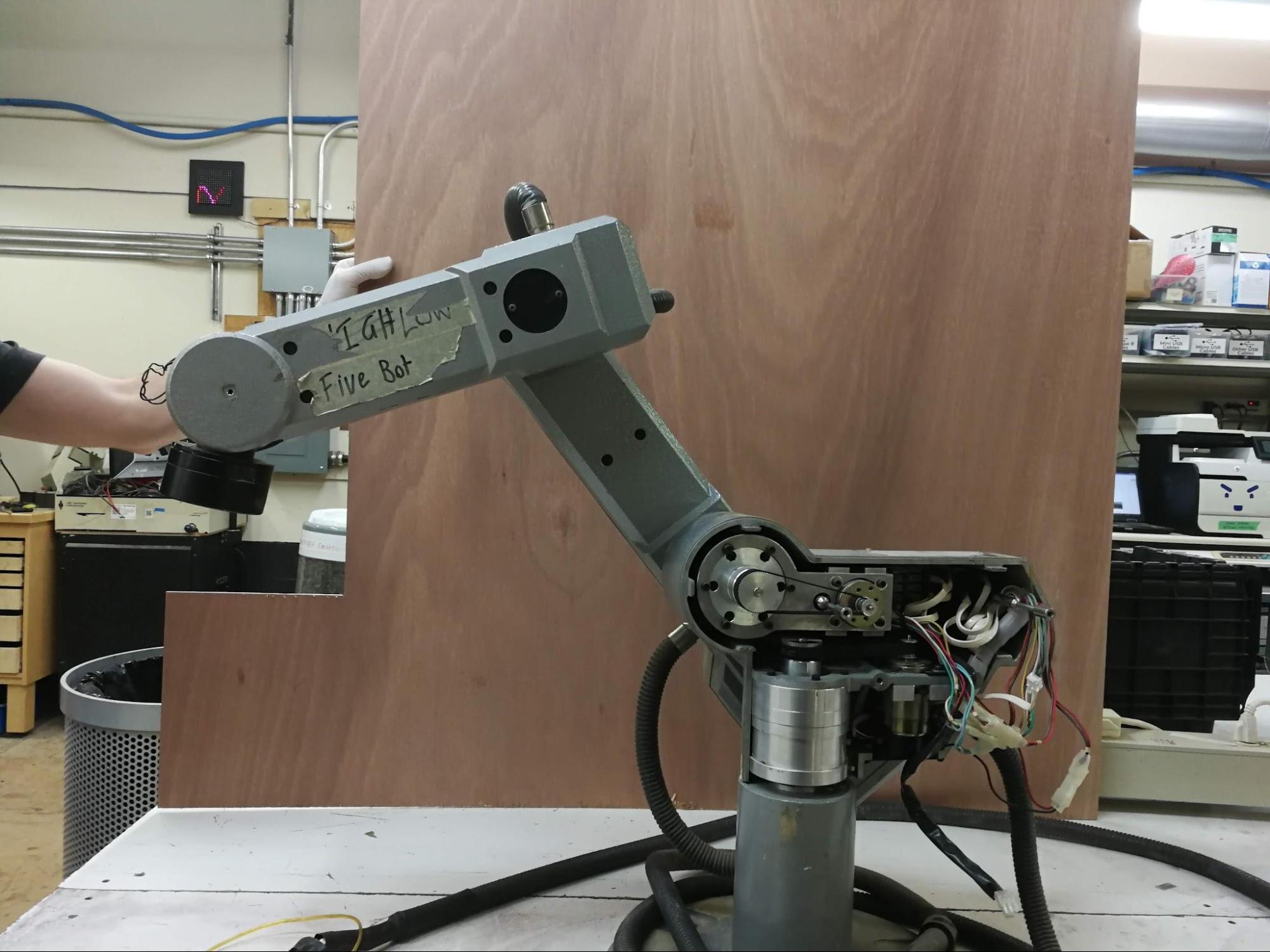
  • It got turned into the High-Five Bot, the official door greeter of VHS
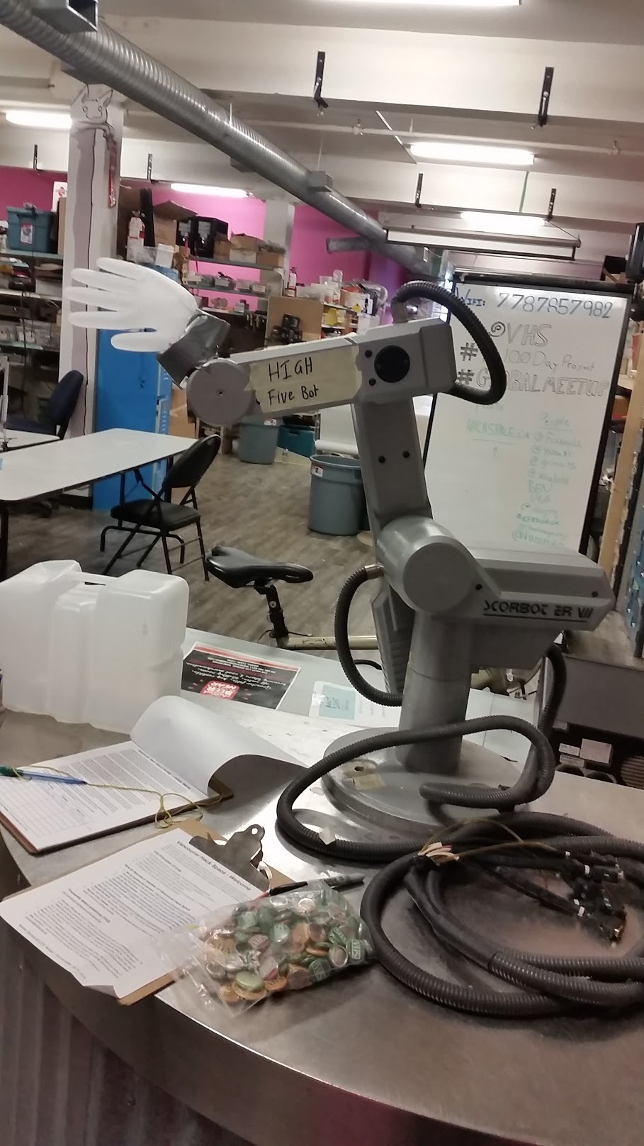
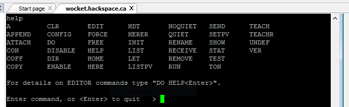
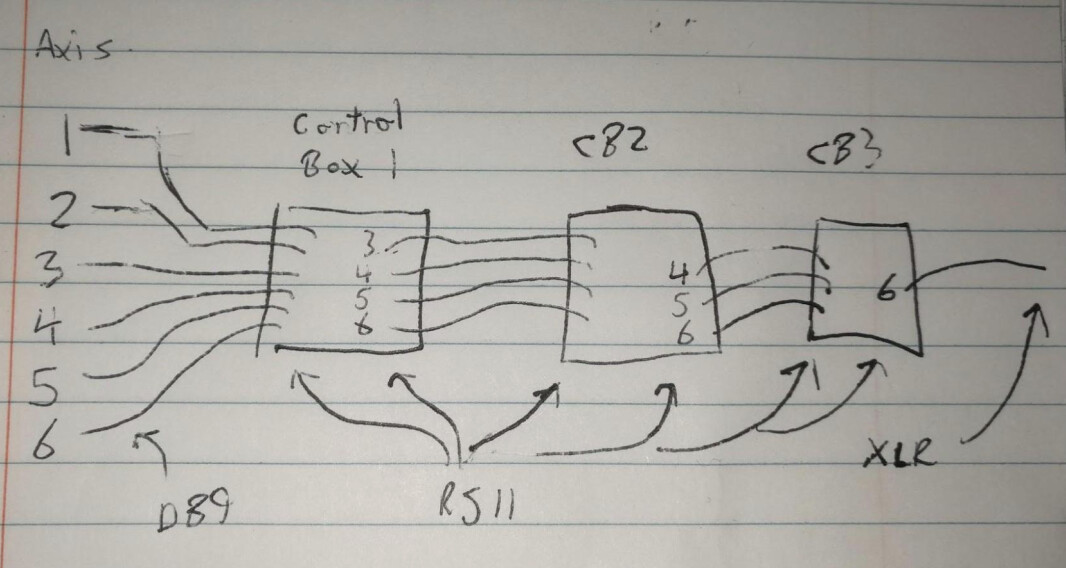
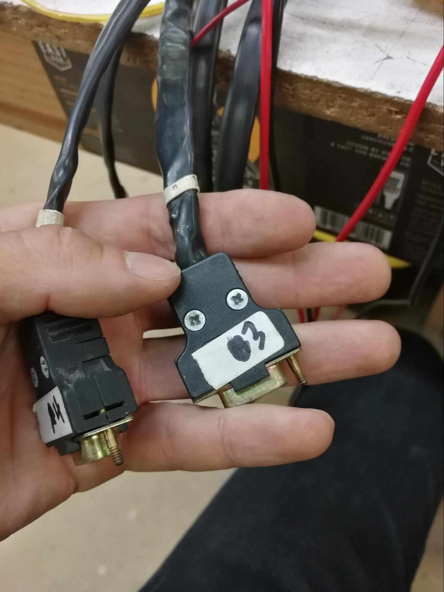
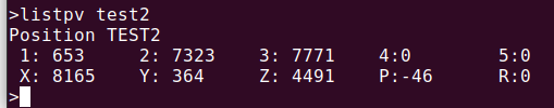
I found a serial connection in the driver, desoldered the connector, and spliced in a proper DB9 serial cable. Then it worked fine with a USB-Serial dongle. Problem is, I did this in January and I don’t remember the settings!

The factory interface a pretty simple command prompt, poorly documented in the manual. “HOME ALL” seems to work, and by that I mean it causes the robot arm to repeatedly slam itself against the table and scare the hell out of everyone in the room.

So I was back at it yesterday, with two goals: Figure out the limit switches, and connect it to the internet. I failed at both, but here’s where I got.

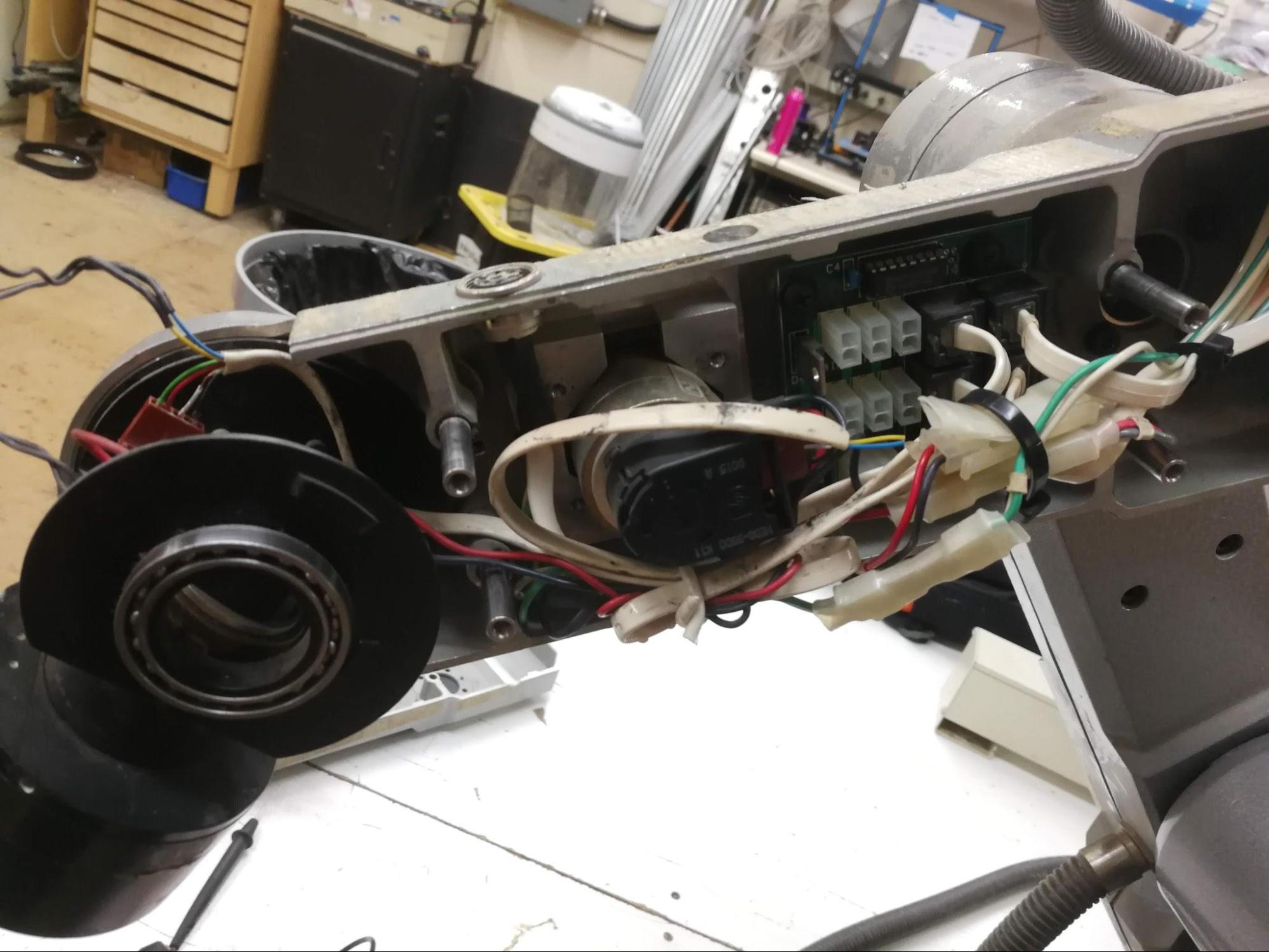
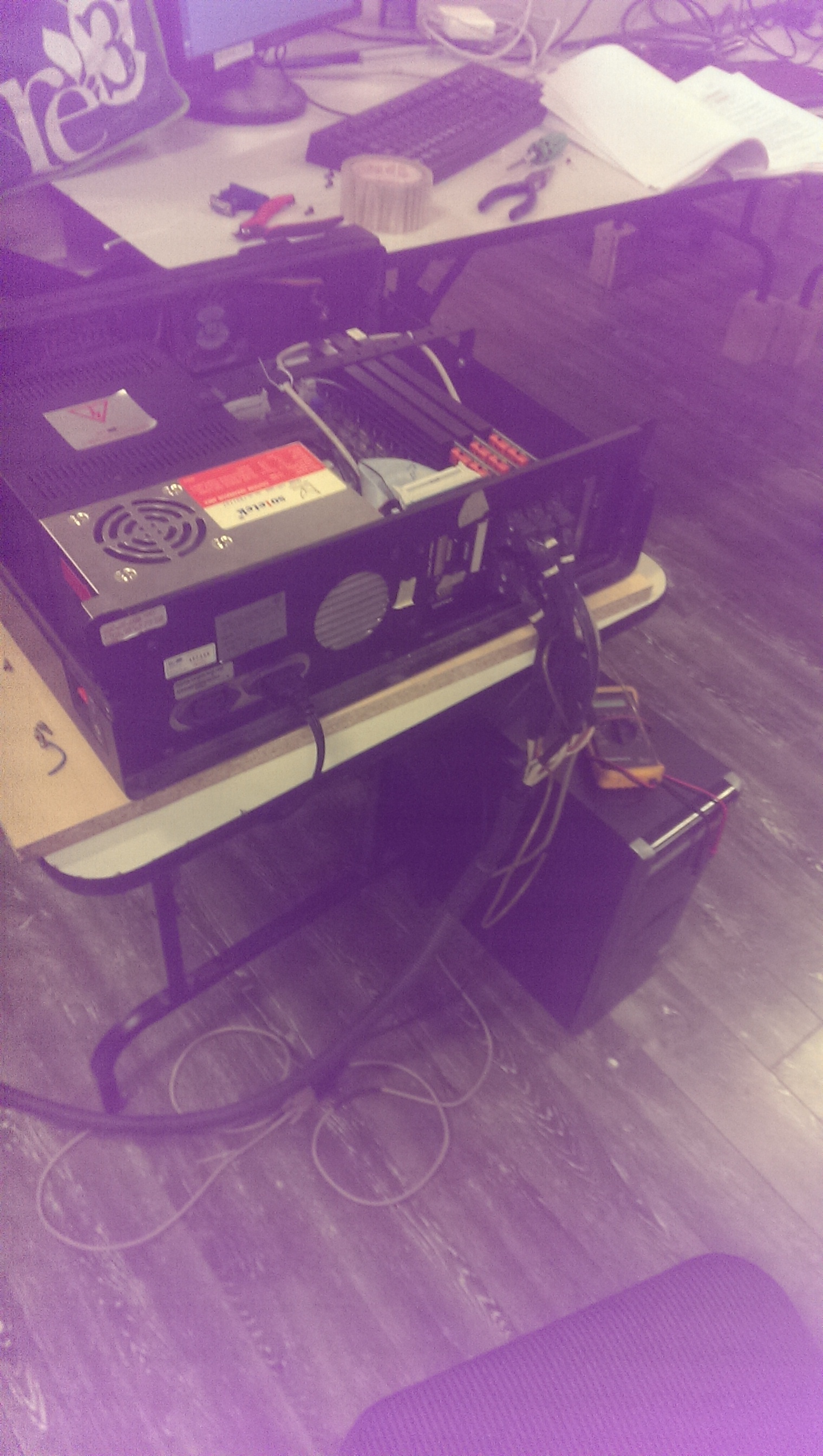
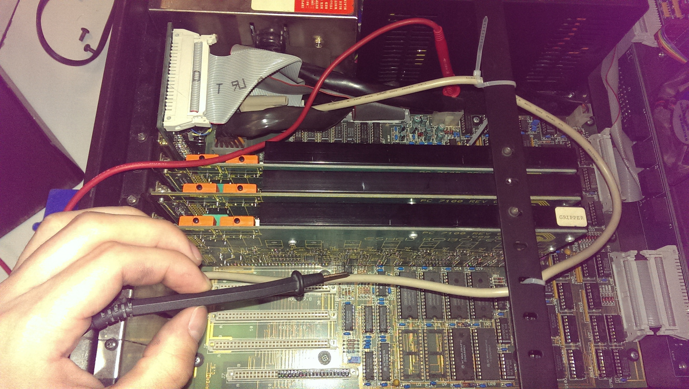
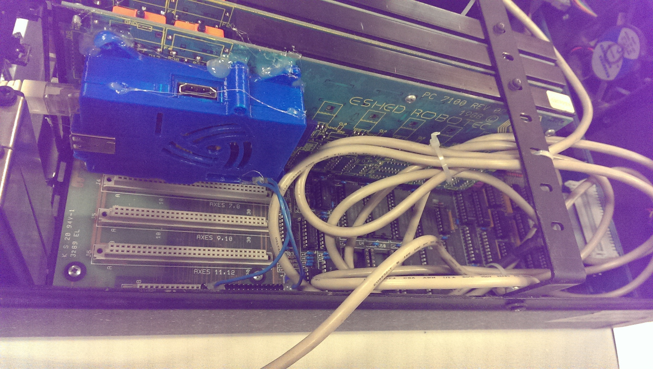
To start with, this is what the controller looks like inside, in all its 80s glory.

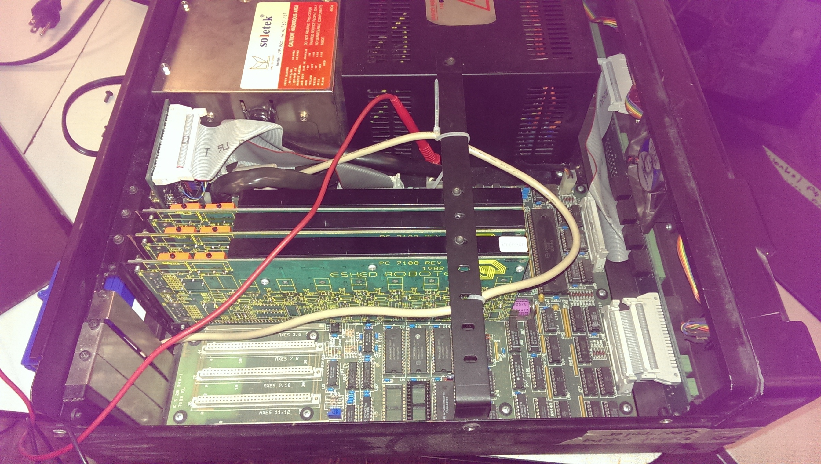
Despite the appearance from the outside, this isn’t a computer in the modern sense of the word at all. You can see the main board on the bottom, all through hole parts, with a huge 6801 microcontroller up in the top right. The majority of the space is taken up by the beefy power supplies in the top, and you can see the expansion cards for each of the robot arm axis with the 1988 copyright year.

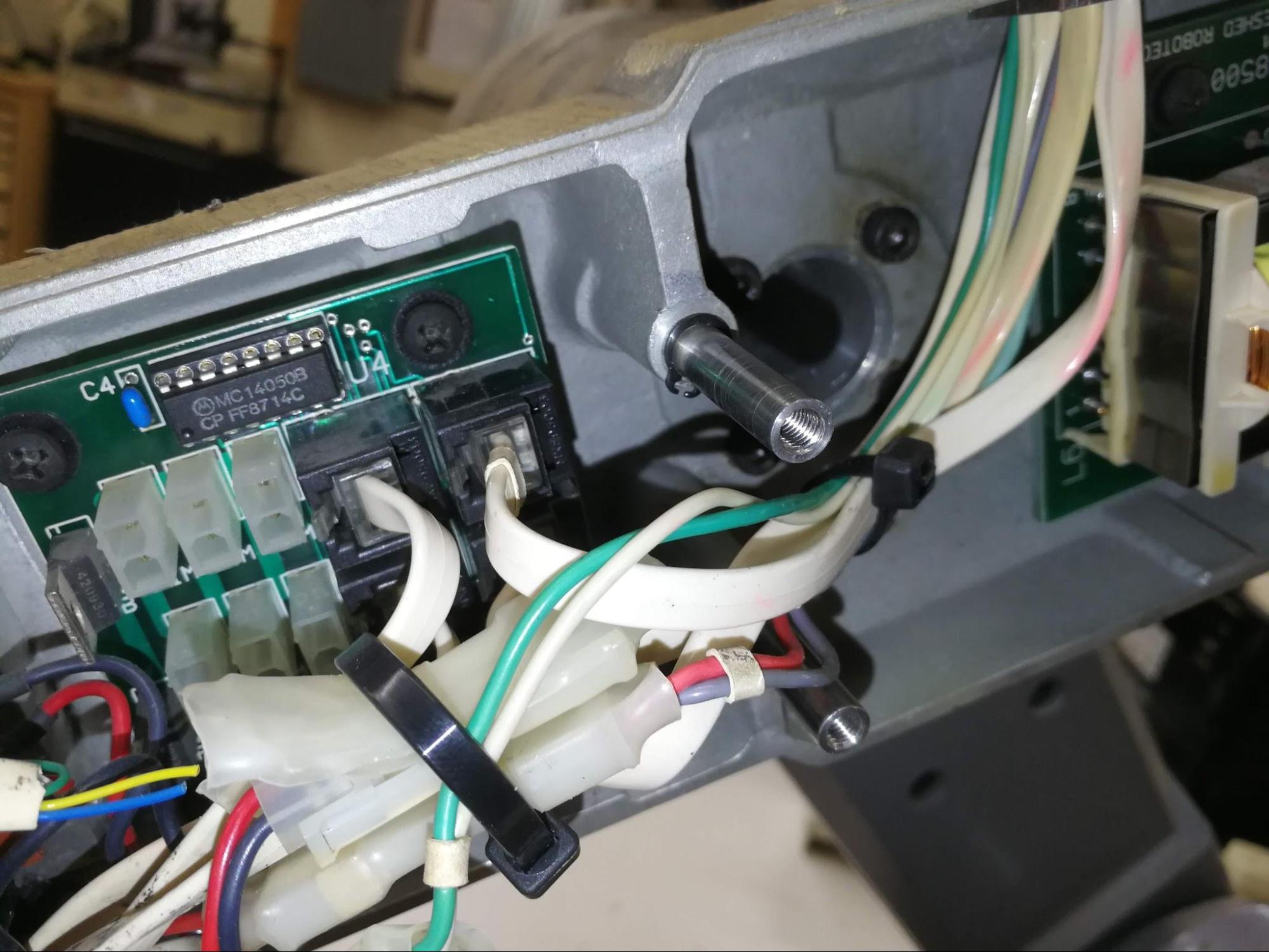
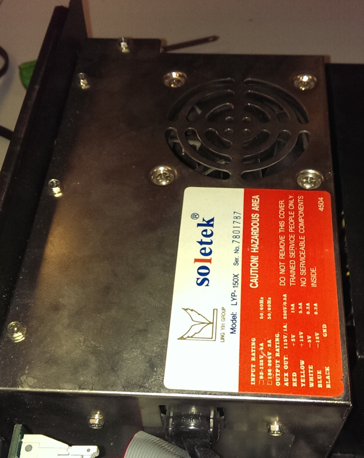
The first step was to find a 5v power rail. Using a sophisticated technique I developed - Reading the label - I was able to find the 5v wires going into the main board from the main power supply.

From there I was able to buzz out the proper pin on one of those unused board mount connectors on the bottom.

And then mount a Raspberry Pi. @Logan_Buchy and @Lukeo I owe you guys one now, I’ll bring it in as soon as possible!

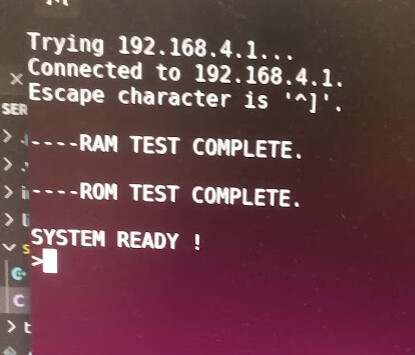
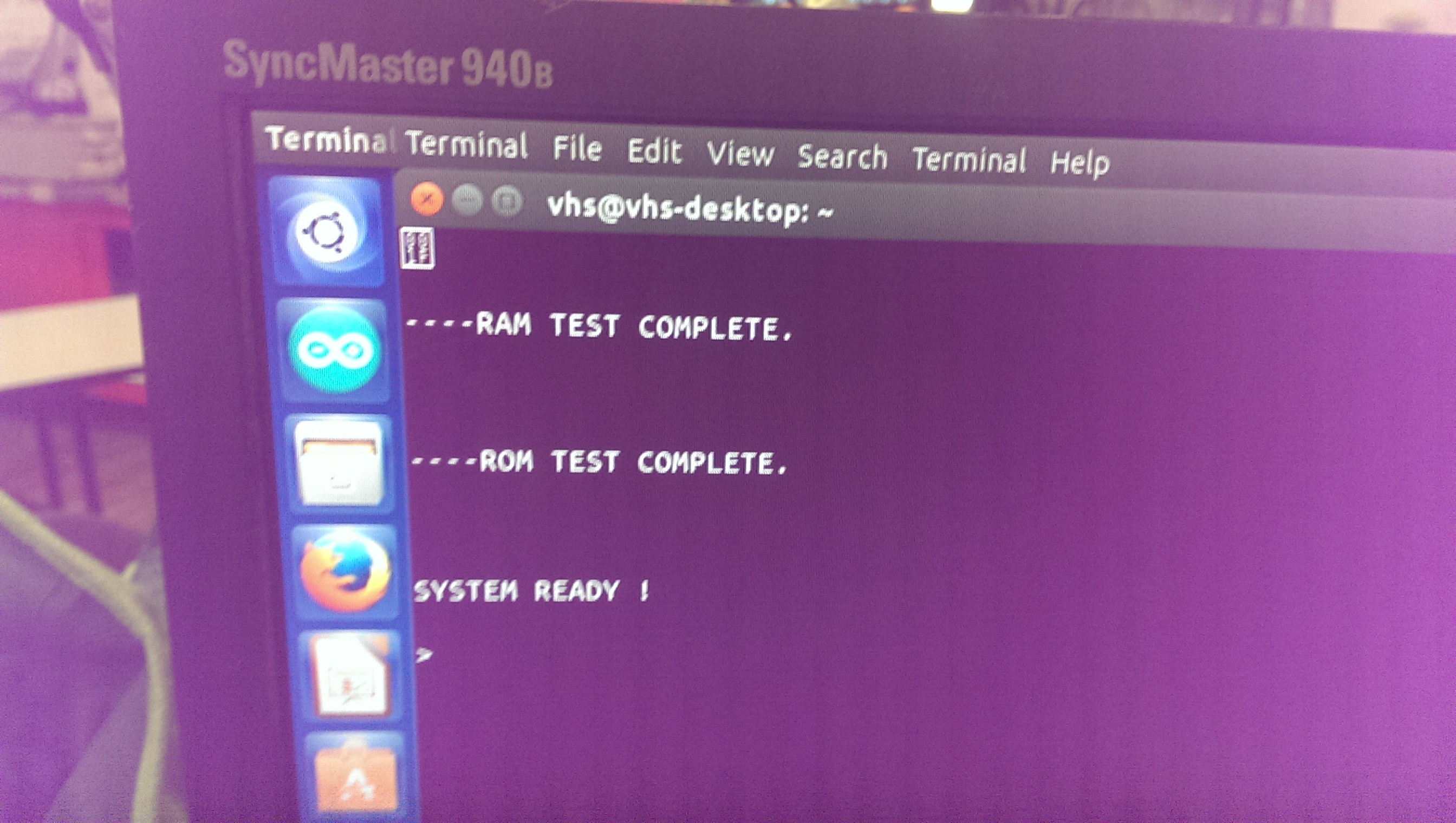
At this point, the RasPi boots up along with the controller, and if you plug an ethernet cable into it, it registers as wocket.vanhack.ca (dunno why) and the credentials are root / dietpi

The serial dongle is at ttyAMA0 I think, and I was trying to get it to work with Minicom, although no luck. The problem could be with my original hacky serial cable fix, using a different dongle, or using the Raspberry Pi. I will have to investigate further!

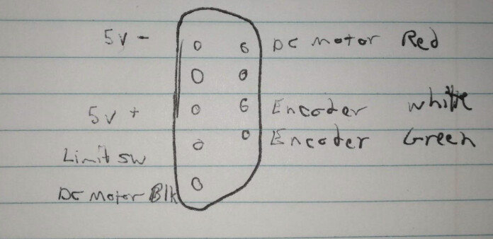
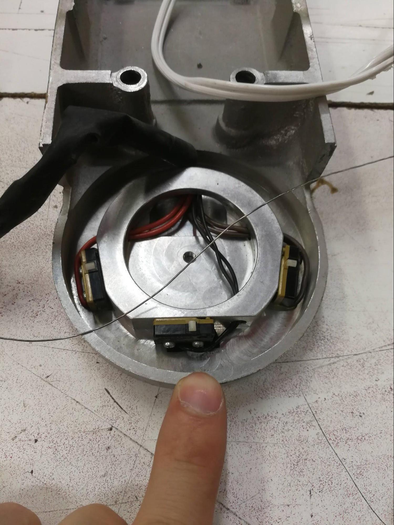
I also didn’t even look at the limit switches.

And that’s where we’re at.

As with any VHS group project, feel free to hack on it and add to this log. I’m not happy until we can reliably get it playing the knife game.

10 Likes

Its called wocket because my theme of naming computers that week was Dr. Seuss.

Great writeup BTW, documentation is good.

3 Likes

Needs more lasers! Maybe a simple one to start with, and then we can mount an industrial one for the knife game?

1 Like

I tossed two usb-to-serial adapters into the case.

1 Like

Thanks, dude!

Works, using a different USB dongle provided by @toma

After SSHing in, type minicom --device /dev/ttyUSB0 and then help to see what’s up.

image

Because I expect this RasPi to be turned on and off nastily directly at the power switch a whole lot, does anybody have experience with locking the SD cards of these things to prevent corruption?

There’s a boot script at /DietPi/dietpi/boot that I’m considering adding the above command to, and then locking everything down. That’ll allow you to SSH directly into the controller’s terminal, without dealing with any of the Linuxy stuff.

2 Likes

Nice work! I’ve been enjoying reading about the progress.

AFAIK the read-only switch on the SD card is advisory only, so it basically does nothing. To prevent corruption you have to plead with the system to not write anything to the SD card (or at least not very frequently).

I used to remount the filesystems read-only with Raspbian, but honestly since switching to DietPi for these sorts of things, I just don’t really worry about it anymore. So far it hasn’t bit me. DietPi has a ramdisk log thingy, so make sure that’s enabled. It remounts /var/log as a ramdisk thus making it ephemeral, which is fine.

Great idea. If you do that and disable most of the unneeded services, the risk of corruption is probably really really low. Maybe take an image of the card just in case.

1 Like

Yup! Tons. The thing about SD cards is they already have their own flash translation layer (FTL) built into the microcontroller’s firmware. So corruption at the flash layer isn’t something you need to worry about.

However it still is possible to corrupt the file system residing on the block layer. A modern journaled file system like ext4 is very resilient to hard power down of the device - trust me, I spent a good few months beating the crap out of all the SD cards on the market (many are shockingly bad). Just make sure journaling is actually on (it is by default on ext4).

At a low level this is true. The switch isn’t electrically connected to anything, it’s supposed to trigger a switch inside the slot, and the driver or SD controller IC should suppress any writes. I’d expect the Pi’s Linux drivers to be properly behaved when encountering a read-only SD card, but the only way to know is to test it.

You need an OS designed to run from read-only storage for that to actually “work” though…I’m not familiar with any designed for this purpose that work on Pi other than OpenWRT - which might be a very viable option.

Love this project. I guess G-code would be the “modern” way to control such a robot?

One of the ways, I think you can often just use a pendant to train them.

On a more DIY setup, you can set up custom kinematics in LinuxCNC, basically you just have to tell it the mathematics of each “joint” (motor), and how they interact with the Cartesian coordinates of the end effector. Overview here: Kinematics

Bit of a pain to set up (especially if there isn’t already a kinematics module for your setup) but really cool when its working. You get to treat the machine the same as a gantry mill.

1 Like

So we don’t have a pendant. The manual has a large section devoted to it, but we don’t have one.

I don’t think that’s a bad thing, they’re usually used in industrial settings for a trained robot arm wrangler to teach it a simple task that it will be repeating on an assembly line.

That doesn’t really apply to us, and most of us can do some form of programming. I did a bit of research yesterday, so I can talk a little more about that.

Our controller uses “ACL”, or Advanced Control Language. The commands work in the terminal, but they are not represented in the help menu.

For example, you can type show din to display all of the digital inputs, which is a controller command, and shown in the help menu. It will usually return 16 zeros.
After you type lson though, an ACL command and not in the help menu, two of those bits flipped on.

Exciting stuff! Presumably those are supposed to be limit switches, but in our brief test, @Shane and I weren’t able to make any more bits (including those) change.

Here is some more reading on our particular model:
http://web.csulb.edu/~wmartinz/robot/scorbot/manuals/Scorbot_Intro%20VII.pdf

There should also be some dedicated ACL reference manuals that I haven’t looked for yet.

I believe the controller also has a kinematics solver built in. Haven’t looked at it in detail, yet.

2 Likes

ACL reference guide I found…

http://195.130.93.18/pachidis/robotiki/index.files/100083-a%20ACL44-Ctrl-A.pdf

Over the years, I’ve opened this up a handful of times to slowly fix it up. Let’s document how it works a little bit better.

Here’s the thing.

Axis are 1-6, from bottom to the end.

1: Side to side rotation

  1. Up and down of the shoulder

  2. Up and down of the elbow

  3. Up and down of the wrist

  4. Rotation of the wrist

  5. Not populated! This goes to the connector on the top, and can be used for an end effector. We don’t have one, but we could build one.

The control box for axis 1 and 2 is a bit packed and hard to work with.

Axis 3:

The box for axis 4, 5, and 6 is the easiest to work with.

Each control box (there are three) consists of:

RJ11 connectors coming in, one for each axis.

RJ11 connectors going out, for only the downstream axis.

ATX-style connector coming in from the associated axes limit switches.

Two diodes for each motor.

A buffer chip (MC14050B) for the limit switches and quadrature encoders.

Each control box is daisy chained to the next one using the RJ11 cables.

The cables coming out used to be improperly labelled. I fixed that.

They are wired up to DB9 connectors like this:

Applying 5v to the 5V+/5V- lines powers up the optical encoders and buffers. The buffers send the encoder and limit switch data back to the bottom. The encoder is a HEDS-5500, which is pretty straightforward. I didn’t snap a picture of the limit switches in detail, but they’re pretty common form factors, and I replaced a bunch that were dodgy back in 2018.

The way the axis 4 limit switches (mounted to the cover) work is the middle one (black wires) is Normally Open. The outer two (red and brown) are Normally Closed.

The mating feature has two cams machined into it.

Throughout the entire valid distance of travel, the long cam is engaging the middle limit switch, keeping it closed. At either end of the travel, the small cam engages the side limit switches, opening them up. At the control PCB, these are all wired up in series, so a “closed” signal is valid travel, while an “open” signal means that one of the end stops has been hit, or it’s not in the valid range of motion for some catastrophic reason.

I haven’t yet investigated how the other axes work, but given what we now know, it’s possible to investigate without opening up the machine.

It’s clear from the PCB that the design intent is that the motor cables are wired through the endstops as well, and through diodes in a clever way where if you hit one of the endstops, the motor can only move in the opposite direction. Weirdly, though, this has been bypassed by the previous owners. I’ll leave that for now, but I’m tempted to fix it. The software should handle that, though. This is just an extra failsafe.

That’s what all these extra dangling white connectors are, and they’d normally instead be plugged into the upper white connectors (in and out).

That’s pretty much it. There are some transformers throughout, and I am completely baffled as to their purpose. They’re not wired up to anything.

With all that, I don’t believe it should ever be necessary to open the thing up again, unless something breaks.

Next steps are to plug the controller in again and play around. The Raspberry Pi and RS232 dongle have gone missing, so I’ll have to hunt around for more. I’m also somewhat tempted to build my own controller, but it could be a three hour job to figure out the existing (slightly annoying) controller vs. probably 20-40 hours for unnecessarily rolling my own.

So, given that we’re totally connecting this thing to the internet, what does that look like?

6 Likes

Is there an off the shelf controller we can buy to make the project easier. We have another robot arm that could use a modern controller as well. so we can get rid of the computer from the 1980 that is currently running it. This way, lesson learned from one can be applied to make the next project easier.

1 Like

Nothing that can be done in less than three hours, for sure.

One possible way forward is to drive it with LinuxCNC. There is a SCARA kinematics model for LinuxCNC.

Requirements:
CNC driver board with five axes that can drive 12V DC motors (ie. it has an H-bridge), have an optical encoder input, and a limit switch input
A computer with monitor (or some sort of clever network setup)

I’m not really sure that’s better. More modern, certainly.

I haven’t looked at the other arm, so I don’t know if it’s compatible, electrically, at all.

Nice hardware. It’s a solution in search of a problem.

It could use a conversion to CANbus … simplify the wiring and much easier(cheaper) to control.

Instead of making a new thread, I figured most of the people who would be interested is here already:

“Hello all,
I have been contacted by a company looking for individuals familiar with ROS2, passionate about education and creating curriculum for K-12 and college students. They would like to send people a new robot platform to serve as beta testers and give feedback on the platform as well as curriculum. If interested, please respond to me and we will try to schedule a meeting with the company on 10/5 or 10/12.
Thanks.”

From Dr. Carlotta A. Berry, berry123@rose-hulman.edu

Controller updates:

I’ve got it wired up to an ESP32 and broadcasting a wireless access point. Oh yes, this is happening.

The original link to manual is dead, fortunately I had a backup:

https://drive.google.com/file/d/1trtBA94W2yk28AAeP3zh1h-aWIW61NgR/view?usp=sharing

Details for the RS232 pins on the big DB25 port on the back:

image

So I bypassed that and used a MAX232 to get it talking to an ESP32. WE DON’T NEED TO LOOK AT THAT WIRING JUST NOW!
I will clean it up, I swear.

The ESP32 is running this firmware:

Only the SSID and baudrate (9600) are changed.

To connect to it from another computer connected to the AP:
> screen telnet 192.168.4.1 8881

image

Oh hay.

There’s a university course that covers this, I guess, it has some tips for using the menu system.

There are some parameters that are stored in memory, and I am terrified of this 35 year old controller releasing its magic smoke and/or letting all the bits fall out. So here are the parameters and the values I pulled from them:

33: 23040
34: -15000
35: 23040
36: 28800
37: 9600
52: 0
53: 11756
54: 9160
55: 734
56: 2142
92: -353
93: 500
94: 3585
95: 3000
96: 2500
97: 2510

Now I don’t have this currently connected to the killbot, but future-me, this is what I think I need to do:

UNDEF TP1
UNDEF TP2
HERE TP1
<move axis by hand>
HERE TP2
LISTPV TP1
LISTPV TP2
<check that the values make sense and clear the area>
CON
MOVE TP1
MOVE TP2
COFF

Points are stored as both axis encoder steps (1-5), and XYZ, pitch, and roll of the end of the (nonexistent) gripper.
image

8 Likes

So cool.

For those of us mere mortal who are not in tune this this divine language, what can the arm do now?

I would really love a demo of the arm and to be taught how to interact with it.

1 Like

attaching plasma cutter when?

3 Likes