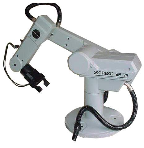
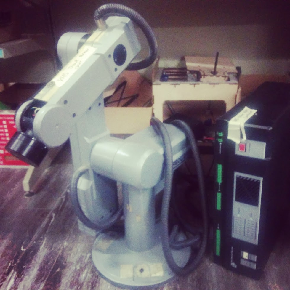
VHS got a donation of a Scorbot-ER VII Robot Arm from a friend of mine. Its a donation to VHS and has no strings attached. It was “working” when it left his office but its been storage for a long time. The robot arm also comes with the controller. I have no idea how any of this works.
Would anyone like to play with it? Its open for anyone.
Just be careful, a robot arm can be dangerous. Don’t activate it while within its working area.
Have fun.
Of course, the robot arm must have a work cell around it, of about a
meter in radius, which nobody should enter while it is operational.
It can easily break bones if it suddenly moves at full speed with
someone in the way.
According to the manual, it should just be a PWM servo output, so reasonably easy to reverse engineer. Probably not the same kind of servo control that we’re used to, but we have the tools to figure it out.
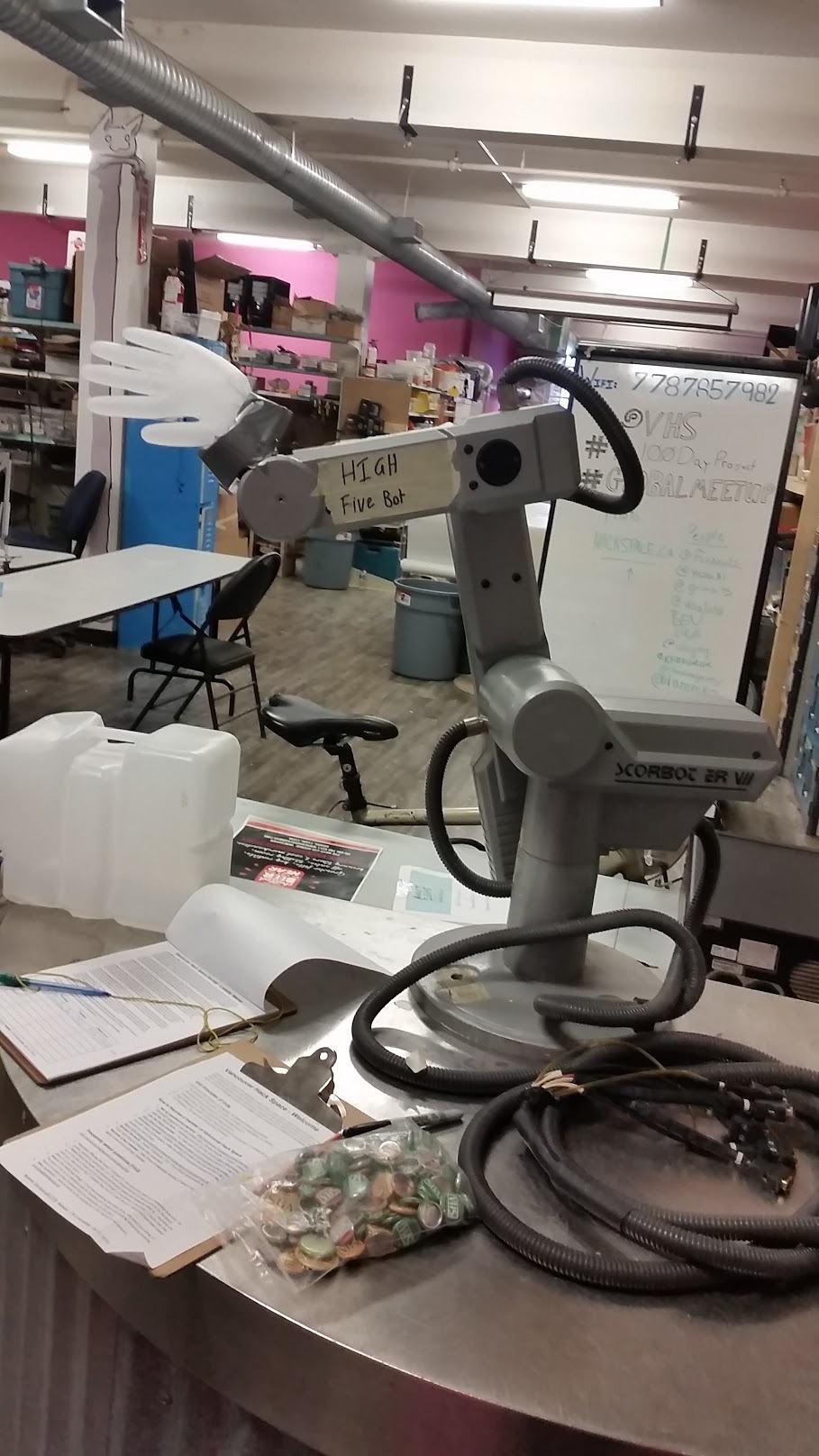
Let’s take things a step at a time. First, figure out how to use it and confirm that it still works, then decide what sort of work surface and perimeter it needs. You can’t un-drill holes and it’d be a shame to ruin that surface just for the High Five Bot.
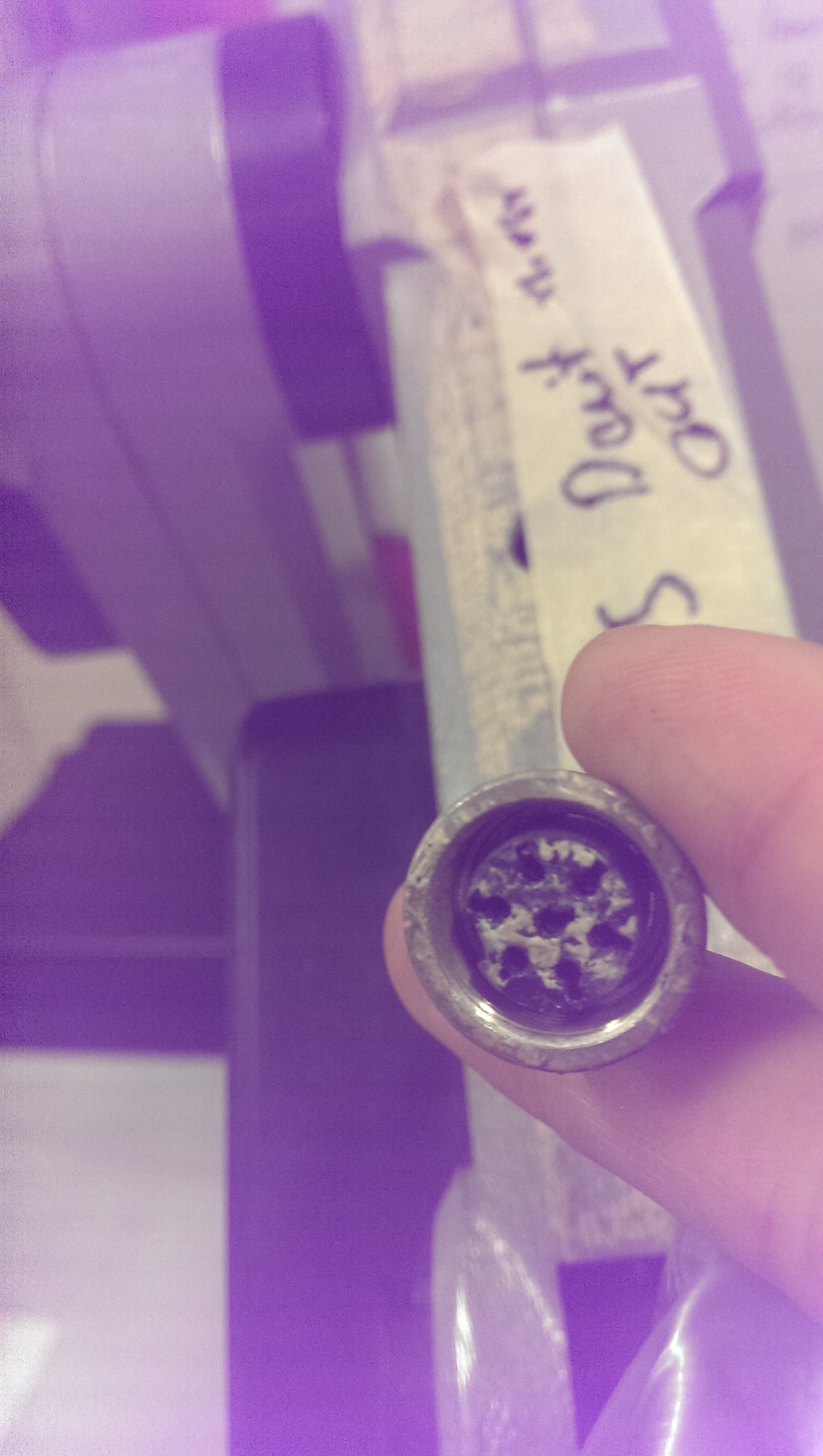
Take a look at it, it’s in a drawer below the robot itself. I haven’t
looked into talking to the control box, but it might be easier than driving
the motors directly. It looks like some form of simple movement commands
sent over RS232.
@Jarrett: Hmm, that would have been handy to know… Lol, oh well, I’d like to make something from scratch. I’ll use it as a reference for signals if I need to.
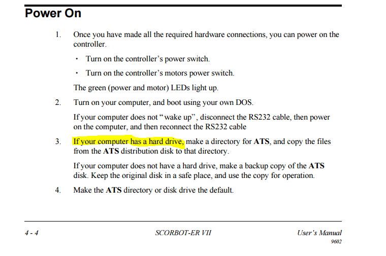
I was looking at it last night the driver seems good, while reading the software I had a moment of realization on just how old this thing is, copyright 1996, 1998 for the manual the driver wants to be booted in DOS and the manual has instructions in case your computer does not have a hard drive so perhaps bypassing its original user interface would be better. that being said their is 16 input buttons on the front of the driver so I think running its original software on a computer to “home” it then controlling it with an arduino set up through the input ports would be the fastest path to success
In case you need more, I donated nineteen L293D Dual H-Bridge (Quad Half H-Bridge) driver chips to VHS, and they’re probably all still there in the components section. The tray is labeled and I think it’s either on the top right or bottom right of the inner wall.
Notes: The base, shoulder and elbow motors require more than 1.2A to move smoothly (or counter gravity), a driver with greater current than the L293D is needed. The wrist and rotational wrist motor will also need greater current for reliable performance.
Another update: @Logan_Buchy’s suggestion was a good one, a single L293D in parallel is enough to reliably drive the wrist motors, it can move the elbow against gravity, but just barely. I’ll be trying some beefier H-bridges tomorrow night or on Tuesday.
Notes: Wrist motors are probably fine with 1.2A and a 2.4A peak current driver. Elbow, shoulder and base motors will need at least 3A, if not 4A. All of the drivers used will need heat sinking, changing direction causes a peak that heats the drivers a fair bit.