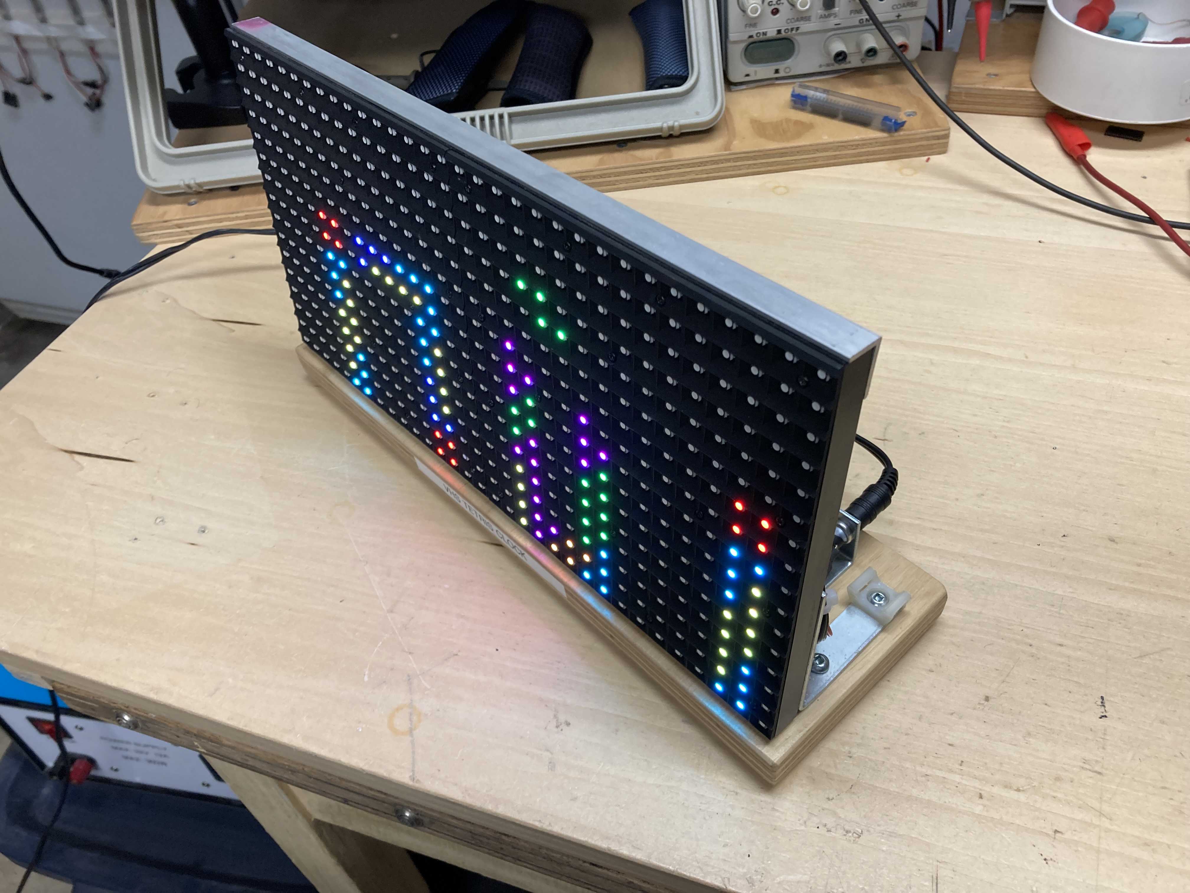
Here is another project for the VHS RGB LED panels. This is a digital clock with Tetris style animations each time the digits change (every minute). It gets it’s time via a Internet time sync (NTP) so it needs a Wi-Fi connection but at least it will always be accurate.
In order to make a VHS Pixel Panel you will need the following:
- VHS RGB LED Panel (2 of them)
- Short LED Panel Jumper (in same box as LED panels)
- ESP8266 Module (NodeMCU, WeMOS, etc)
- Female to Female Dupont Jumpers (30 cm long)
- Misc wire to connect power supply
- 5V 1A power supply
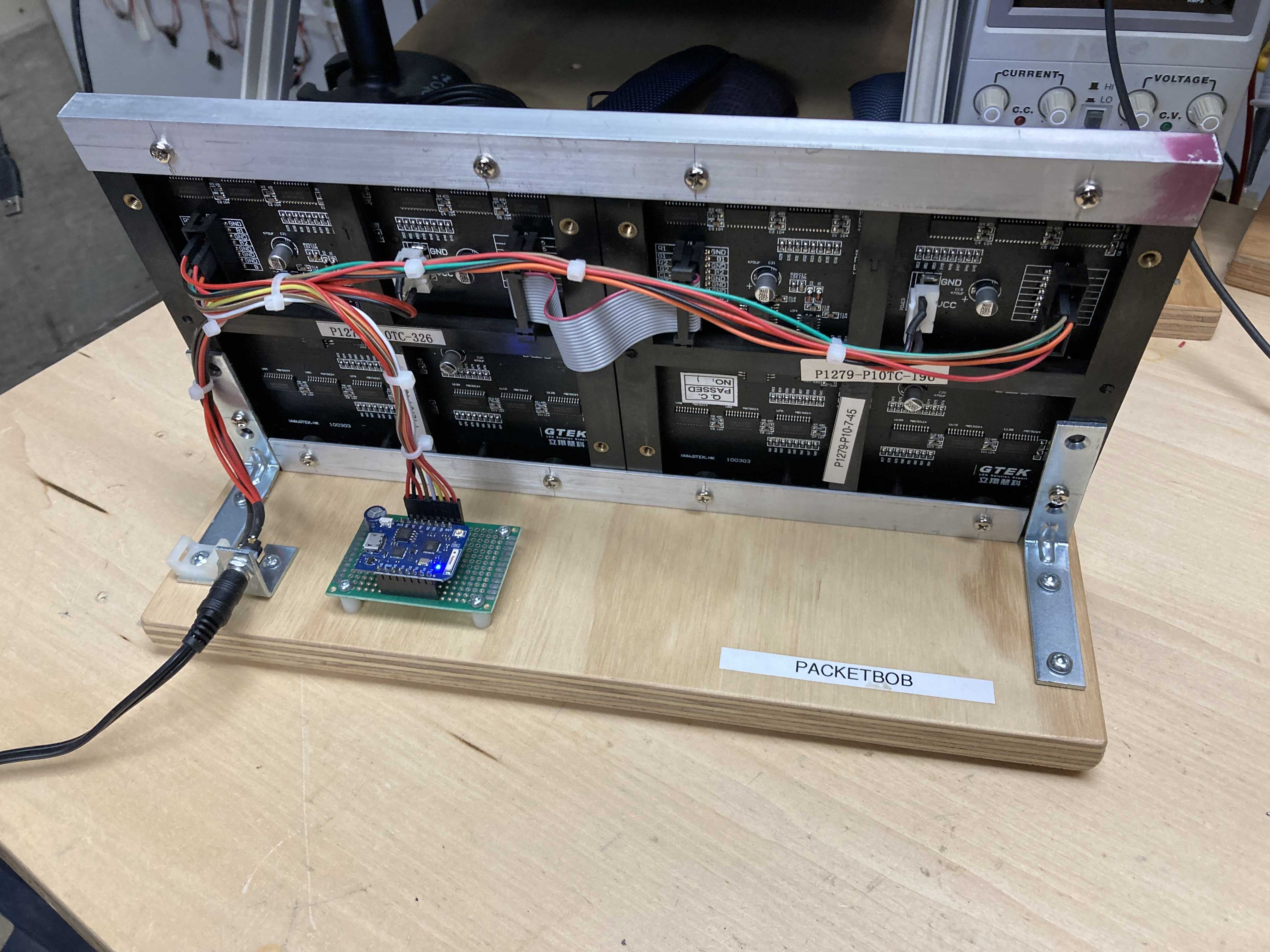
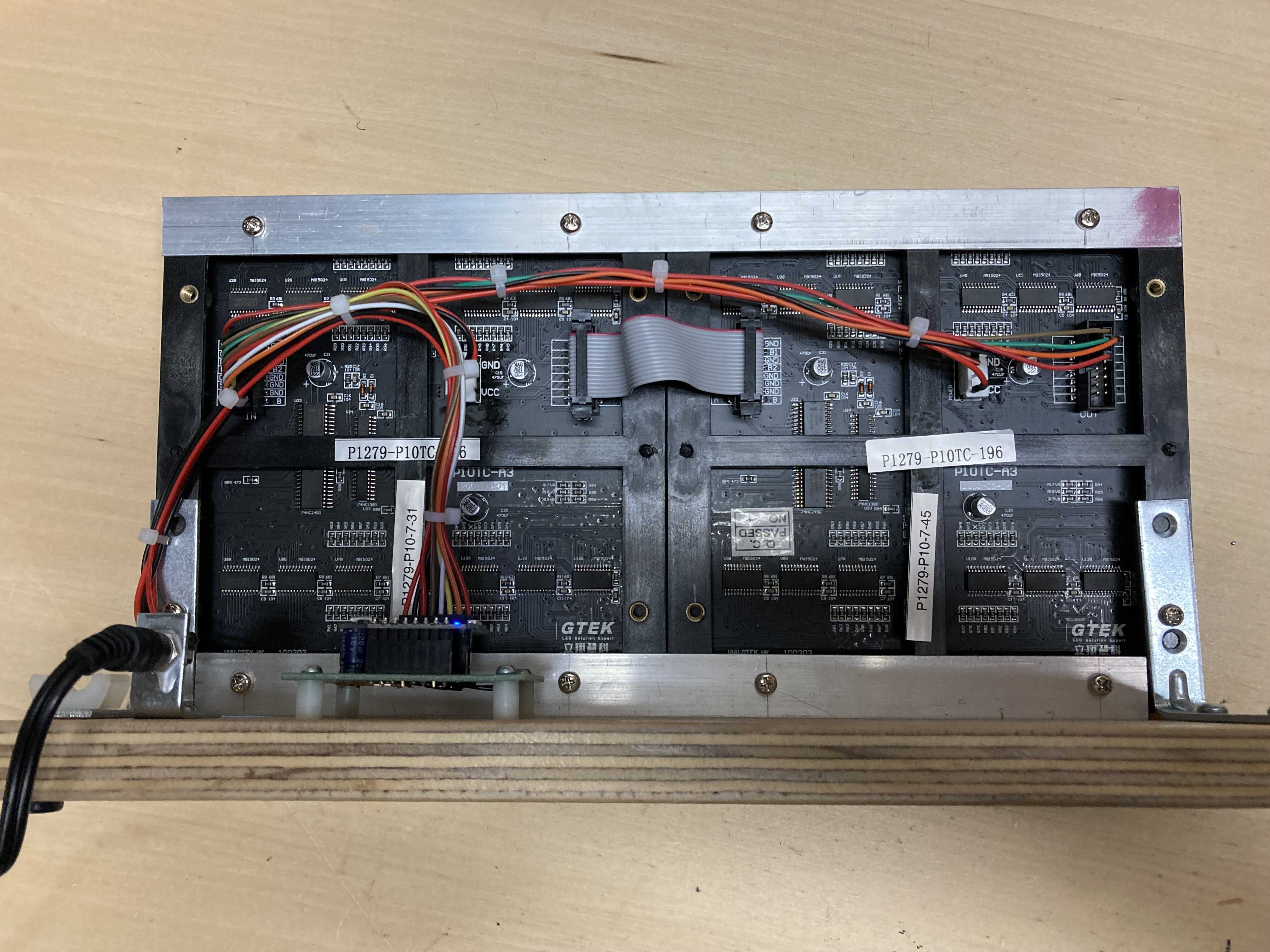
The build is similar to the previous one except that we have 2 panels connected together.
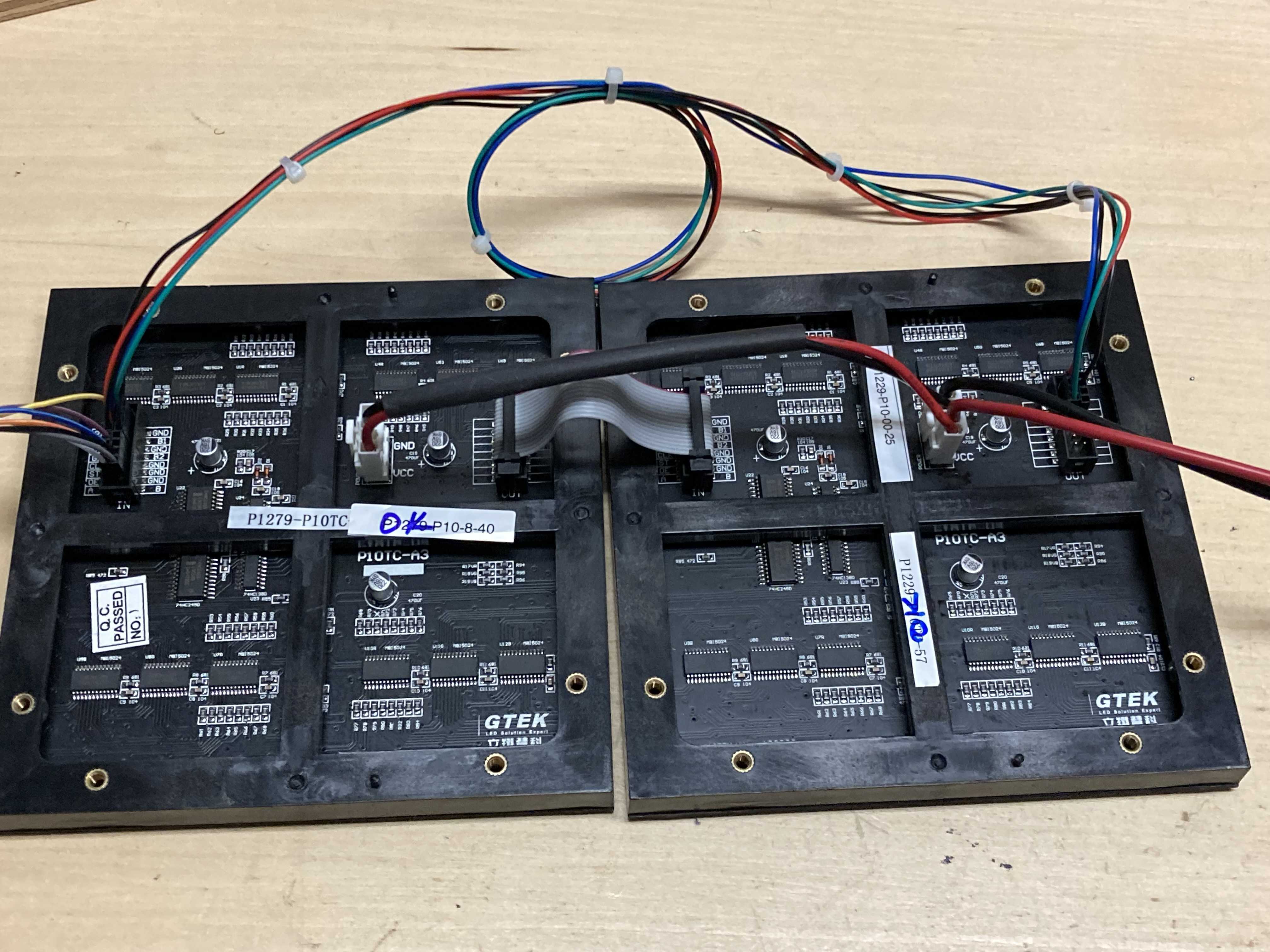
First you need to use one of the short LED panel jumpers cables (you will find these in the box of LED panels) to connect the OUT from one panel to the IN on the next…
Then connect the IN pins from the first panel to the OUT pins on the second panel as noted:
| P10 Panel IN/OUT Connections | |
|---|---|
| IN Pin | OUT Pin |
| R2 | R1 |
| G1 | R2 |
| G2 | G1 |
| B1 | G2 |
| B2 | B1 |
| You will need 30 cm long jumpers for this (in my example I used some really long ones that I had) | |
|  |
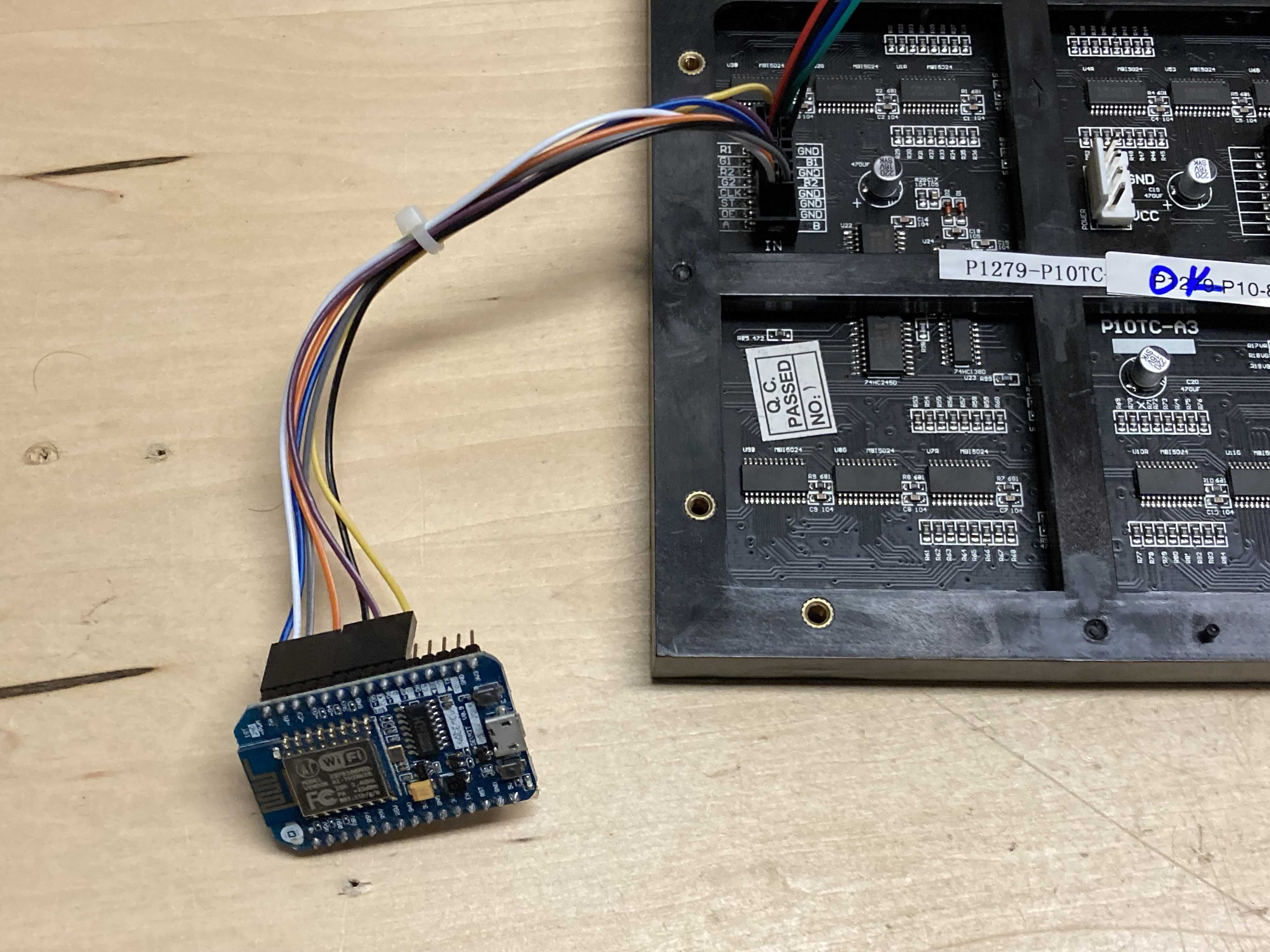
Then connect your ESP8266 module as noted below:
| ESP8266 Board Header Pinout | ||
|---|---|---|
| NodeMCU Pin | Description | P10 Pin |
| D0 | Latch | ST |
| D1 | A Address | A |
| D2 | B Address | B |
| D4 | Output Enable | OE |
| D5 | Clock | CLK |
| D7 | Data | R1 |
| GND | GND | GND |
And you will need power for the two panels. I used some power supply cables (available in the storage box in the furnace room, see notes in this post VHS RGB Panel Project # 1 (Panel Tester) but you can solder directly to the pins.
Remember to supply power to the ESP8266 module also. I used a 5V 2A power supply for the one I built.
Now for the software…
You also have to have the ESP8266 core support added to your Arduino IDE:
Download the code and open in your Arduino IDE
VHS_Tetris_Clock_v1.2.zip (6.1 KB)
The code is completely based on this:
It was released for use with Visual Studio Code and the PlatformIO Arduino addon. I just pulled out the source code so you could use the Arduino IDE. Make sure you install the required libraries. I have had issues with the various libraries conflicting on one of my PCs but it complies fine on another. Let me know if you have issues.
Upload the code to your ESP8266 module and when it initially reboots you will see nothing…
As it has no Wi-Fi credentials setup it will boot into AP mode. Using a laptop find the SSID called “VHSTetrisClock” and connect usign the password “vhstetrisclock”.
Then fire up a browser and connect to this IP “192.168.4.1”. You will get a page with Wi-FI connection options. Select “Configure Wi-Fi” and you will see the available networks you can connect to. Select yours and enter the password. The module will reboot again and shoudl connect to your Wi-Fi. Within a minute or two it should start displaying the time. If you have issues you can connect to the ESP-8266 module via a USB cable and use any serial terminal (set for 8, N, 1 & 115200 bps) to look at the logging.
Please note that you will not get any display if you don’t get a NTP lookup via a working Wi-Fi connection that has Internet access. There is no RTC (Real Time Clock) to keep track of the time should it not get NTP data. This would be nice to add if you want to muck with the code.
If you move the clock away from the configured Wi-Fi network it will revert to the AP mode and you will need to access the SSID (as mentioned above) and reconfigure to the new network.
Here are some pictures on the one I built for the Space