We have a fair pile of tested (marked OK on back) and working 16x16 RGB LED panels available for projects… These are in a box in the LED rack (next to Ecycling shelf). The cost for each panel is $5.00
You can either drop cash off in the donation drop box or eTransfer to the Space…
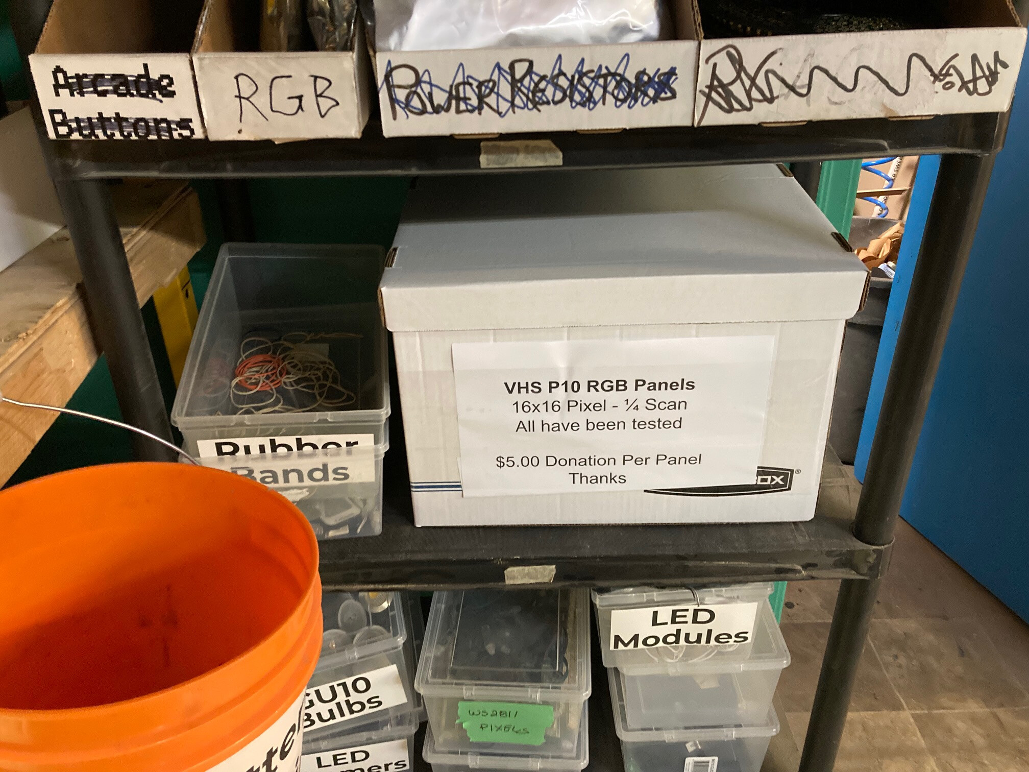
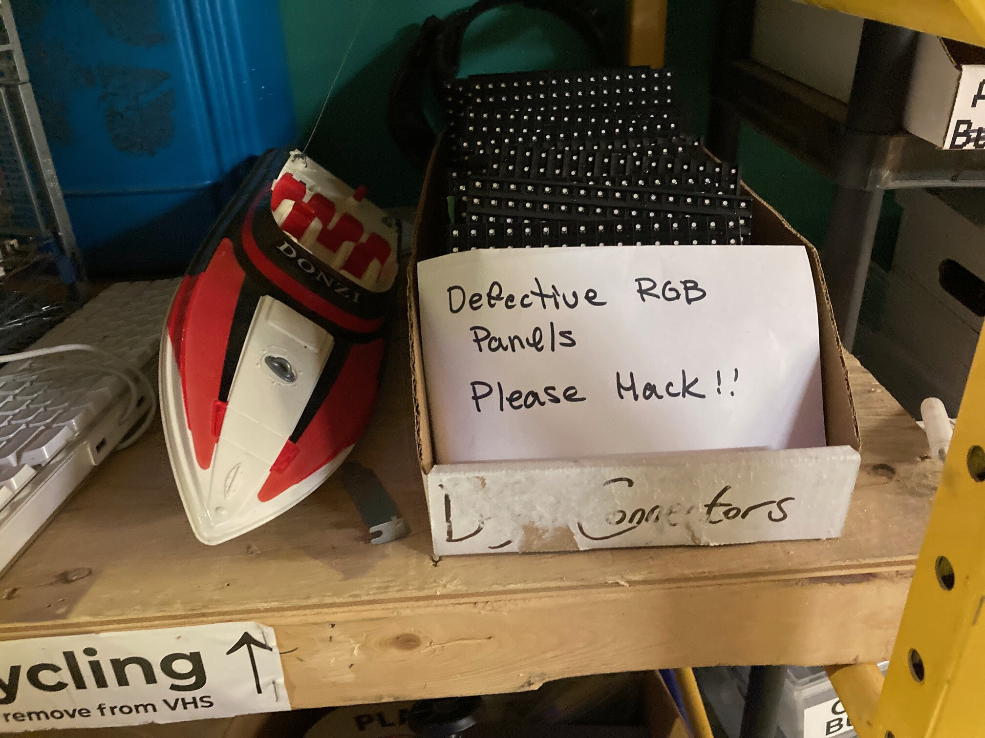
We also have a smaller pile of defective ones (marked BAD on back) in the Ecycling/UpForGrabs area should you want to try resituating them…
In order to make use of them you will need the following:
- ESP8266 Module (NodeMCU, WeMOS, etc)
- Female to Female Dupont Jumpers (at least 12)
- Power supply for ESP8266 (Cell phone charger is fine)
- 5V 1A power supply for RGB Panel
You also have to have the ESP8266 core support added to your Arduino IDE:
Here are the connections on the back of the panel
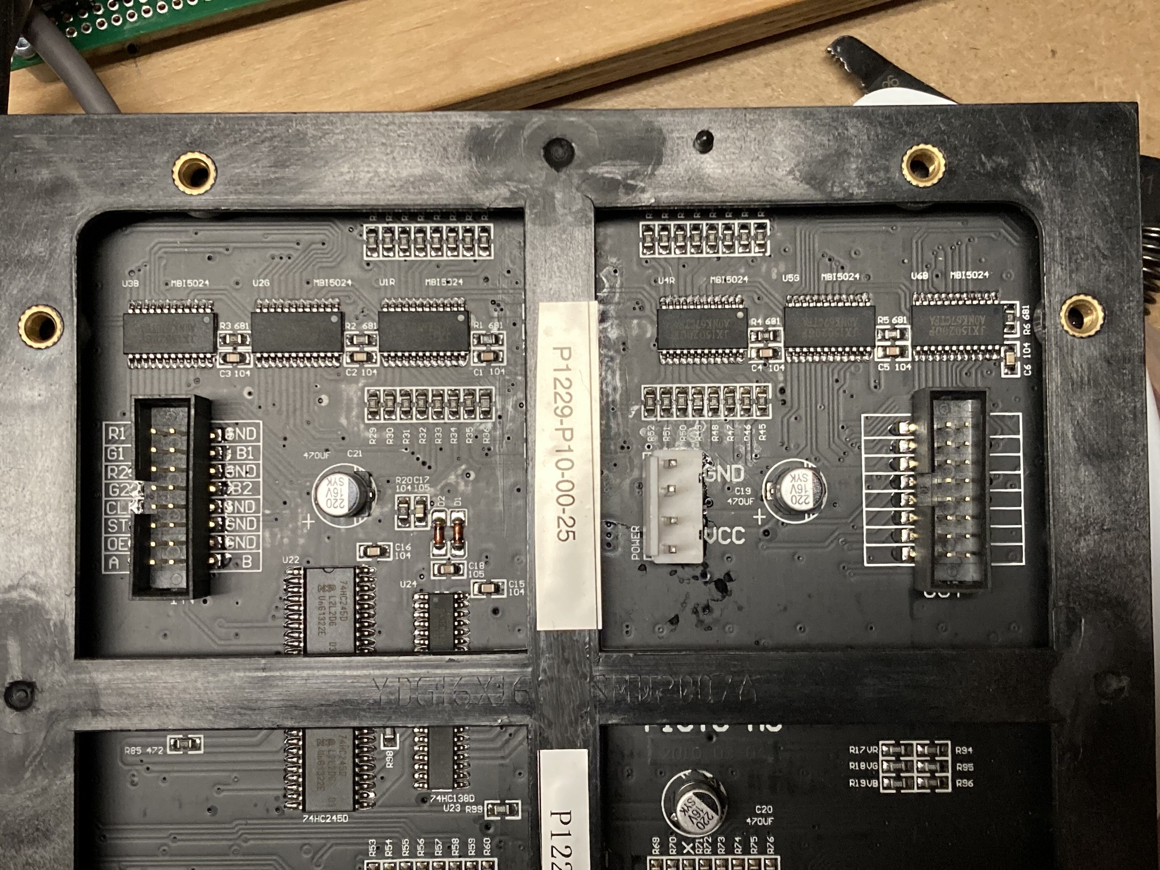
First you need to jumper 5 lines from the IN port over the the OUT port. To complicate things the OUT port is not labeled but the pins descriptions are identical to the IN port. Wire them as follows:
| P10 Panel IN/OUT Connections | |
|---|---|
| IN Pin | OUT Pin |
| R2 | R1 |
| G1 | R2 |
| G2 | G1 |
| B1 | G2 |
| B2 | B1 |

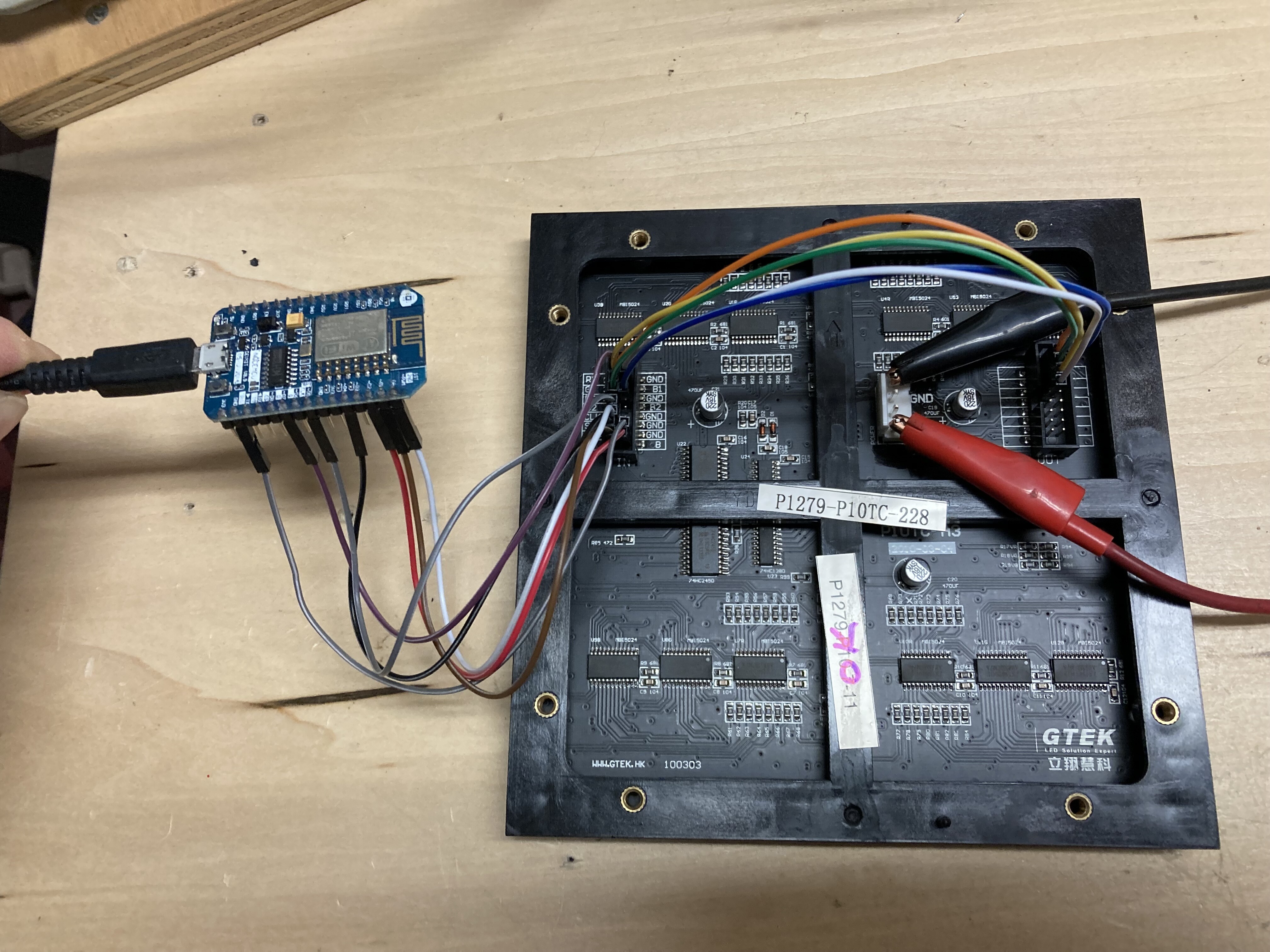
Next you need to connect your ESP8266 module using 7 jumpers. I used a NodeMCU in my example:
| ESP8266 Board Header Pinout | ||
|---|---|---|
| NodeMCU Pin | Description | P10 Pin |
| D0 | Latch | ST |
| D1 | A Address | A |
| D2 | B Address | B |
| D4 | Output Enable | OE |
| D5 | Clock | CLK |
| D7 | Data | R1 |
| GND | GND | GND |
You will also need to connect the ESP8266 to power. You can use you PC to power it while programming and then just use a cell phone charger.
You also need a 5V power supply for the panel itself. It connects to the power in (white port) where the picture shows the black and red alligator clips. The panels draw about 1 amp each at white full brightness so make sure your supply is suitable.
Now lets get the code running on your ESP8266. I used this library:
Which also requires FastLED:
http://fastled.io/
You can find a bit more info on using the library here:
Note that these are older 1/4 scan panels and don’t seem to work well when trying to make larger panel matrixes (at least I wasn’t able to but you may have better luck). However there are lots of fun things we can do with one or two panels)
You can install both libraries from within your Arduino IDE using the library manager.
Next you need to grab the code here:
VHS_Pixel_Panel_Tester_V1.2.zip (1.6 KB)
And open it up in your Arduino IDE. The code is reasonably commented but remember I am not a programmer. It is cobbled together with bits I found on the web. Upload it to your ESP8266 and you should get this:

It cycles through the primary (Red, Green, Blue) and secondary (Yellow, Cyan, Magenta) colors and then displays White. This is a good way to ensure all the LEDs in the panel are actually working. I have had some that show all 3 LEDs are working (se each if the R,G & B LEDs works fine) l) but then fails when doing the secondary colors(mixing the various LEDs). Make sure you can get this test app running on your panel before trying any of the other projects.
If you want a matching power connector there are some in a box (also in the furnace room)
I find the power connectors a bit too big so just solder the power to the pins for projects…
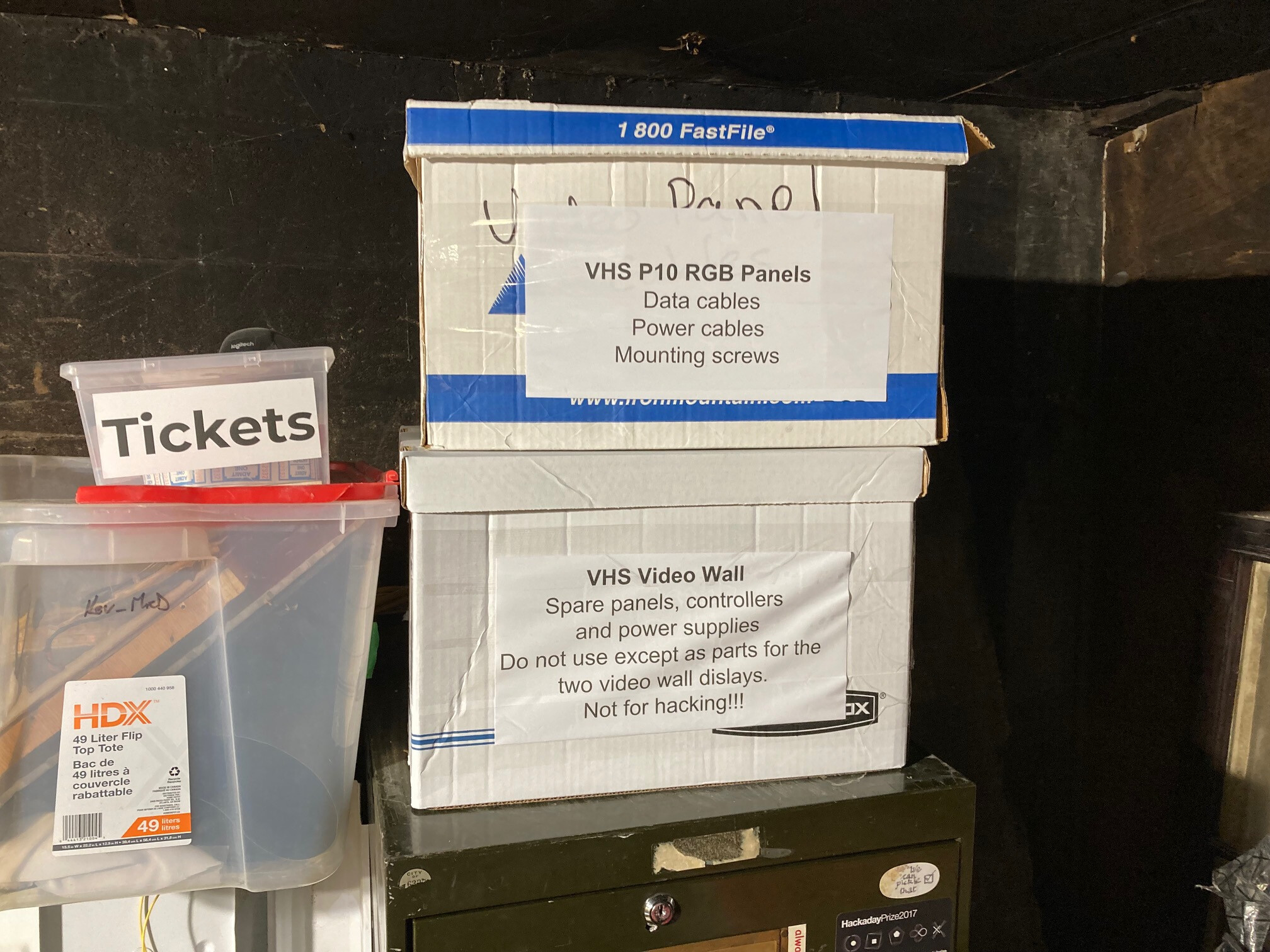
Please don’t touch the panels and parts in the box that is labelled for the Video Wall as these are spare parts we need to keep.