LED video wall, donated by a local non profit

Donation thread here: Led panel donation - #8 by dbynoe

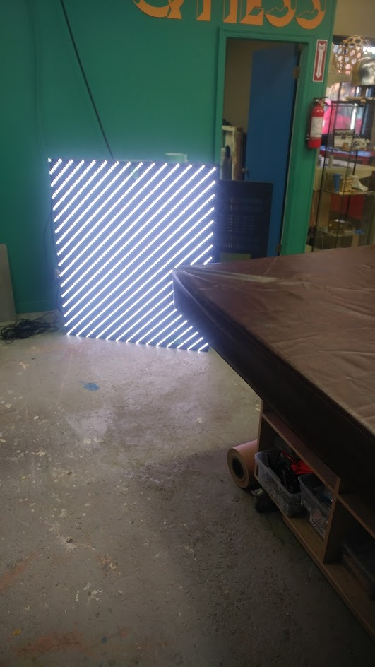
So we now have a video wall, well, most of it anyway. I am going to use this thread to document how to make these work.


First off, what we have is a

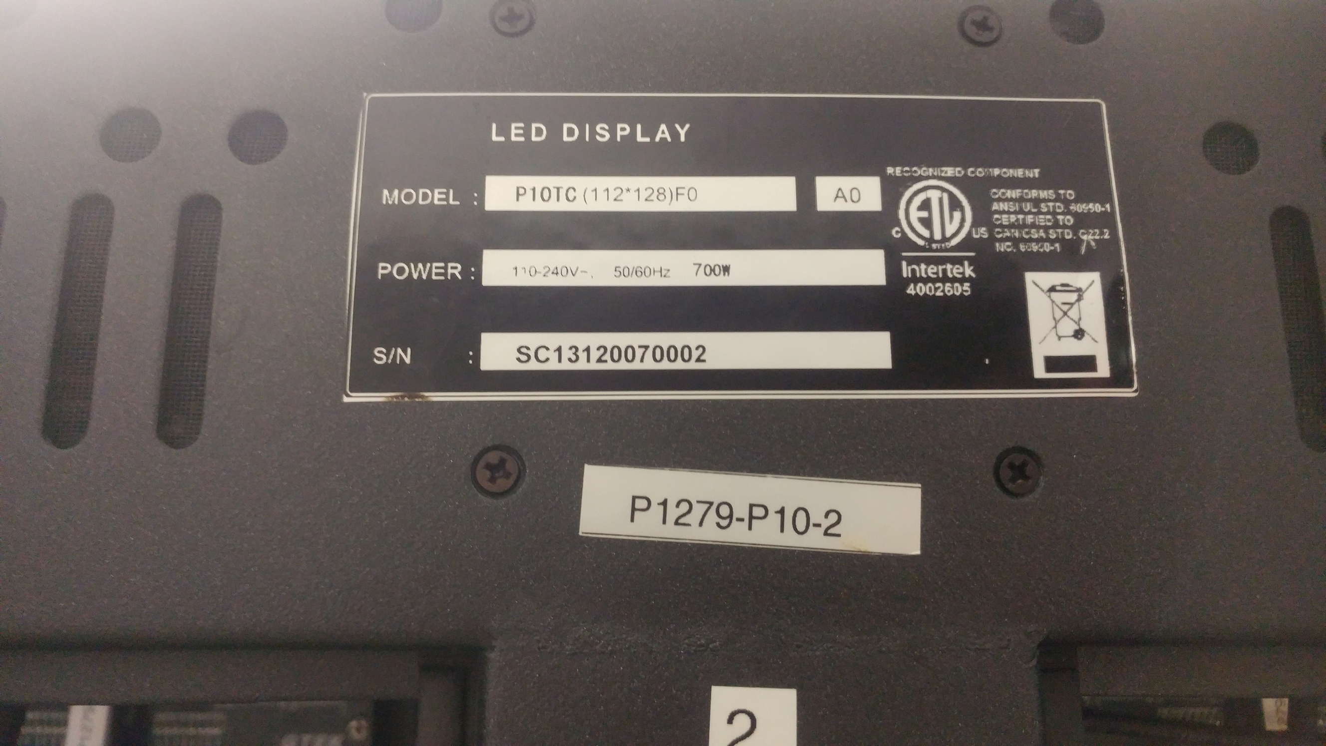
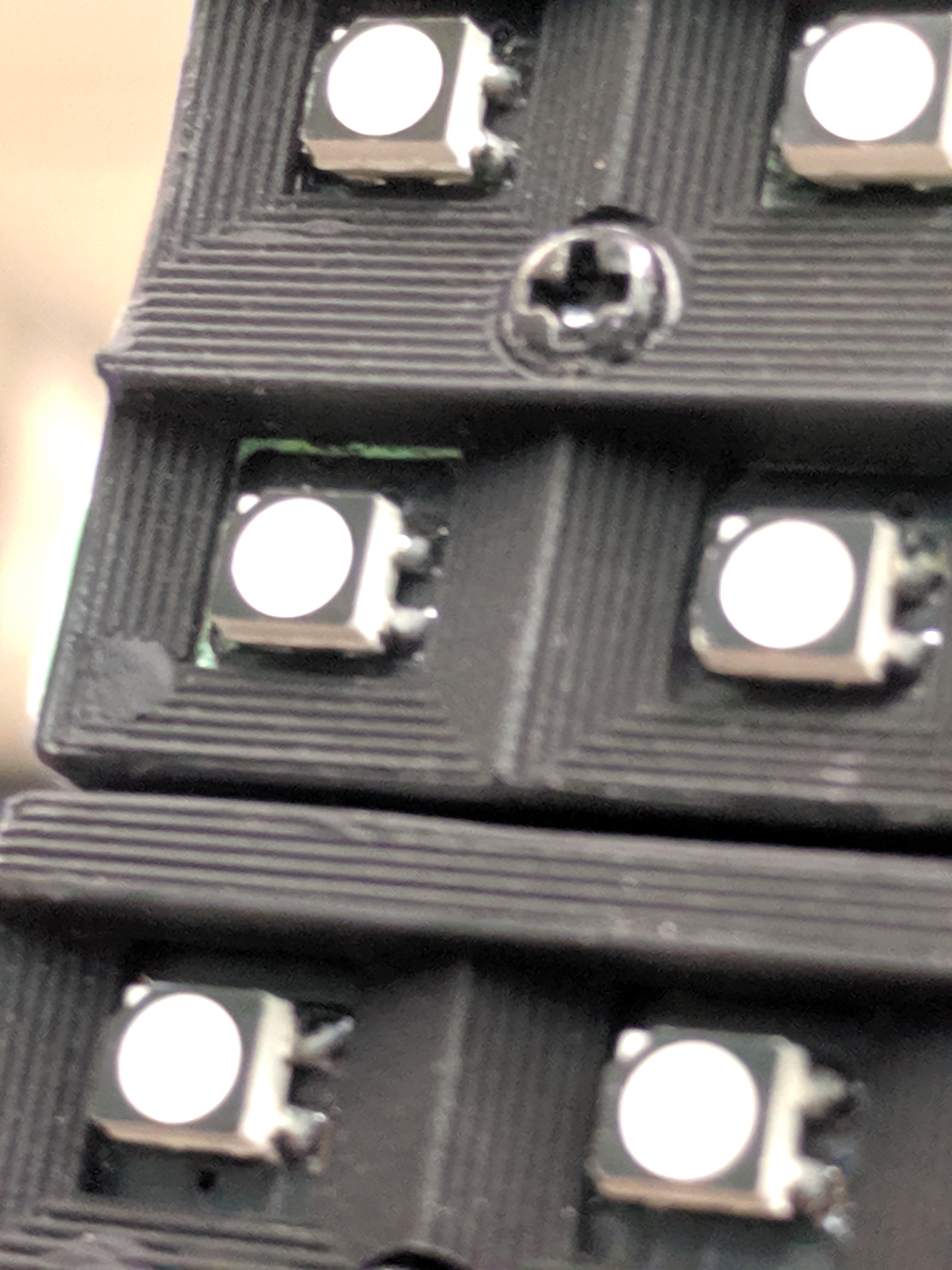
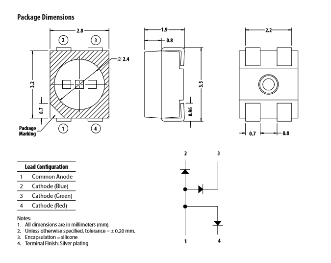
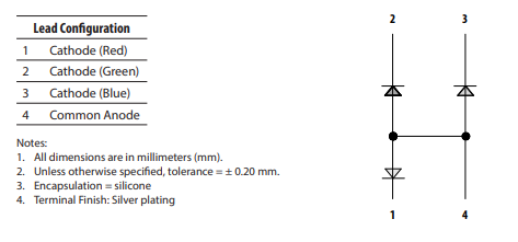
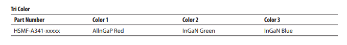
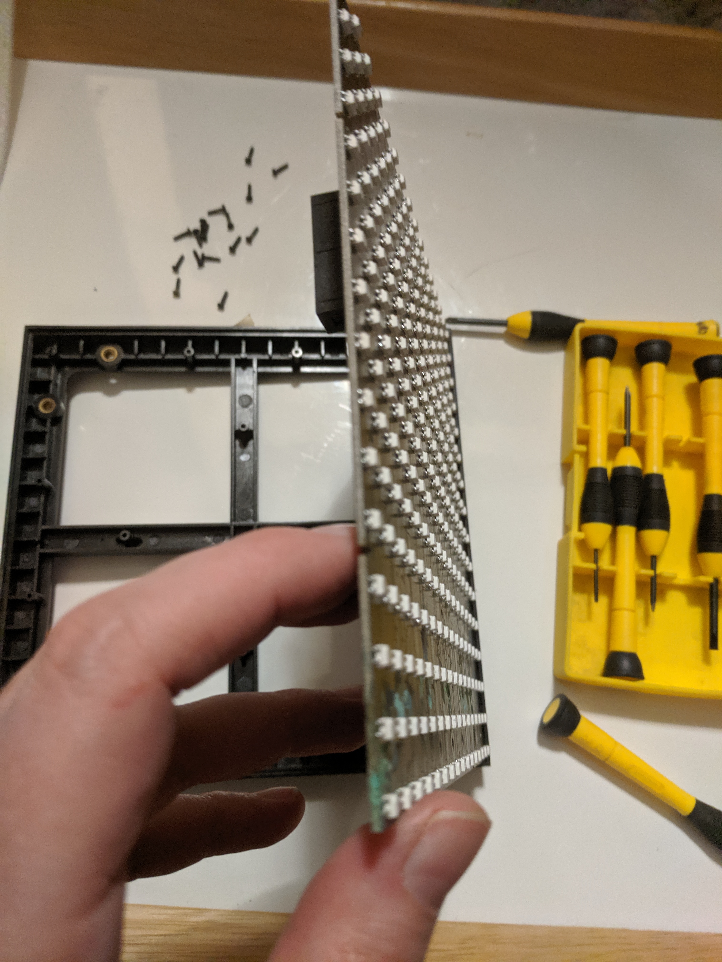
  • 8 4’x4’ ish x 112x128 pixel RGB matrix panels 10-12mm pitch.
  • some functional, some not apparently.
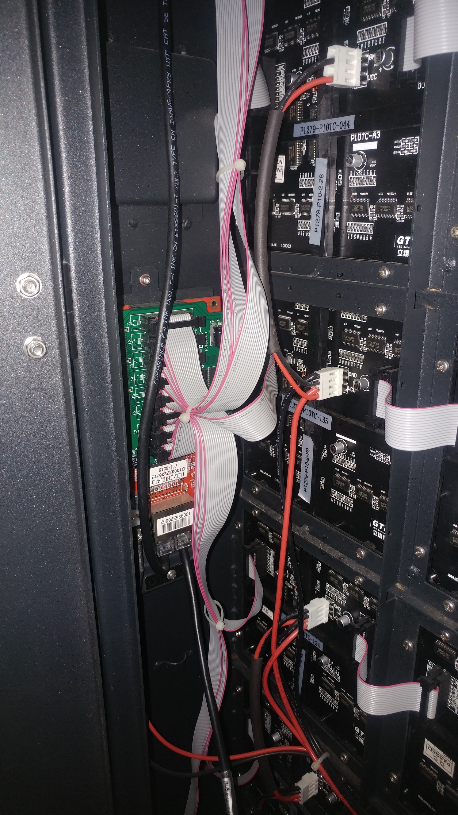
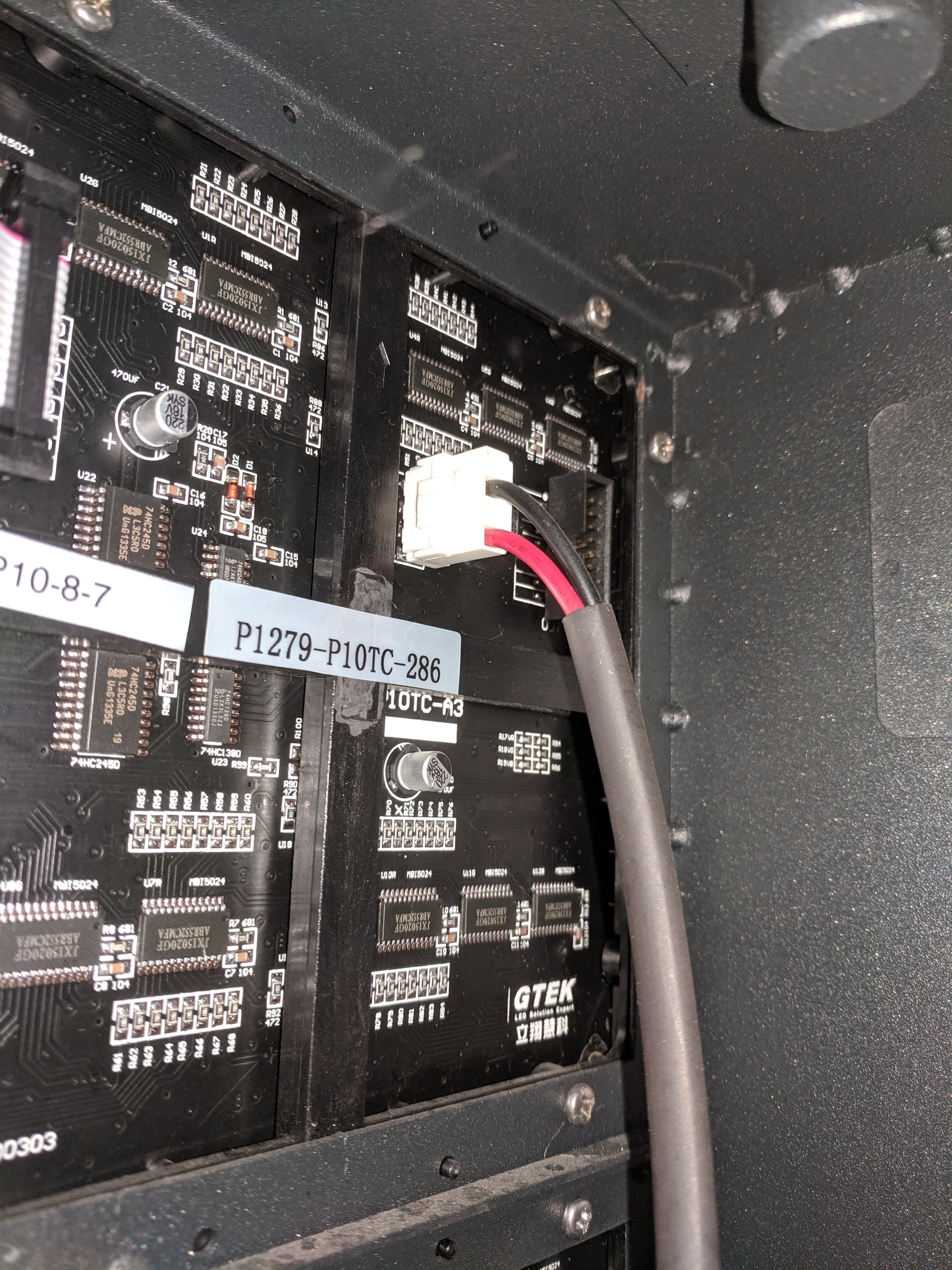
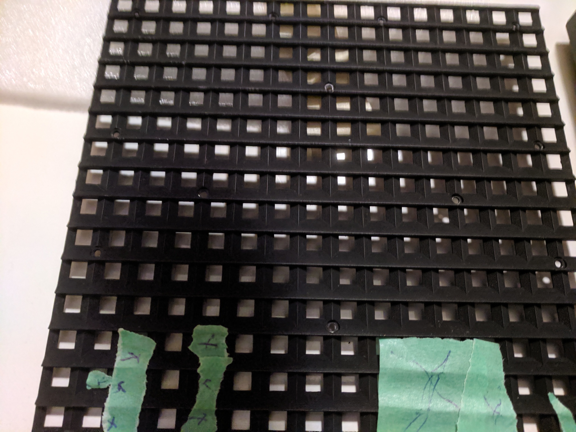
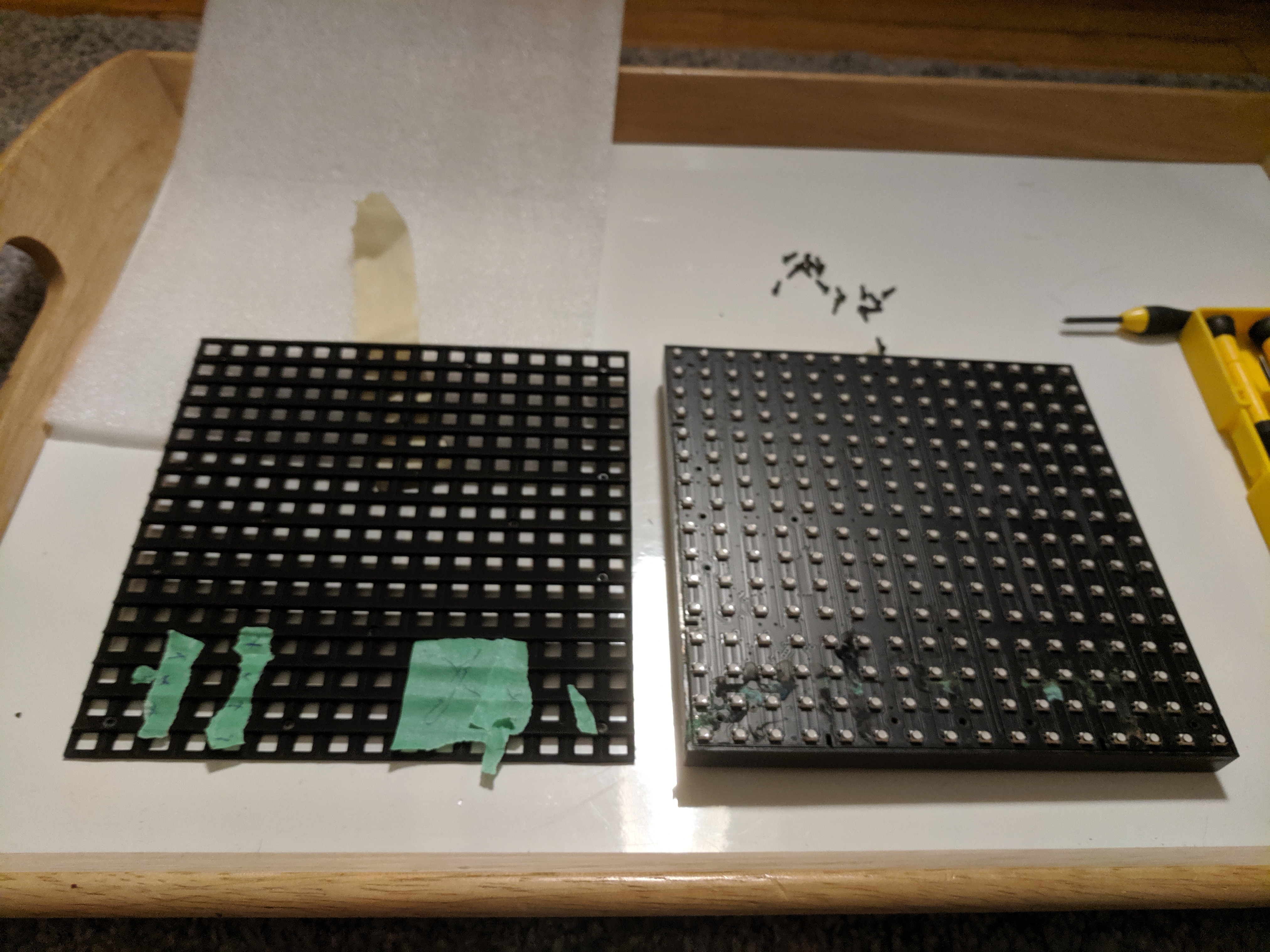
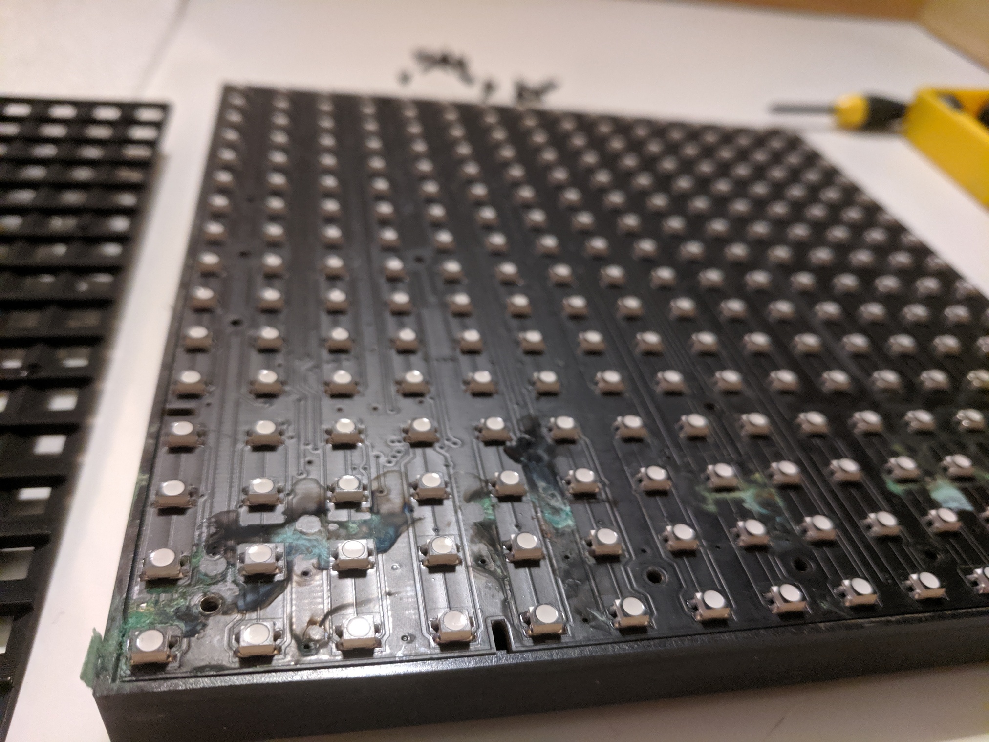
  • each panel is made up of 56 individual modules, its 7 modules wide and 8 high, so each module is 16x16.

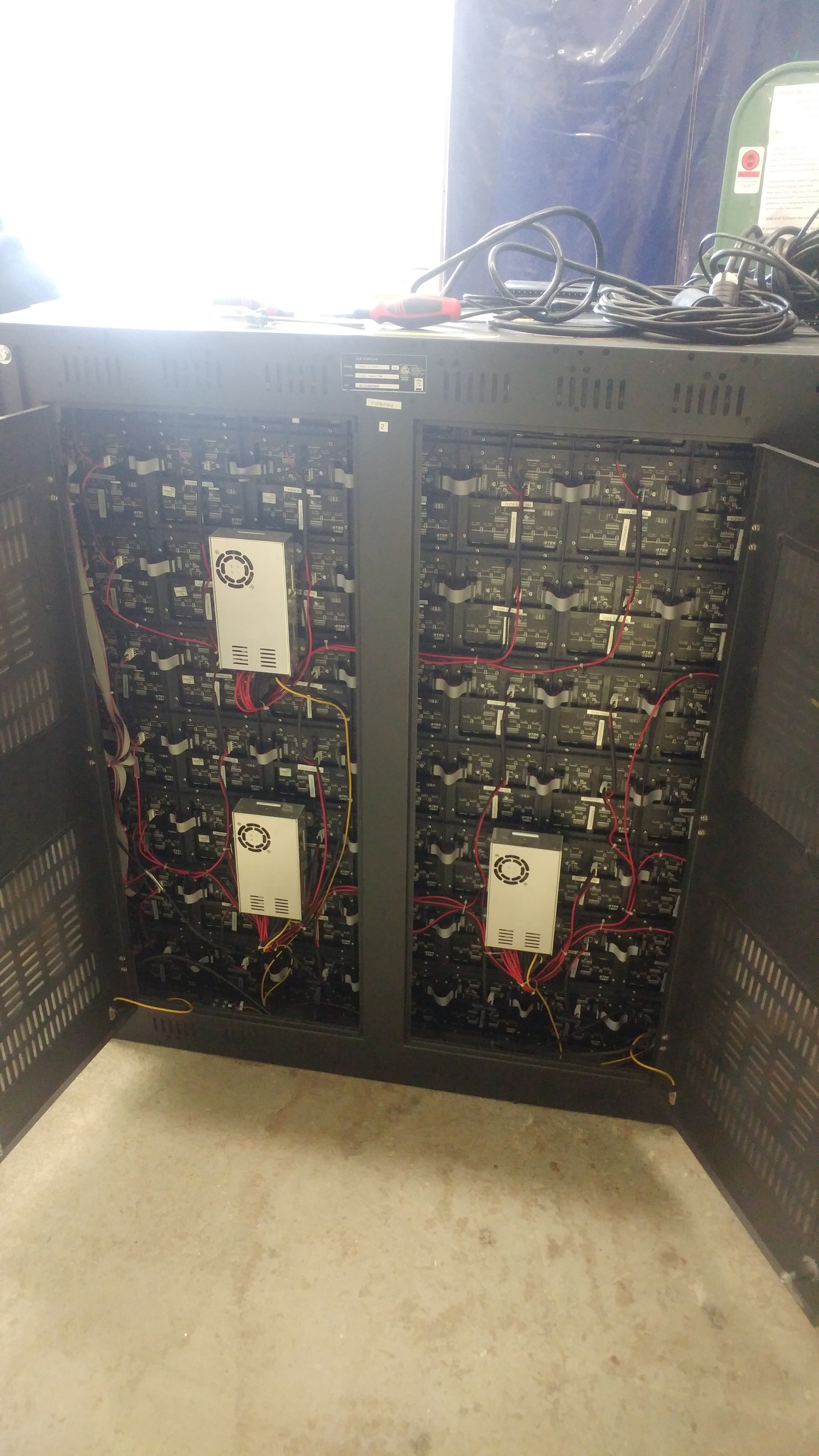
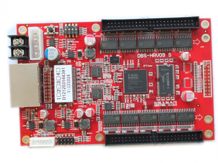
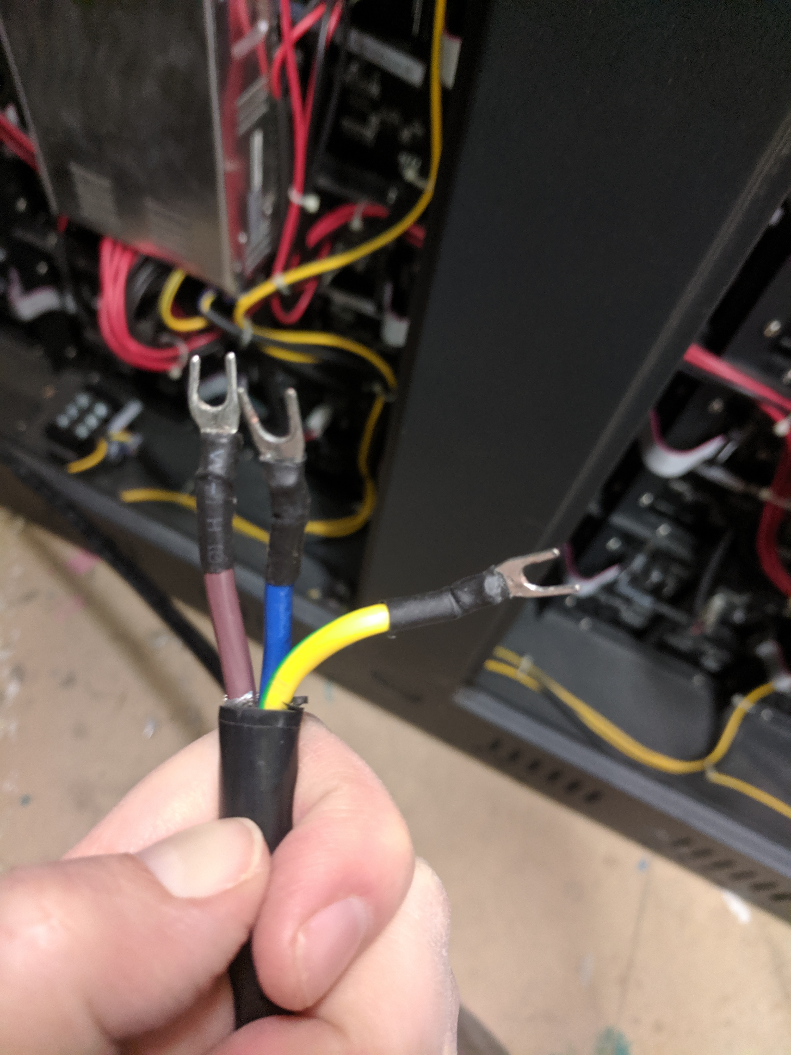
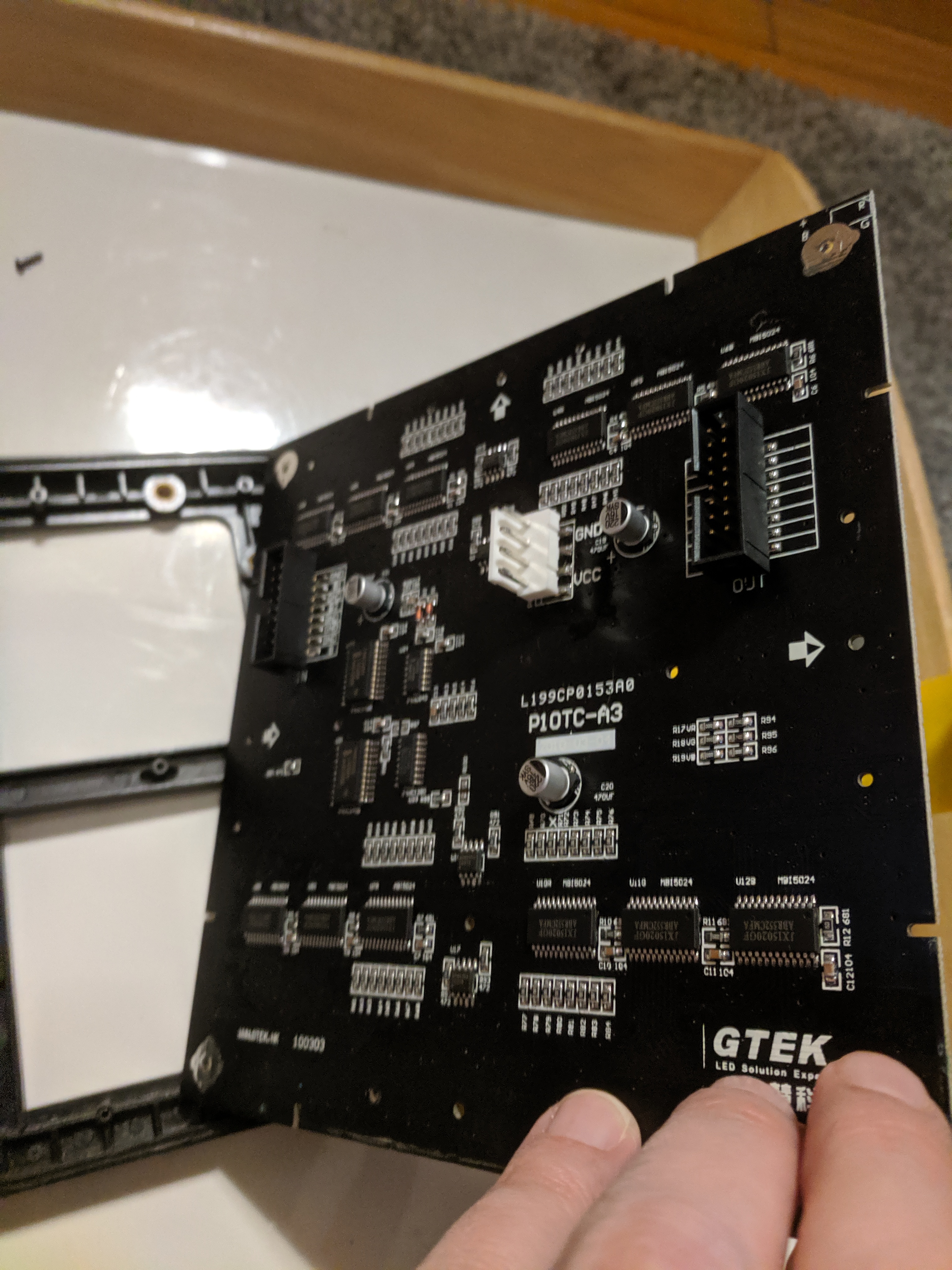
They are in a frame, with a series of power supplies, and a LED receiver cards.
I have sent an email to the to see if they happened to have the original sending cards.
*edit - nope they don’t have them, we can source them from china for around 100 bucks USD.

They should be something like this: Linsn LED Sending card,led receiver,led studio free led software-Linsnled.com I am not sure if this is the same company that makes the controller that is in ours. Of note, the driver card is in a pci form factor, but only uses pci for power, which means you can supply it with power externally without a power cable and drive it with a video signal.

Adafruit has a good tutorial on setting up and using these: Overview | DIY LED Video Wall | Adafruit Learning System

If we cant drive the entire panel, the individual panels are easy to drive with projects like Smart matrix which I have used in the past: SmartLED Shield V4

Someone did try to reverse engineer the communication protocol that was going out over the cat5 cable: Reverse-Engineering a chinese LED screen control.. thing. | INTERESTING! - Page 1

3 Likes

Looks like the same general idea as the Adafruit system:

https://www.adafruit.com/product/3649

Obviously not identical, but perhaps some code or usage strategies can be repurposed.

1 Like

I will upload photos in the morning, but the signs use a DRSTAR HRV11S receiver card which is a product you can currently buy, as well as the sender card

Even more interesting is this part has a test button, see page 9 in this pdf: http://www.adtronics.net/dwnld/?f=LED_Sign_Maintenance_Manual_v1_1517424877.pdf&p=downloadpdf
Basically hold test button for 5 seconds, and then press again to cycle through patterns.

Next time I am in the plan is to connect a regular plug to the thing (after checking that all the wiring looks safe) and give it a whirl.

*edit Oh and the moving forward plan is to source an appropriate sender card for a couple hundred bucks, that will connect to a windows pc over dvi and usb and we can use the panels as a monitor. Software is called dbstar XMplayer to control them, but the way I read it it needs a sender card, you’d think you could just connect it to Ethernet direct, but it looks like no, which seems odd give the horsepower of modern pcs…

1 Like

Saw them tonight and they are awesome. Thanks for making this happen/keeping things rolling. They look really well made - excited to see them in action.

Anyone have experience with ordering semi obscure parts out of China?

The part we need is one of these:
http://en.ledall.com/cpzxxx/productId=50.html

Which according to this aliexpress listing:

Is compatible with our HRV11S receiver card.

Yes I wish there was better documentation, if anyone can find a definite document saying this part works with this thing anywhere on the interwebs let me know. Right now I am going with:

  • its made by the same company
  • a few random store listings show them up as compatible
  • the company only makes 2 kinds of sender cards.

As for where to buy it, that is a question, all the suppliers are in china that I can find, and the prices vary a bit

$125 Ledinthebox.com: https://www.ledinthebox.com/dbs-hvt11in-full-color-led-sender-card.html

  • Seems legit?
  • Cheapest
  • not sure on shipping

$135 Ali express: Page Not Found - Aliexpress.com
also here
Turns out there are a ton of ali listings for this part, need to sort through them.

  • anyone ordered from ali express before?

$165 ledcontrolcard.com: http://www.ledcontrolcard.com/led-sending-card-c-15_19/dbstar-dbshvt11in-syncrhonous-led-sending-card-p-159.html

I am willing to throw $50 at this anyone else want in?

2 Likes

Not sure what is the best way to order, I only know aliexpress from those options, it’s usually worked out ok. I’ll pitch in $40

2 Likes

I have some spare PCBs for these fpga boards for driving panels like this.

2 Likes

That AliExpress product is C$179.11, plus C$15.43 for AliExpress Standard Shipping which is pretty good/fast and very unlikely to trigger duties upon delivery. That’s probably the best option.

Alternatively there are some on TaoBao for ¥750.00 (C$138). I have a pending reshipping order with Dangerous Prototypes I could throw this on. However by the time it’s reshipped by DHL, and some taxes and duty added on, it’ll probably be basically the same price.

2 Likes

I’m also in for $50.

2 Likes

So got the panels tested and good news, all the receivers are working as well as most of the modules, and they are bright!


There are few dead pixels but way less than I thought based on the description.

Each sign is made up of 56 individual modules, so out of the 448 modules total:

  • 419 are perfect
  • 10 have issues with a single pixel missing at least one colour.
  • 19 more have issues with 4 or more pixels

Jarret figures we can source and solder on new leds if needed to repair modules.
Upshot is, the pixels don’t show as black but just as pink or blue or red when displaying white. I should have taken photos but eh… busy. Its the kinda thing I could live with just leaving as is for most of them, or take Metal_Janets idea of turning them into a cyberpunk glitch panel.

Current consumption is as follows per panel for solid colours.

  • 5 amps for red
  • 2.2 for green
  • 1.5 for blue
  • 8 amps for full white
  • 4.2 amps for a test pattern with a fade across the panel (roughly equivalent to a half white)
  • 1.4 amps for that test pattern show in the image up top (diagonal stripes)

Opening instructions, provided you know what you are doing and know not to lick/touch/fondle live 120 or a bunch of really angry 5v. To open the back of the signs you’ll need a 9 mm socket on the latches (the things with the weird triangle in the middle), inside the sign is a cam to a latch bar, rotate it 90 degrees.

To supply power, connect a power cord to this terminal block located on the left hand side bottom of the panel.


Connections in order from door to screen are: ground, neutral, hot. Or in colours, yellow/green, then blue, then brown.

The power cord for the signs is located in the tote marked dbynoe (top shelf, the one on the end facing the work table). I hid it because it has exposed conductors on the panel side and plugging it into the wall without having connected it to something, could be dangerous, you’ve been warned. Feel free to use it if you know what you are doing, just put it back when you are done so some wandering child doesn’t get a 120v surprise.

There were only two power cords for all 8 modules, so we have to share until we come up with the rest of the plan.

Once powered (very important) test mode is activated by pressing the test button on the receiver card.

Cant see it in the photo, but if you look at this card in person, just below the green daughter card on the red base card on the closest to the door edge is a microswitch. Press and hold for 5 seconds and the sign will light and go red. Press again to cycle through the modes.

Here is a view of just the card


See the button in the top left beside the molex? that’s the one, oh yeah don’t touch the molex with wet fingers. or anything else inside while you are at it and its live, there are 165 amps of 5v and a bunch of live 120v so you know, don’t screw it up.

5 Likes

Thanks for the pledges, I make the total out at $140 so far. Looks like its going to be around $200 Canadian to pick up that sender card, plus whatever border insanity. So we are $90 short.

Probably going to order it today and continue fundraising, worst case I’ll donate the rest.

I’ll go for the standard shipping, thanks Luke for the tips.

Reasons I am going to order this card vs rolling our own solution:

  • Works with the parts we have, one sender is capable of driving all 8 of our panels, it should be basically plug, setup, and party.
  • Will make the panels act like an external monitor - it selects a certain portion of the dvi video stream and mirrors that up on the panels, just drag whatever to that spot of the display and it shows up on the sign. Yes that explains the windows error messages in times square.
  • Has software to reconfigure the panel layout - for windows only.
  • Wont require programming skills to be able to use the sign, if you wanted to show everyone say He-Man grooving out to four non blondes, just find the video, and drag it to the right portion of the screen.
  • doesn’t preclude programming as you can always write something to display on the screen with Processing, or whatever interactive visualization software you want, or just a browser window and a cat video playlist.
  • doesn’t preclude building up a linux machine to drive it (anything with a DVI will work), only the configuration program is windows only.
  • its super easy for us to reconfigure it later with the software. Want to build a giant infinity mirror pentagon? or a 30 foot long ecg? or fill all the front windows of our building? or drag 2 signs out for an event? Each panel has a couple cat5’s and a power cord. Rejigger the sender set up, connect it to a dvi and you are golden.

Other things I looked into like teenys with smartmatrix code will only drive 64x64 pixels (each panel is 128x112 and we have 8 of them). FPGA’s are very cool, but complicated for your average hacker (though I really think people should play with it, its like 8 connectors inside and you can connect whatever to the modules).

So yeah, it will take a month or so to get here, start thinking up what insanity you want to build with this thing.

3 Likes

I’ll go in for $40…

4 Likes

In for $40.

2 Likes

Did some work on this today.

I made the mistake of plugging it into a power bar and blew a breaker (which I fixed). I ended up plugging it into the outlet next to the metal chemical locker in the painting room. I used the long extension cord from the server room.

Hooked it up, following Dave’s excellent instructions above.Dead pixels easy to see on full white. I wore sunglasses to cut the brightness. Thanks for marking the problem spots Dave. Took one small panel out. They are pretty easy to remove. I took it home to resolder the busted pixels. See pics below. Will report back. Note: screws to loosen the panel from the chassis are on the inside.

FYI: as soon as you take the last screw out the whole panel will fall out - don’t ask how I know. :smiley:

4 Likes

Here’s the pixel pinout if anyone is interested:

Here is the full datasheet for the pixels. V02-4186EN_DS_ASMB-MTB0_2014-09-10-909697.pdf (420.5 KB)

Thanks to Jarrett for digging this up.

Update! This may not be the right pinout - just doing a few tests to figure it out. Jarrett showed me how to do a diode test with a multimeter.

4 Likes

Janet just did some poking (literally, with a multimeter), and results didn’t immediately line up with expectations.

Option number two:

ASMB-MTB1-0A3A2

image

Option number 3:

HSMx-A3xx-xxxxx Tri-Color


image

2 Likes

Physical Teardown:

  • front grill is plastic, 15 small screws to remove
  • board is solid and mostly in good shape
  • some copper corosion around borked leds
  • one small hole in coating exposing copper on led-side of board (looks like water damage)
  • removed with isopropanol

Testing:

  • my diode test wasn’t working so did a few quick tests with arduino but didn’t run these too long as the thing wants a lots of amps/it gets warm. Top of the board is under my left hand.
  • the pinout I got is below (which makes it #3 from the options @jarrett posted)


image
image

After cleaning off the corrosion and testing the leds I’d marked they seem to work as expected. Hard to know if LEDS are still stuck on a particular colour in blocks. Need enough amps to power the whole board.

Next: Will try this at the space with a power supply before getting down to resoldering individual pixels.

Edit: if it’s just corrosion - wooo! These things were originally outdoors weren’t they?

4 Likes

missed the update earlier, but I’m in for $40.

2 Likes

Thanks everyone for the pledges! PM’s have been sent with details of how to get the money to me.
Tracking shows the sender somewhere between China and Canada… Soon… Soon…

Thanks Janet for looking into the dead pixel problem if its mostly just fixable corrosion that is so awesome.

For those planning out where to put this thing. Each panel is just a smidge over 44" wide, and 55 3/8" high.

The back wall of the classroom upstairs is 131" wide and 96" tall. I am not sure if we can rotate the panels in software but that would mean we could stick a 2x2 grid mounted sideways upstairs. Just a thought.

1 Like

Still on it - I caught a cold so hope to be back to it on Monday. Looking forward to playing all my cat videos on there.

1 Like