I have purchased a set of PCB milling bits.
In order to not murder myself and other members of the space, only FR-1 PCB blanks will be used.
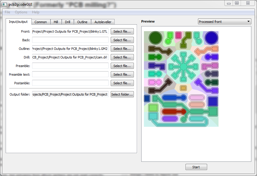
PCB2GCODE has GUI for windows and linux.
does a pretty good job of generating Gcode. Tested with gerber files generated with eagle and altium. gerber file must be RS-247x, and drill file must be excellon format.
Had the most success with Altium. but polygons from altium gerbers are not read correctly
I don’t know how to generate board shape file in Eagle
@xquared I really, really wish I could share these adventures in person so I really appreciate your sharing here. I’ve bought a CNC 3020 kit for home that I hope to use for PCBs, the toolchain info here is fabulous.
BTW is that a real circuit or a torture test, looks very pretty.
Consider buying a supply of 1206 and 0805 0R resistors. These will function nicely as jumpers since they have plenty of room under them.
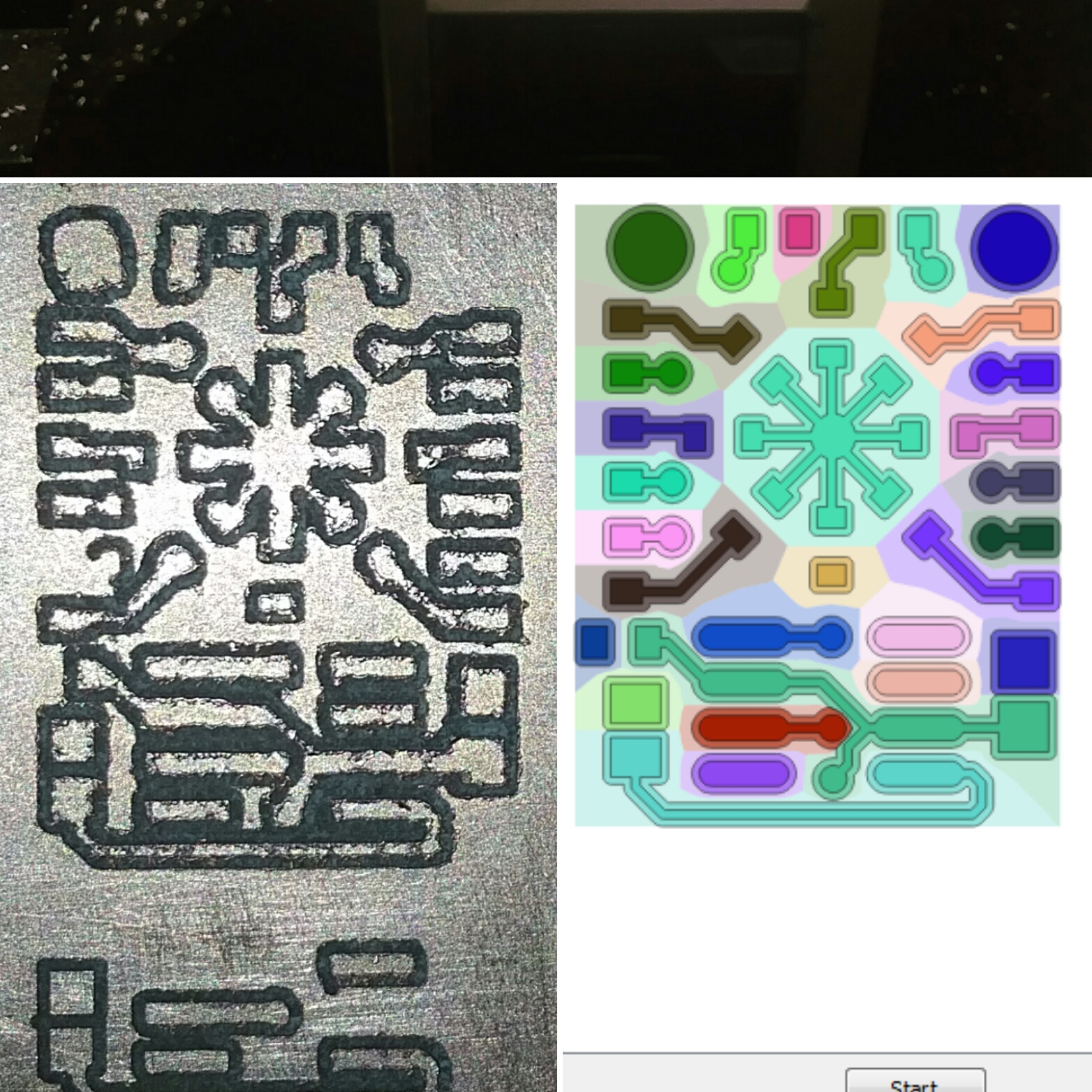
the circuit is the front of a blinky 555 pendant i made.
i just happend to have the gerber file handy. but i don’t think the milling process worked well for 0603 smd footprints. 0805 and up are definitely do able.
I think the z-axis is definitely missing steps. The traces all of sudden disappeared.
The missing traces are spread out over the pcb, so it’s unlikely that the PCB was not flat. If the tips were worn the effects should be more gradual.
So I think it makes sense that the z-axis was missing count in between all the up down movements.
It might be backlash in Z - I can see there’s quite some in X/Y also from the not-so-circular circle in the upper-left. There should be a setting in LinuxCNC for calibrating out the backlash for each axis.
To measure backlash for an axis:
Disable/0 backlash compensation if it’s already configured/enabled
Set up a dial indicator attached to the spindle and oriented in the direction of the axis
Jog the axis (in one direction only, don’t back it off unless you back it off quite a distance and go again) so the indicator is pressed (gently!) against something like the vice
Zero the indicator
Now single-step that axis in the opposite direction to the previous jog, to back the indicator off from the vice
Count the number of steps it took until deflection was seen on the dial indicator and from that calculate the total travel the machine was attempting to do - that’s the backlash for the axis (not the deflection on the indicator itself!)
How fast are you feeding? The round traces don’t look very close to shape. Is there backlash going on here? Or perhaps the machine can’t keep up with the programmed feedrate.
Thanks, for the suggestions, @rsim and @Big_Mak
I will look into the backlash issue first thing when I get back. Other than software compensation, anyway to tighten up the tolerance mechanically?
Next thing on my list is going to be wiring up a charge pumped and z-axis probe.
Yes, but good reasons not to. Backlash varies along the leads crew according to wear patterns. I think the rule of thumb was that more than 005" is when you need to tighten up. Sherline user manual shows how to undo the antibacklash nut, it’s a little tricky as I recall. I think I still have my manual somewhere . You’re looking for two little. Brass gears locked down with a button head hex screw.
@Gear105 helped me look at the sherline.
it’s got step accuracy issues as well as backlash issues. he suggested new controller and motor to retrofit it.
so i am waiting for the current taig motor to retire and grab them
Tonight, @colorcoded and i worked on sherline a little. @colorcoded managed to build both pcb2gcode and pcb2gcodeGUI on the linuxcnc machine. we are now able to generate g-code on the machine from gerber files. Thanks, @colorcoded !
we ran into some issue with generation of the config files. from what i can tell, the .ini and the .hal files were edited outside of the stepconf wizard, thus changes are not reflected in the .stepconf file.
Getting pcb2gcode to compile on the linuxcnc machine was a little challenging, so I have distilled the procedure down to a bash script in case we need to do it again in the future:
git clone https://gist.github.com/martinhansdk/db5fd127f85bfd5e2907a5f6c733f2db build_pcb2gcode
cd build_pcb2gcode
bash build_pcb2gcode.sh
Since last night, the configuration files for linuxcnc are under version control with git. They are located in ~vhs/linuxcnc.
So before you attempt to change any configuration it is a good idea to make sure that the current version of it has been committed. After making any changes that work it would be great to commit them with a short message that explained what was changed. You can use git gui for all of this:
So some of the links for the motor controller listed on the reprap wiki page is now dead.
i found a manual else where and am attaching to this thread for reference. 20111013_77767.pdf (1010.9 KB)
As far as i can tell, pin 15 on the parallel port has no connection on the board, so i soldered a wire to the pin on the PCB side. this will eventually be connected to the PCB blanks.