
This a nice kinda artsy project that runs through a bunch of effects sequences on a VHS RGB Panel…
It is based on the Aura demo (fram the FastLED library) that cycles through a bunch of effects
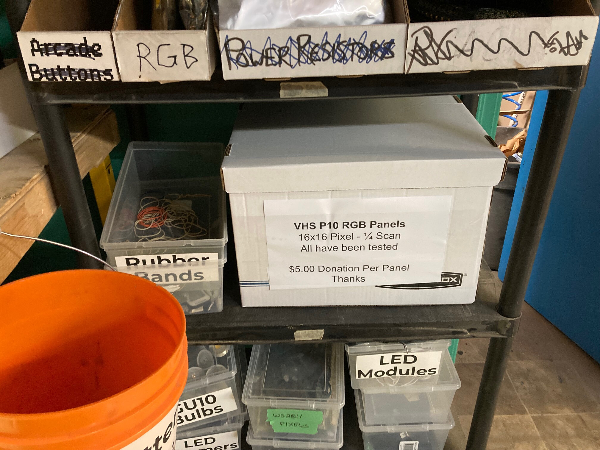
We have a fair pile of tested (marked OK on back) and working 16x16 RGB LED panels available for projects… These are in a box in the LED rack (next to Ecycling shelf). The cost for each panel is $5.00
You can either drop cash off in the donation drop box or eTransfer to the Space…
In order to make a VHS Pixel Panel you will need the following:
- VHS RGB Panel
- ESP8266 Module (NodeMCU, WeMOS, etc)
- Female to Female Dupont Jumpers
- Misc wire to connect power supply
- 5V 1A power supply
You also have to have the ESP8266 core support added to your Arduino IDE:
#################################################################################
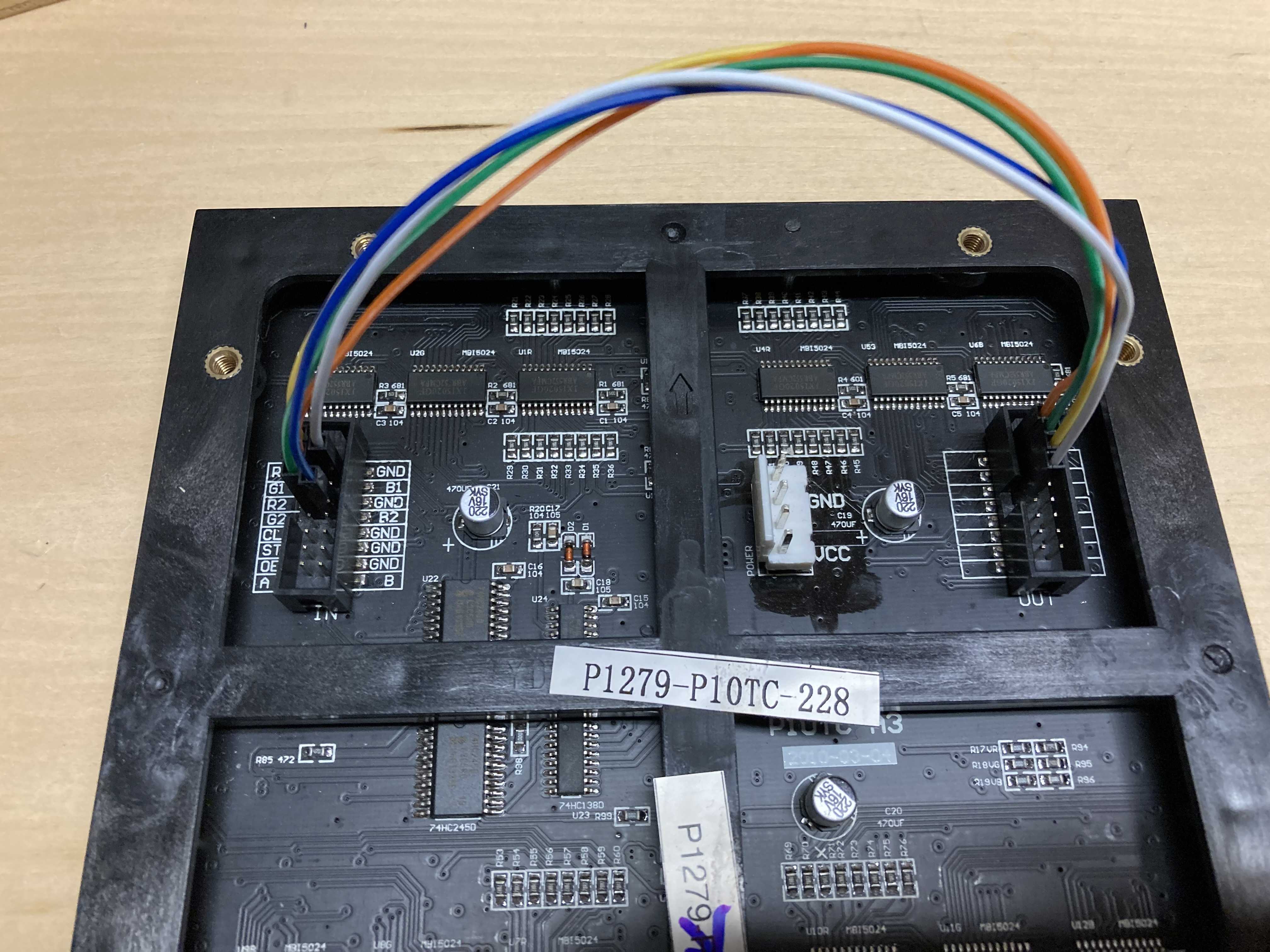
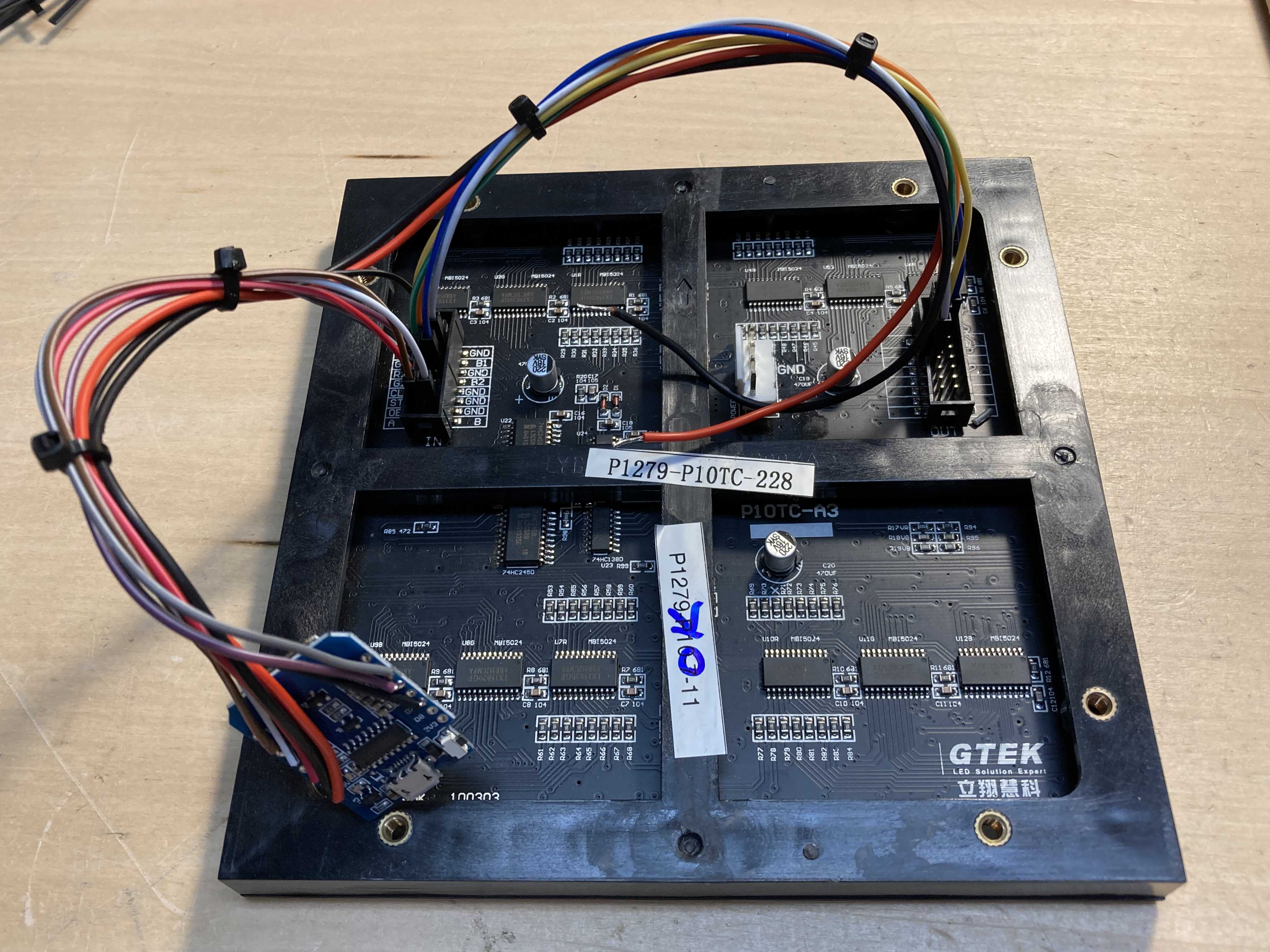
First you need to jumper 5 lines from the IN port over the the OUT port. To complicate things the OUT port is not labeled but the pins descriptions are identical to the IN port. Wire them as follows:
| P10 Panel IN/OUT Connections | |
|---|---|
| IN Pin | OUT Pin |
| R2 | R1 |
| G1 | R2 |
| G2 | G1 |
| B1 | G2 |
| B2 | B1 |
#################################################################################
Next you need to connect the ESP8266 module . As I wanted everything to be compact I used a WeMOS module without the header pins. I cut off one connector on the DuPont jumper wires and soldered each directly to the ESP8266 module as noted below. I also connected a pair of wires to the GND and +5 terminals.
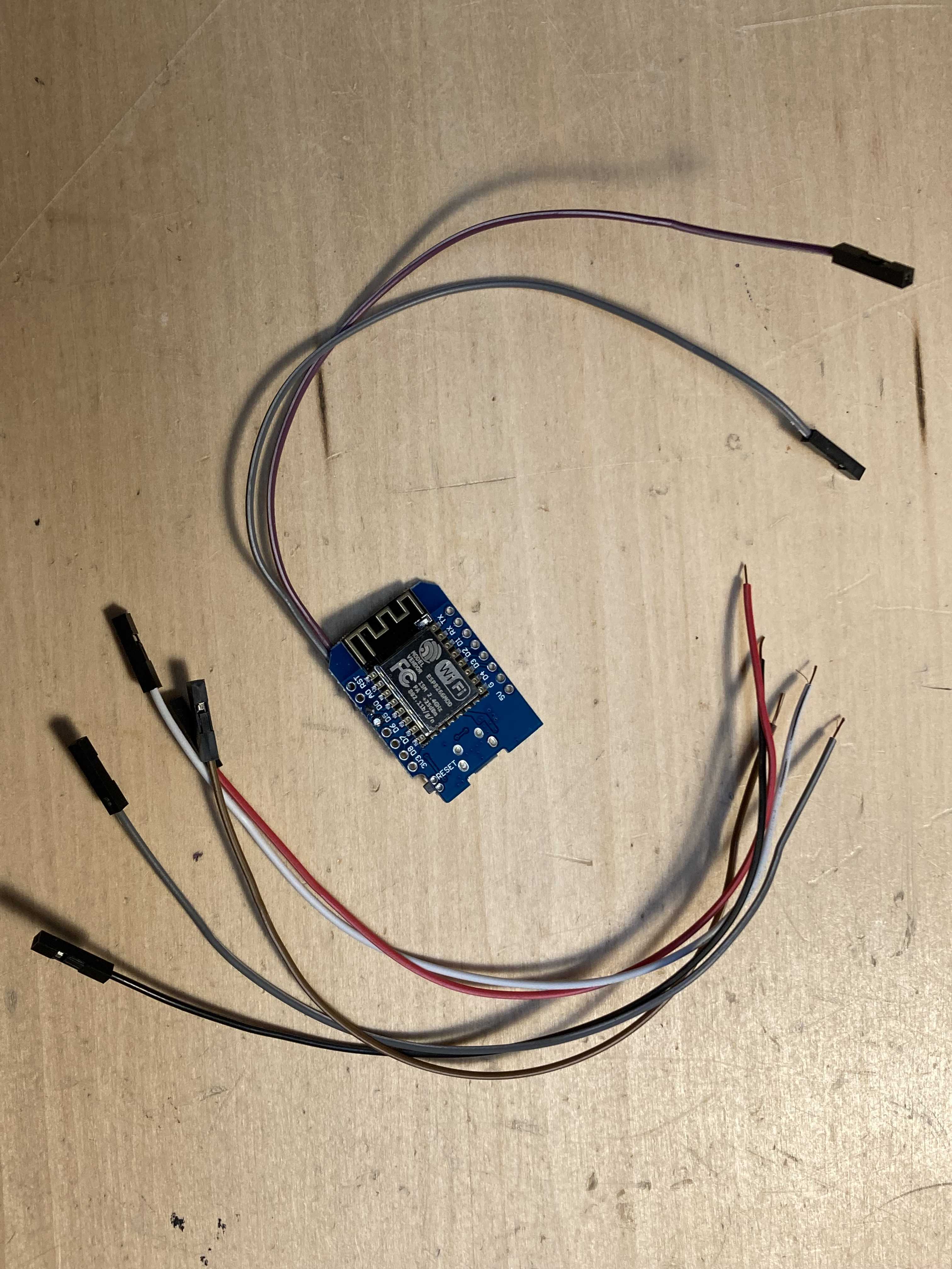
| ESP8266 Board Header Pinout | ||
|---|---|---|
| NodeMCU Pin | Description | P10 Pin |
| D0 | Latch | ST |
| D1 | A Address | A |
| D2 | B Address | B |
| D4 | Output Enable | OE |
| D5 | Clock | CLK |
| D7 | Data | R1 |
#################################################################################
Next connect the signal wires from the ESP8266 to the IN connector on the panel
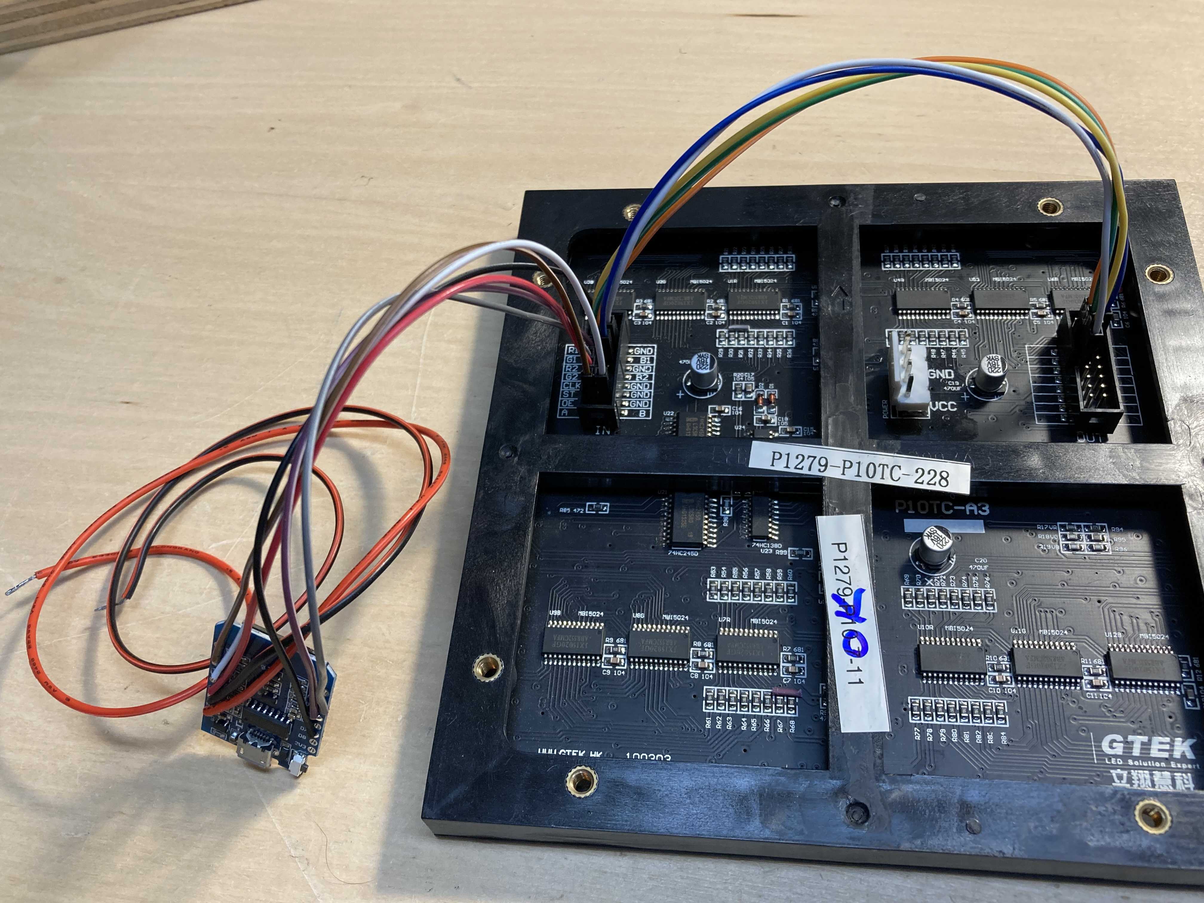
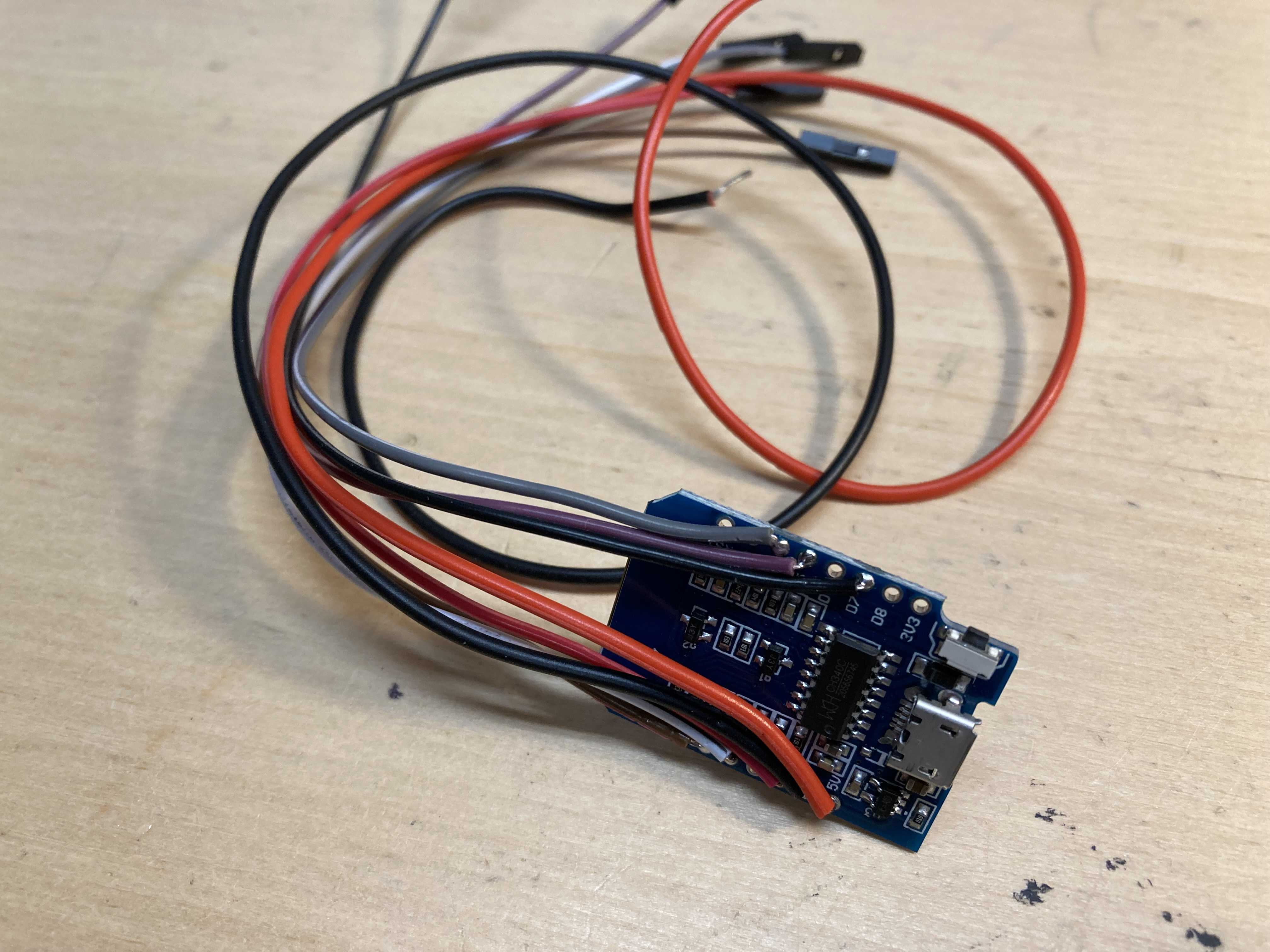
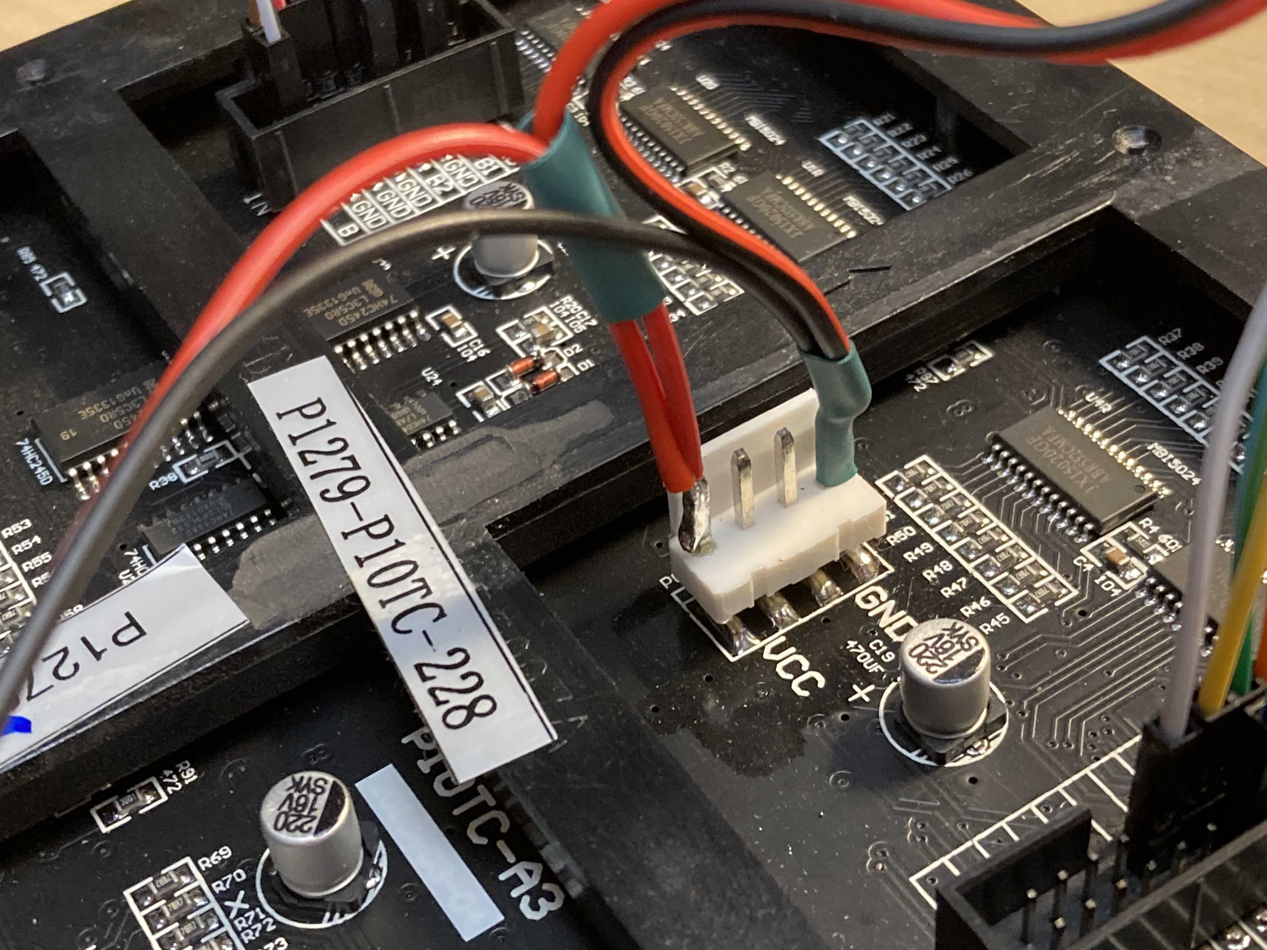
Then run the power wires from the ESP8266 to the power terminals of the RGB panel.
Next I soldered the ESP8266 power wires and the power supply wires directly to the power pins on the module. I didn’t use one of the power connector wires as it was too bulky for what I wanted.
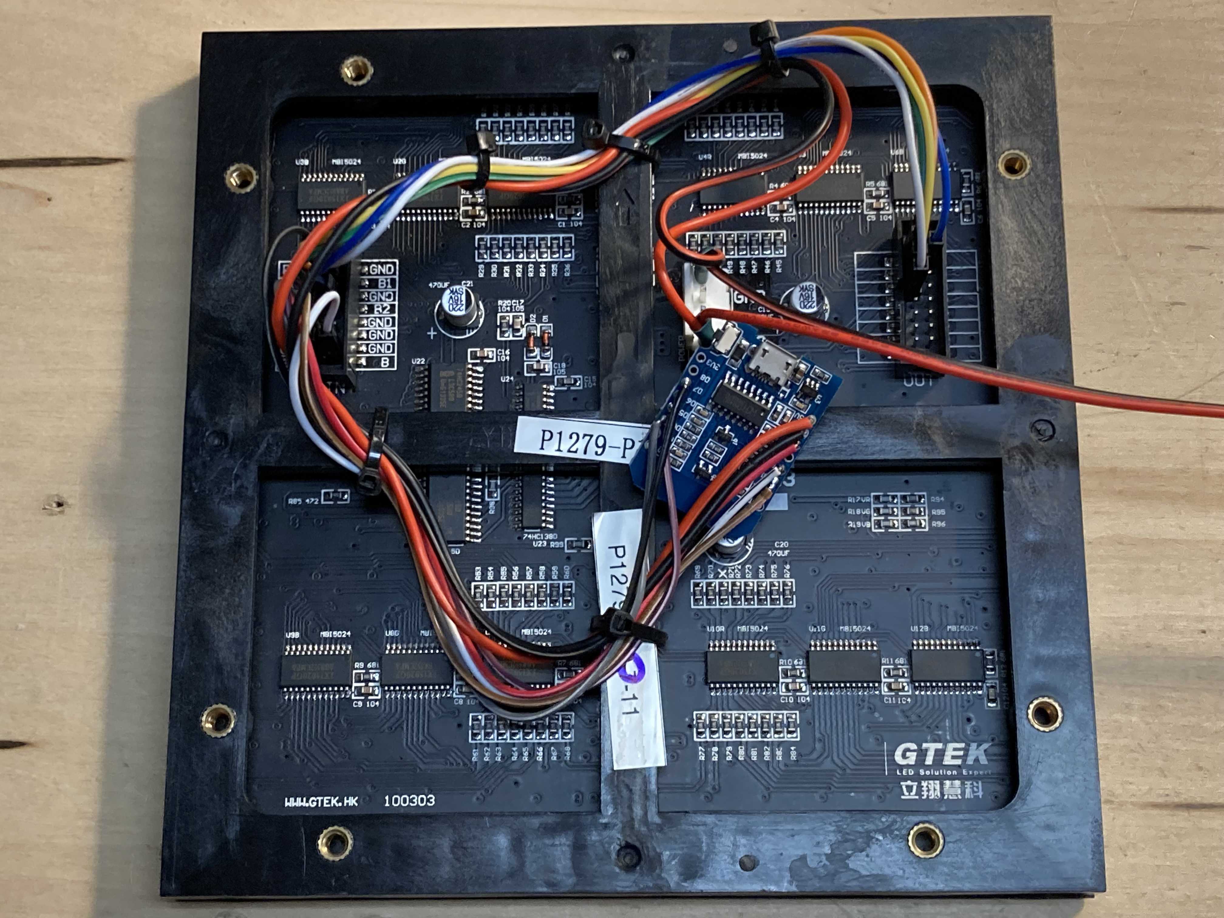
I then secured all the wires with some tie wraps. I’ll cover the ESP8266 module with heat shrink or Kaptan tape once I have it programmed.
#################################################################################
Now lets get the code running on your ESP8266. I used this library:
Which also requires FastLED:
http://fastled.io/
You can install both libraries from within your Arduino IDE using the library manager.
Next you need to grab the code here:
VHS_Pixel_Panel_V1.2.zip (64.8 KB)
Using the Arduino IDE load this into your ESP8266 module. Make sure you have it connected to a 5V power source that can supply 1 Amp. And you should get the various patterns as displayed in the video.
I mounted mine on a 10" x 10" square of plywood painted flat black… This allowed me to hang it on the wall.
