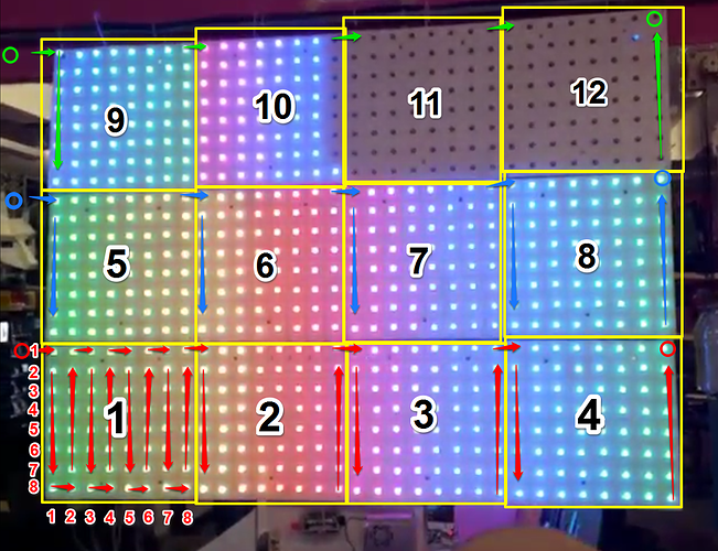
There is numerous posts about the LED wall.
- [Space Project] LED Wall
- Please Help! The LED wall is not working
- VHS LED wall
- Vhs led wall is alive!
- Where will the LED wall clock / graffiti be placed?
And two projects on github that I could find about the LED wall.
None of these posts or repositories have any documentation on how its set up. VHS seems to be allergic to documentation sometimes. I tried connecting power to the current set up. The Raspberry pi and the Teency both powered up but the LEDs didn’t blink. ![]()
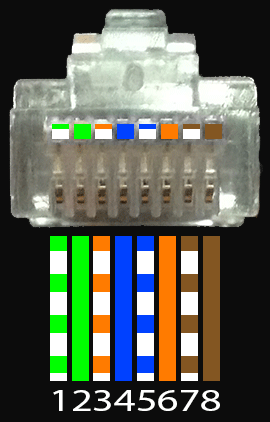
I wrote some code and started making some documentation on the LED wall. I made my OWN repository (we have three now, for the people are keeping track) and got the LED wall up and running. There is nothing to set up you just flip a switch and it will turn on. I did NOT disturbe anything with the current set up, I did NOT rewire anything or change anything that other people were working on. I just unplugged the RJ45 and plugged it into my own connector.
https://instagram.com/p/9znts8A5Un/?taken-by=funvill
Click for video ^^
There is two reasons that the top right two panels aren’t working. There is a wring issue with the panels that needs to be resolved AND the Arduino I have does not have enough memory for all the LEDS on the entire wall while using DMA, there are other methods to by pass the memory problem.
All the documentation is written in a dead tree book that I left at VHS tonight (oops), I will take photos and update this post and MY repositories with documentation and example code.
I am planning on using this with the LED workshops that I have been running as a example project. After the next workshop I will host a hack the wall night to get people started with it.

