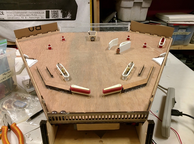
Looking awesome @jon. I like that the balls go down all three of the lanes next to the flippers. I was worries that the gutter would never get used with the bumpers on the wall.
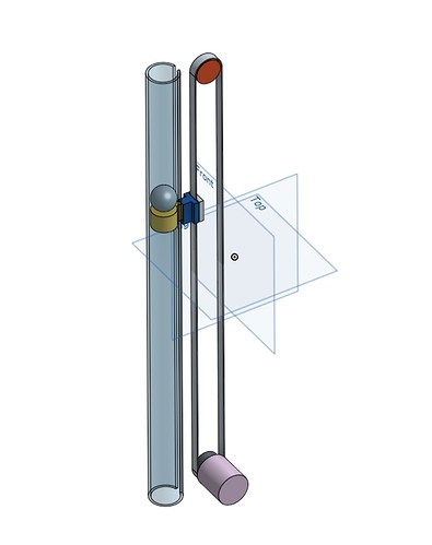
So this is what I was thinking for the center “wormhole” trap/multiball hole
Here’s the onshape file for those who want to give it a twirl:
Essentially it consists of an acrylic tube, with an elevator that rides along a slot in the side of it. The elevator would be attached to a belt driven by a stepper motor, much like the Tinkerine belts in my mind. The elevator would start near the top, there would be a microswitch at the top that would read when a new ball has entered the tube, and would tell the motor to drop down 1 unit (the standard ball height). That way you reduce the amount of impact from incoming balls, and once the tube is filled (this mockup is 20 balls high for a height around 50cm, so could be bigger depending on the space we’ve got available) it’ll reverse the elevator all the way up and spit all the balls back onto the field.
The elevator design can be optimized to make sure that at it’s peak it’s flush with the table surface, in order to close off the wormhole when not in use, maybe while the multiball mode is running. Also it would need some fiddling to make sure it doesn’t hit the upper belt wheel once we know what to use.
I’m still a bit worried about the strength of the stepper motor, 20 pinballs is 1.6 kg, so I’m not sure whether it will have the torque to move that much?
Fibertek has Acrylic rods, so we can even see the pinballs in the tube, I’m not sure where to get the motor, switch, drive belt or wheels, buuut you guys do, so direct me!
Yeah, it would be better to have the tube closer to horizontal, with a curve to push only the balls at the top vertically. Neat idea though!
I’d have no clue how to make that tube though, without buying something flexible or printing something ourselves, and then it would take more engineering to figure out the curved elevator belt setup too (not impossible) I like the idea of having a clear tube though, we could have a window in the side of the machine to show off the innards.
I think this would be a great task for a 3D printer! (the curved part of the tube)
Tonight we tested to see if the flippers, slingshots and coils would effect the WS2812 LED strips that we are planing on using for the table. There was no visible effect on the LEDs.
My next task is to do some demo cuts with the Shopbot for the LED pockets in the playing field.
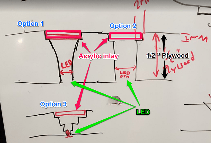
The image below is a cross section of the plywood.
- We will be using 1/2 plywood for the playing field.
- The top of the playing field needs a grove for the acrylic inlay. This will be flush with the top of the playing field. A shelf will be created that the acrylic inlay can sit on top of.
- A through hold will be created and the LEDs will be mounted from the button of the play field facing upwards. There are three different options of ways to cut the playing field.
- Option 2 is two strait holes and will be the easiest to manufacture.
- Option 3 is a stepped reduction to the LED.
- Option 1 is a more genital curve of of the stepped reduction in option 3
- From the top of the playing field looking downwards, The holes maybe in different shapes; square, circle, triangle, etc…
On my front, Connectors finally came in, so am able to setup the test playfield without soldering/desoldering it each time.
I think I’ve resolved the "different flipper strengths issue - I had missed transfering a plastic sleeve from the center of the coil to the one that I replaced, so there was added friction.
@SDY and @packetbob raised some concerns with my power supplies not being up to snuff. @SDY’s offered to lend a large transformer, which will at the very least let us confirm that.
I’m continuing to tweak the layout.
“…Option 1 is a more genital curve…”
Steven’s got lots of balls to claim that, LOL!
I pulled the transformer out of storage at my work, will try to connect one before the weekend and see what kind of DC I can generate, both voltage and current wise.
SDY
The pull in coils are around 3 Ohms so at 48 Volts that is a 16 Amp load (till the end of stroke switch kicks in the holding coil and the resistance jumps to around 60 Ohms (for a more manageable 0.8 Amp)…
Your power supply was rated at 7.5 Amps I think…
The switching power supplies probably don’t like what will probably appear to be a dead short for whatever protection circuit they have…
Perhaps adding a capacitor bank to handle the initial spike may help…
Or ditch the switchers for a simple 48 volt transformer with bridge rectifier that can dump out the needed current…That’s all the game had originally…Just a 100 uF filter after the rectifier…
I have some heavy duty rectifiers if you go that route…
But it will be heavy… Bunch o caps may be much lighter…
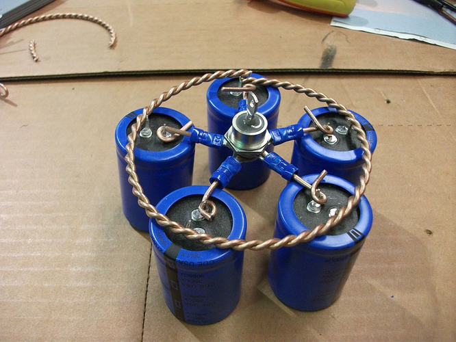
Only 5 amps? Allright, my transformer has been tested and running the appropriate winding at 120Vac, I get about 65Vac out of it, which when rectified should be about 50Vdc. The capacitor bank is 5 X 2700uF/200V, individually wired so as to lose only a minimum via resistive loss. The transformer VA rating is 750, 'should be more than OK.
That’s a piece of art!
awesome!
Spent some more time on tweaking the playfield layout. Here’s where we’re at (the center and right side) :
Highlights -
- center captive ball (hit the trapped ball and it will fly into a switch behind it)
- inner lane shot that directs the ball either to the opponents side or into a rubber bumper
- outer lane, shootable from the opposite flipper, up and over, or via the slingshot
- narrow standup switch target to the right of the lane (needs to move over a bit further right)
on the whole I’m pretty happy with how it shoots - I think I will start to translate this back to the CAD model, and it will be mirrored for the left side.
I will be dropping off the basic power supply tomorrow, Tuesday. I might add some work to it (it could use some blue LEDs… And an analog meter to indicate the state of charge of the capacitors… "Scotty! I need more power! “Keep your shorts on, Kirk, them flippers were abused, them flippers will have to wait 637milliseconds!”). It is mounted on a steel shelf, along a couple of fuse blocks, and I am bringing another identical shelf if you care to use them for all the different supplies you might be using in the machine.
Thank you!
I’ll be there tommorow night.
We tried the new power supply last week - to mixed success.
The two voltages on offer are ~43V, and ~86V.
43V was unfortunately a bit below what we where hoping for, and even with @SDY’s beutiful capacitor pentagram, we had noticeable sag when more than one thing would activate.
Unfortunately 86V caused some scary arcing noises under the playfield when we tested it, so that seems to set our upper bound.
So we resorted to adding more capacitors. That big 10000μF one on the part shelves finally got a use! Before testing, we had neglected to change the voltage back to the lower voltage.
I had never heard a capacitor make clicking noises when it recieved power, which was one to add to the “let’s not do that again” list.
After lowering the voltage, we found that the capacitors did help, but we needed more.
Fortunately, we found some:
I’m very much out of my depth on the power side of things, many thanks to @SDY for all his help!
Still making progress!
Took the placements from the prototype, measured, and added to the CAD model. Current rendering:
Interactive model: Fusion (this link isn’t a snapshot in time - it get’s updated as I make changes)
I also quickly built and prototyped an ugly spinner:
to test how much it reduced ball speed. Good news - not very much. There’ll be 6, 2 on each side - in those ‘lanes’ with a semi circle below them.
Still to come:
- switches/sensors
- central triangle
- Ball Feed mechanism
- lights
- artwork.
- Assembling the panels together
- scoring/rules.
We also noticed that the layout ended up looking snake head-ish on the three sides - that might become the theme…
What happened in Nov!
Detecting the ball - tried out an inductive proximity sensor that’s intended for a 3d printer. Detects the ball very well, but not a huge working range. Very compact easy to install package, so I’ll probably be going with something along these lines. Aliexpress seems to have detectors rated for a longer distance, but if push comes to shove, mounting them through the playfield will be fine.
Lighting - the LEDs showed up.
With the sensors and LED size figured out, we’re starting on figuring out the placement under the playfield.
In the new-year we’ll be making prototype 2 - in real thickness, and getting things up and running under the controllers.
Progress on this project hit a wall in mid December when the laser cutter went down, and most of my free project time went in to getting it back operational. Since then, I’ve plaid around with a few different positions for the Lighting inserts and proximity sensors.
After a few iterations on paper, I went and put them into the CAD model (as usual, the latest version is visible here) I also roughed out the centre triangle a bit more. The ball raising mechanism still hasn’t been designed, and nor has a mounting frame or assembly.
Next step would be to cut out whitewood two with half inch ply, move the components over, and start working on the lighting/detection/scoring for one side, and then on the centre and ball lift. It’s also at the point where art is ready to be be considered.
Unfortunately, this project is on hold indefinitely at this point, as I’m moving away from Vancouver for work, and unsure what resources I’ll have to continue it. I do intend to return to pinball machine building when I can.
I’m extremely grateful to all who helped it get this far, @funvill, @packetbob, @SDY, and @Jarrett, and I’m sure others have all chipped in and made it possible to get to where it has.
If anyone who donated components would like them back, please let me know, and we can make arrangements.
It’s sad to me that I won’t be able to demo this at maker faire anytime soon, and I’m disappointed to let down those who chipped in and contributed. Unfortunately, real life just … got in the way.


