New Pinball Project

when last we left our intrepid heroes

I’ve started to settle in in Toronto, and found the necessities of life - lodging, power, internet, and, tentatively, a maker space. It is a truth universally acknowledged, that a maker in possession of a good makerspace membership, must be in want of a project to try out their resources. I’ve got a few things on my projects list (don’t we all?), but for all the reasons that the pinball table fascinated me in the first place, it’s drawing me back.

They don’t seem to have much of a web forum presence, so I figured I’d keep using talk until I get around to setting up a blog.


First question - why start over, rather than continue the previous project?

Primarily, I ended up feeling that the multiplayer pinball concept created a lot of challenges that were less interesting, and entirely additional to, the inherent difficulties of a custom pinball project.

  • The ball feed mechanism was going to be a giant hairy mess - we’d be essentially building most of a fairly complicated Rolling Ball Sculpture to feed balls onto the table. From my research, these are both notoriously finicky, and unreliable.
  • Frame / support - a traditional pinball cabinet is quite simple, basically a box with a slanted top, due to the large size and separate panelized nature of the multiplayer design, this was going to require some clever design, and a fair bit of work to fabricate.
  • scoring/game logic. There’s a surprising amount of resources for custom pinball software - the Mission Pinball Framework is an opensource framework that saves a lot of time on the common game management logic of a traditional pinball machine, but it wouldn’t have been feasible to adapt it to the multiplayer design.
  • scale and transportability - the multiple panels caused a large physical size, which was difficult to pull out/put away as it was worked on.
  • cost - having to buy 3 sets of everything drove the projected costs of the project sky high.
  • etc.

There’s lots of things with a traditional design that things have an “off the shelf” solution. That’s attractive in terms of actually delivering on a very large scope project.

A final aspect is that I ended up a bit disappointed with the constraints in how the machine felt to play. It was designed to get by on novelty, not provide a deep playing experience. The wide open layout contributed to this. This was an explicit choice I had originally thought was a clever way to reduce the pressure on the playfield design, but in the end I kind of regret it.

I may return to Tri-Orbital Terror, and it’s general design, but for now, I want to take a crack at a more traditional game.


Starting Over.

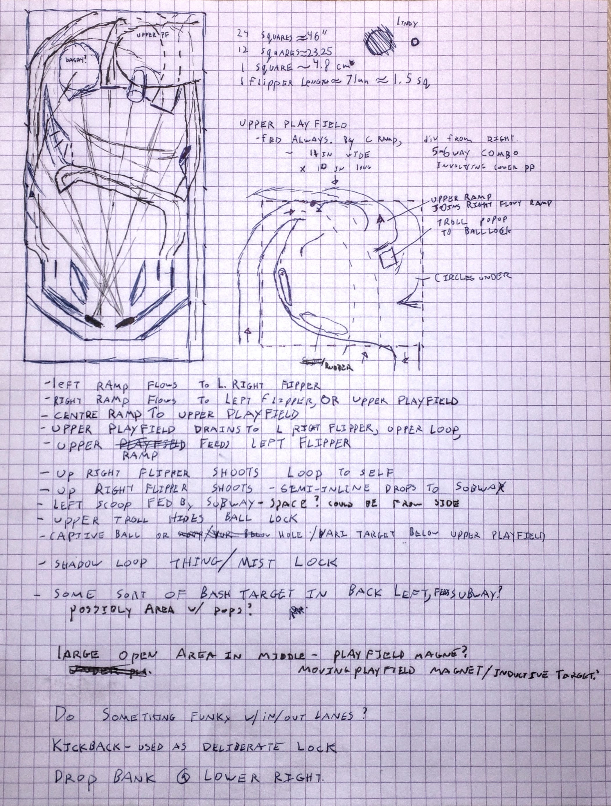
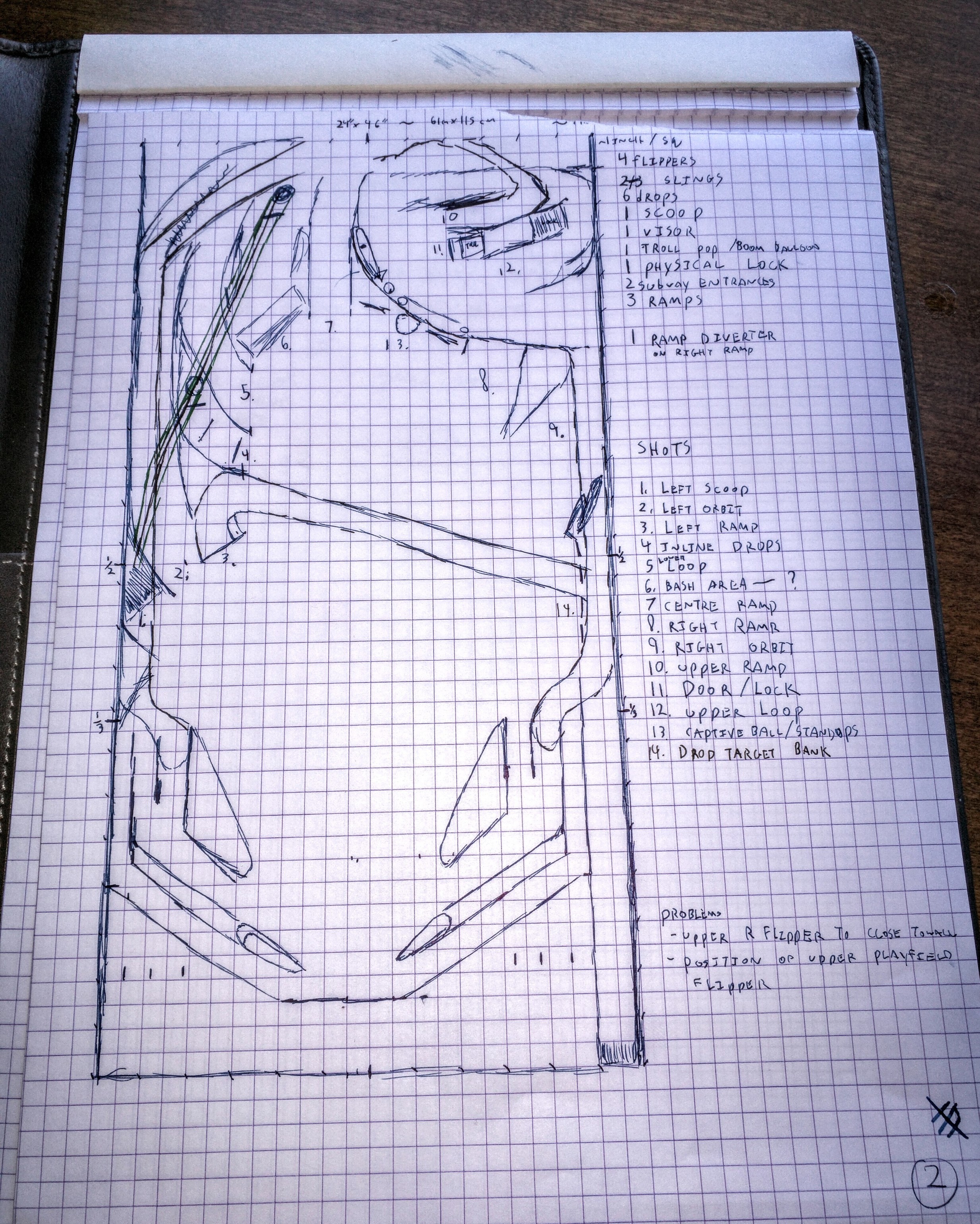
So, here’s some thoughts I started with to start sketching out a new design.

  • Generally traditional size/layout.
  • There’s two common sizes of pinball table, both are 45.00" long. “standard” width is 20.25", “widebody” or “superpin” size is 23.25".
  • I’m currently planning widebody, as it gives more room for mechanisms under the playfield, etc. Building from scratch in quantity 1, the incremental costs of widebody appear pretty minimal.
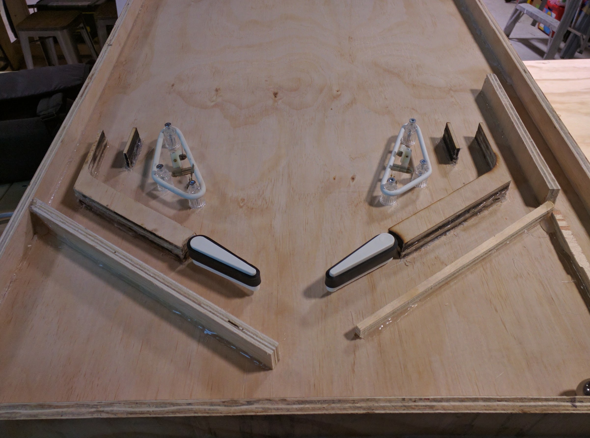
  • Game should “Flow” - shots should feed other shots, most shots should keep things moving. include Ramps.
  • Shot based games - aim the ball, don’t just toss it into an area of the playfield.
  • Theme will be a later decision, but plan on doing it as a fan-work, using an existing theme, rather than custom artwork (this approach seems really common for custom pinball machines.)
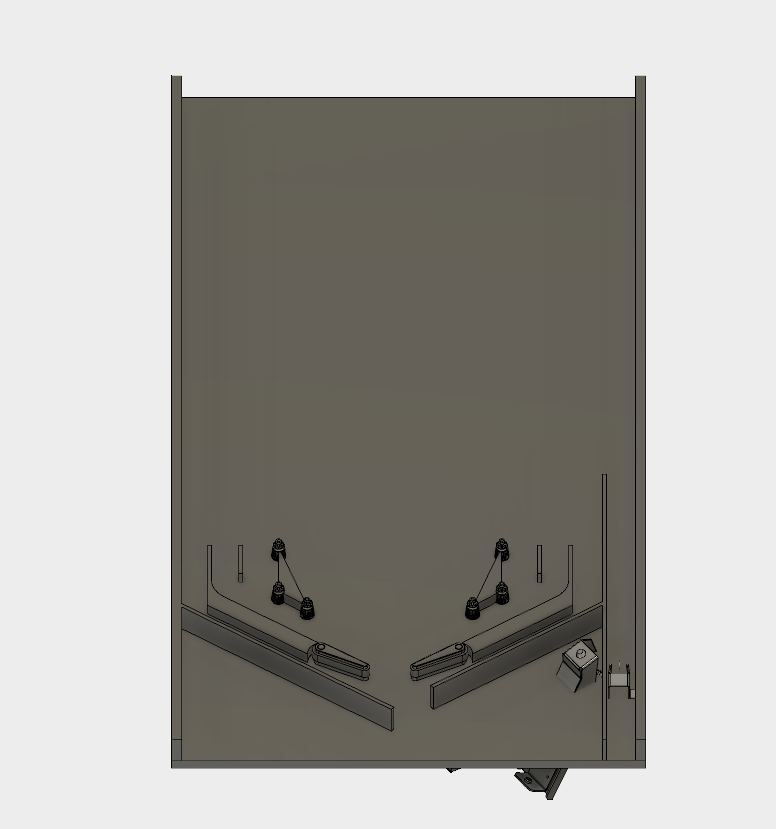
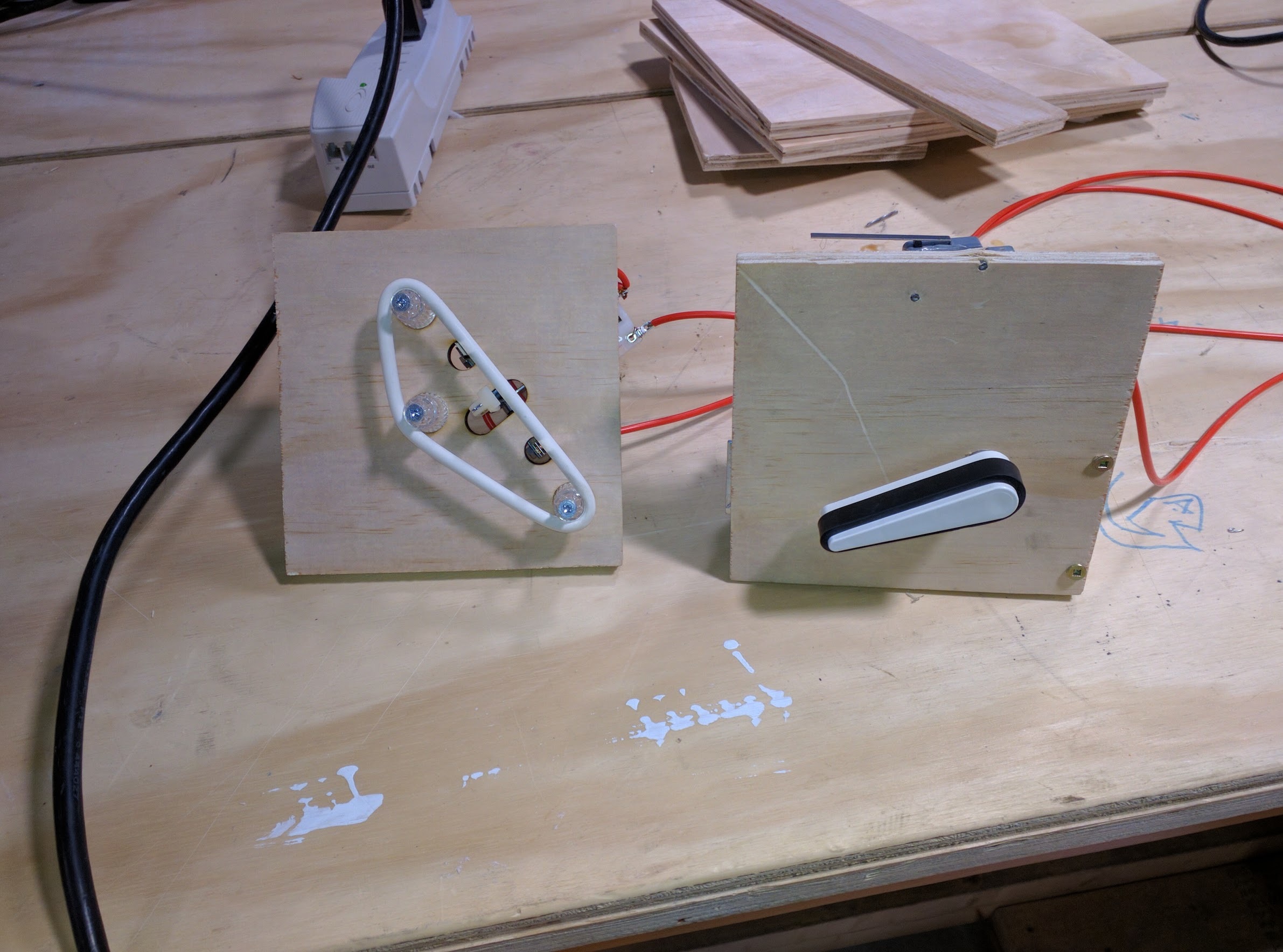
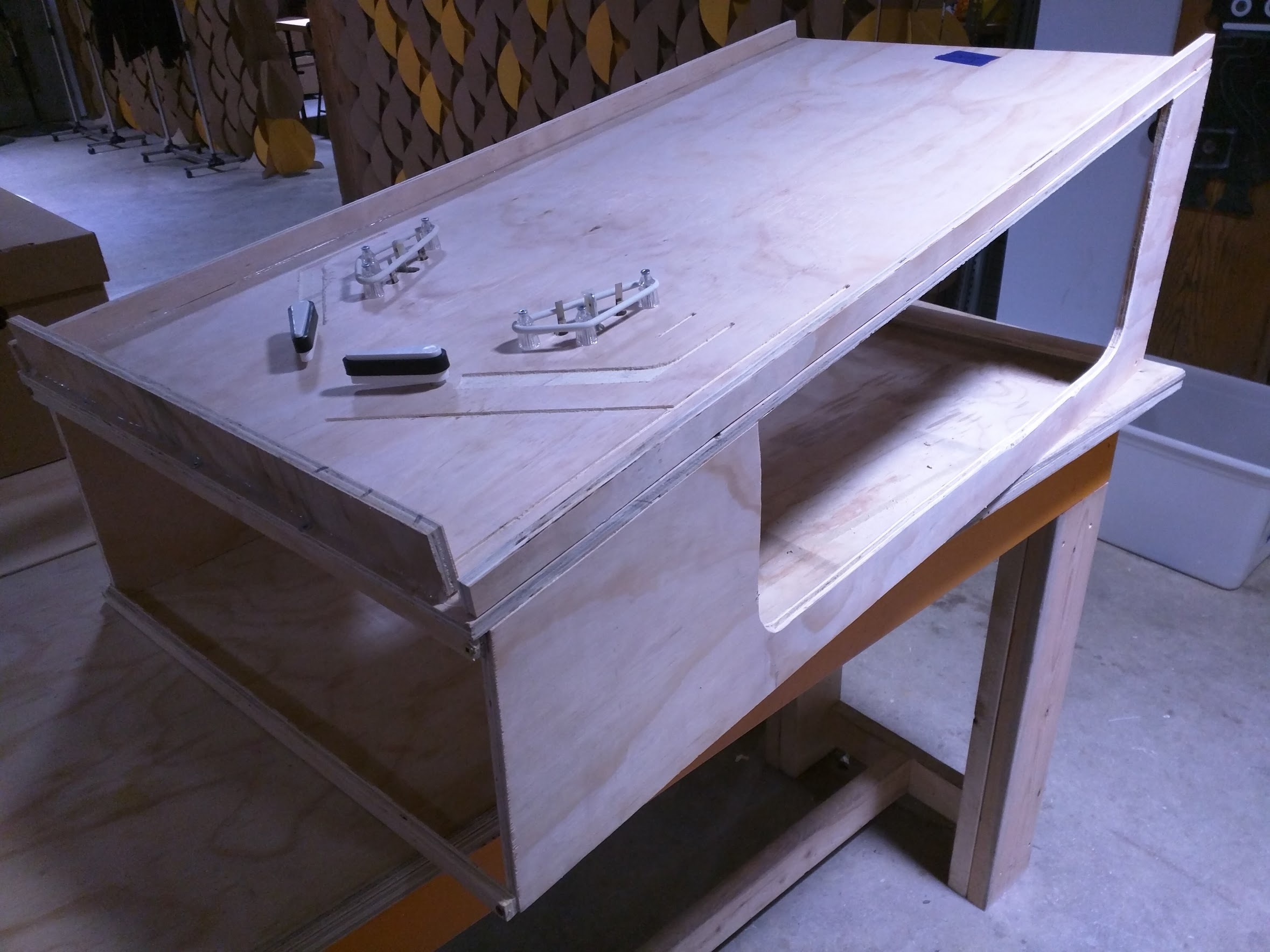
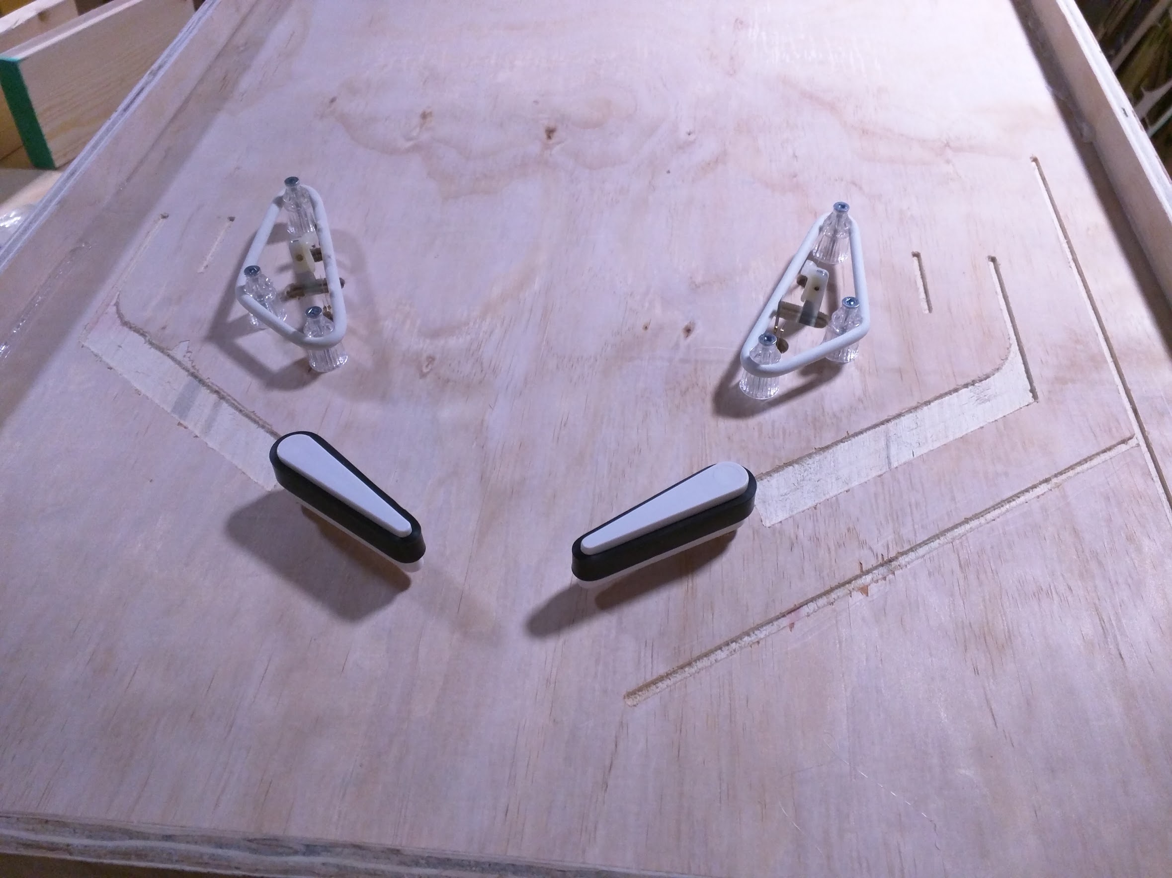
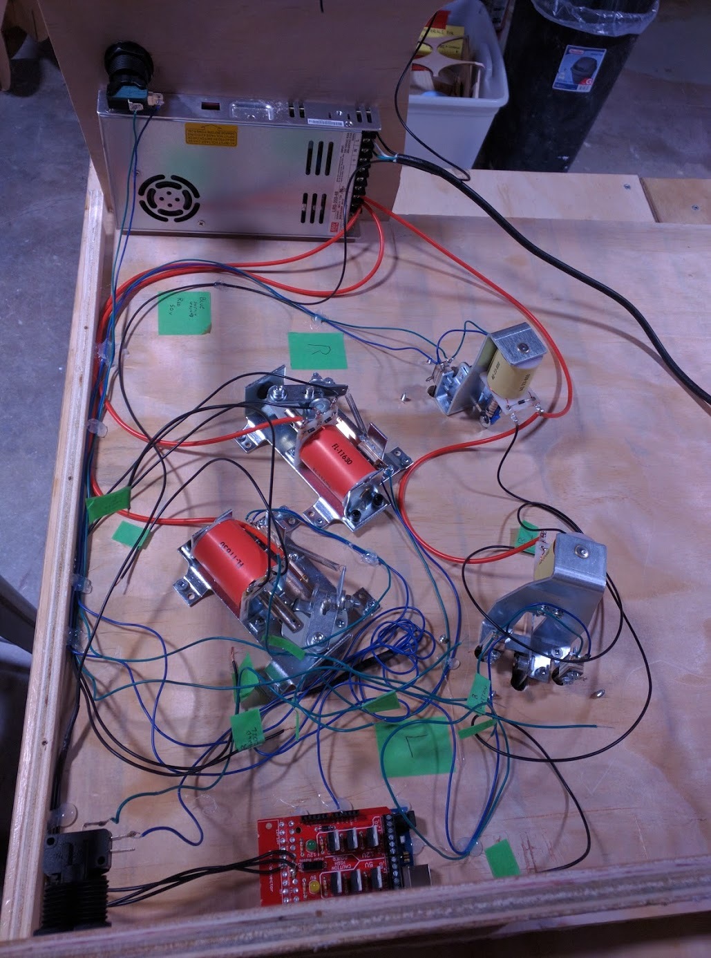
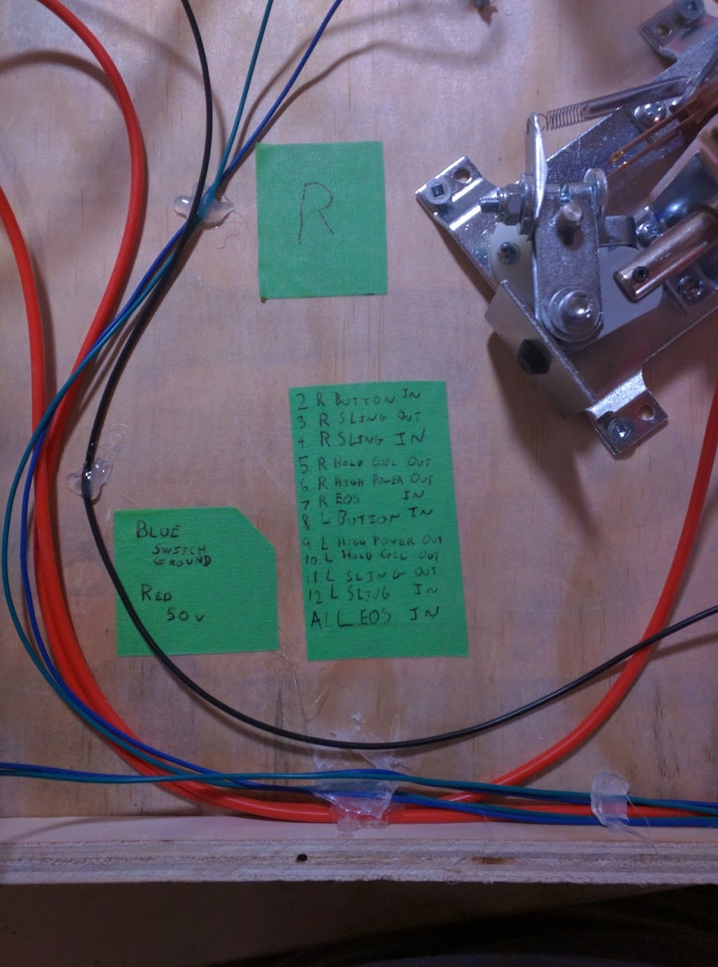
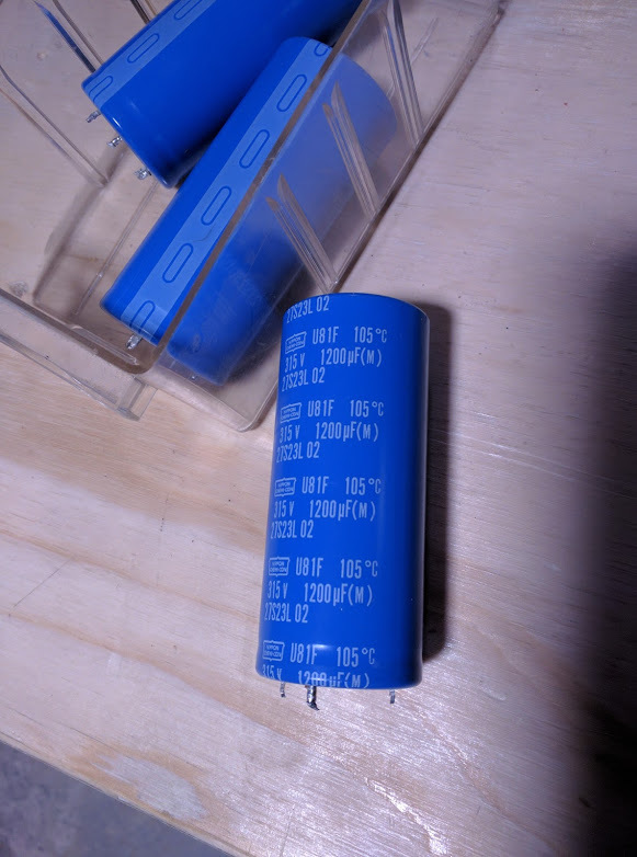
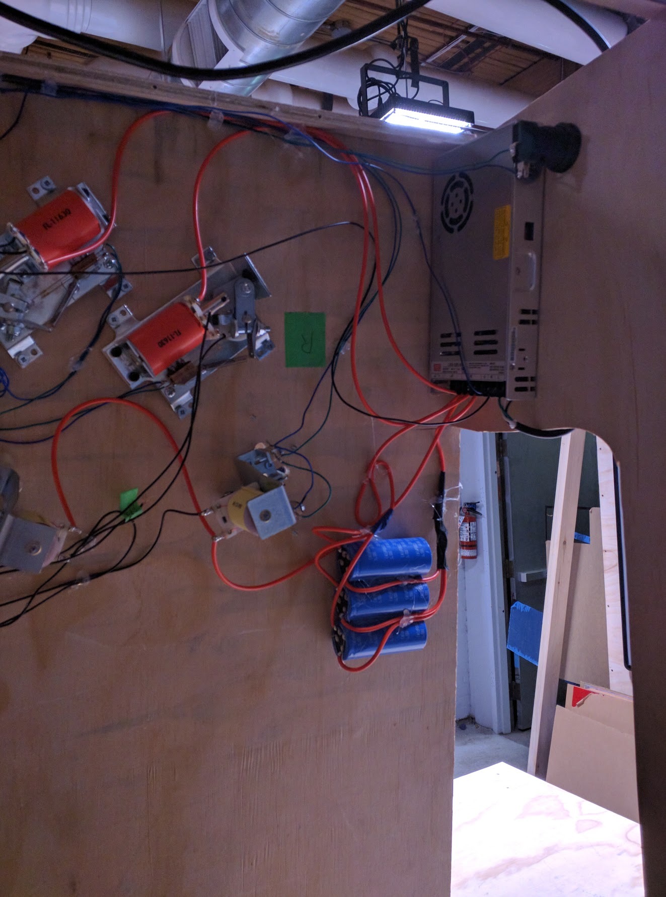
  • Start with prototyping the shots and layout with just hardwired flippers, switches and a power supply - worry later about electronics, scoring and control.
  • some half-assed ideas for mechanisms I wanted to use.
6 Likes

That brings us to the first sketch

The upper left is ~to scale 1 square = 4.8 cm. roughly sketched in are “shot lines” of what flipper a shot is primarily fed from, and where they return to. I didn’t worry too-much about size and absolute positioning of shots, this is more about figuring out relative position.

You can see that there’s an upper playfield at the upper right, which is called out in more detail to the right of the main diagram.
Some thoughts are noted at the bottom of the page.

After the first drawing, I took the rough layout, and re-sketched out the diagram, larger.

Drawing 2:

This isn’t a great sketch, but you start to see things a little more clearly:

  • the lower main playfield is fairly traditional and symmetric - two inlanes and an outlane on each side, normal sized slingthots, etc.
  • A flipper on the right of the playfield, about midway up.
  • a scoop at the lower left (labeled #1 in the diagram) is fed from a subway (a small plastic trough under the playfield) from two upper shots.
  • Left and right orbit shots
  • There are four ramps on the playfield:
  • The left ramp (#3), which feeds across the playfield to the right flipper.
  • The center ramp (#7), which feeds to the upper playfield.
  • The right ramp (#8), which feeds to either the upper playfield, or around the back to the left flipper.
  • An upper ramp (#10), on the upper playfield, which feeds to the same left flipper return as the right ramp
  • The upper playfield drains down to the right flipper.
  • There’s two main shots from the upper right flipper
  • a loop around to the same flipper (#5)
  • a line of drop targets that feeds to a hole and the subway(#4).
  • There two ‘dangerous’ areas, where the ball will hit things -
  • under the upper playfield, between the center and right ramp (#13)
  • A “Bash Target” area to the left of the center ramp (#6), that will in someway interact with the ball, and be able to drop it into the subway.
  • On the upper playfield, there’s currently Three shots. I’m not sure if there’s going to be enough room for that.
  • the upper ramp (#10) (See above)
  • an upper lock shot, where some controlled target blocks the lock. (#11)
  • an upper loop (#12) that loops around back to the upper flipper. This will be cut if there’s insufficient space.
  • Some drop targets on the lower right.

There’s some clear issues with the design:

  • the position of where I have the upper right flipper is too close to the right wall for the underplayfield mechanism
  • the upper playfield design needs fiddling with.
  • The bash target area has to be designed at all.

some example combo shots:

  • Left Ramp → right flipper → center ramp - > upper playfield → upper ramp - > left flipper - > right ramp → upper loop → upper lock.
  • left ramp - > right flipper - > left orbit → upper right flipper - > loop → upper right flipper - > hole
  • right ramp → left flipper → center ramp → upper ramp → left flipper

I’ve started to put the rough design into Fusion, to start making a test playfield.

In parallel, I’ve placed an order for parts from Pinball Life:

[spreadsheet of parts] (Pinball Project Parts - Google Sheets)

Flippers and Slingshots, along with a kit of rubber and an assortment of metal and plastic posts and standup targets for prototyping on the playfield.
I also ordered a spinner mechanism, and a playfield magnet to try out as things progress.

What makerspace in T. did you settle on?

For no particular reason, you should have a camouflage area with a floor
that looks like this:

http://www.wheelfanatyk.com/wp-content/uploads/2014/12/ball-bearings.jpg

steamlabs is right around the corner from work, and has a big laser cutter and CNC. I suspect I’ll end up spending some time at site3, as well.

Created a fusion project, got a basic lower playfield modeled.

Here’s the link to the viewable Fusion360 model of the playfield. AIUI, that’ll always link to the current version of the playfield, so here’s a snapshot of the current look of things:

  • I grabbed a bunch of the open models of common playfield mechanisms (flippers, flipper mechanism, trough, shooter, etc.) from PinballMakers.
    • They’re just roughly positioned at the moment, and I haven’t put cut throughs for the trough or shooter, as I don’t plan on cutting them on the first white wood. Just want them roughed in for context.
  • I’ve learned a bit more fusion best practices than when I started the last project, so this time it’s far more parametric, and split across more independent sketches and bodies, which seems to greatly improve the performance.
  • Digression - I need to do some reading/tutorial on rendering out of fusion - this is just a screencap from in edit mode, rather than render, as it looked better to me.

The CNC router here isn’t yet available to get trained on, but the laser cutter is big enough to get the entire playfield into. I think I should be able to cut 1/2" plywood acceptably with it, but at least for now there’s only two circular holes all the way through (the flippers), so I’ll just etch the positioning into the surface, and use a drill. The rest of stuff all builds up on top of the playfield, so I’ll laser cut it, and glue it on top.

For power supply, I did some research on what others are using, and it seems that the common approach is a ~300+W 48V SMPS. Poking around Mouser a bit, This Meanwell one seemed reasonably priced.

So, lots of stuff currently winding it’s way through the postal system to me, and the playfield’s ready to cut the first revision. (pinball prototype’s are traditionally called “whitewoods”)

For whitewood 1, this time I’ll be trying to use full 1/2" plywood (the savings of using 1/4" last time were not worth the difficulty mounting things through half the proper thickness). I need to find a local lumber yard. For prototyping the upper playfield, I’m mostly planning on using foamcore/plywood and hot-glue, tweaking until it shoots well, and then measuring it into the fusion model.

Parts showed up from Mouser (power supply), and, after a week marrinating at customs, Pinball Life.

After assorted adventures in inadequate means of transporting plywood, I managed to get a 4x8 sheet worth of 1/2" plywood back to workshop. Conveniently, the playfield is just under 2’x4’, so a quartered up panel works nicely.

First things first, I wanted to test my measurements and design for the main mechanisms - the flippers and slings.

Took two small pieces of plywood, cut the patterns into them, and mounted up the mechanisms, then wired them up. My previous plan, to just trace points had forgotten about the slingshots, which have a slightly more complicated mounting pattern. Fortunately, the laser handled 1/2" reasonably well.

The design of the slingshot mech is such that it appears that it will always bounce the switch after firing, which is “not good” for the switch/solenoid/power supply. I think for now I’ll just throw a micro controller and two relays on for enforce a couple second switch debounce time.

The flippers need one minor bit of re-working (reversing the leaf switch, and bending it to normally closed) to run with mechanical power control, as shown here. This’ll be fine for now, when I decide what I’m doing for the real controller, I’ll flip the switch back if necessary. I neglected to include arcade switches in my order, but I can buy those locally. For now I’m using a microswitch on the test rig.

Next issue to resolve is how to mount the table at ~7°, while still being easy to flip over to work on the underside of the playfield. I think I have an idea for a good way to achieve this…

1 Like

Since Saturday, I got two evenings working on the table in.

The first evening, I was able to get the playfield cut on the CNC. I cut a small lip for most of the playfield geometry, to make it easy to position when I cut those pieces on the laser.

The CNC has a vacuum hold down, which is quite cool.

To mount the playfield at the proper angle, while providing for storing and working on it, I again built a frame. This time, the frame is screwed to the playfield, and more full size. It actually ended up bigger than is probably necessary or ideal, but that can be fixed later. This allows the table to be stood upright or on it’s side to get at the bottom, or stood on it’s side, and upright for storage.

I also populated the lower playfield mechanisms (flippers, slings). Here’s a closeup that gives a good view of the routed in lip to mount the lane walls to.

Next step is to add the lane walls and wire the flippers and slings to power.

4 Likes

Spent two sessions wiring up all the flippers and switches. Wiring always takes longer than you expect.

No photo, as I was in a rush packing up. I’ll add one later.
My wiring is a huge mess, all run point to point. For the next revision, I need to be more systematic with wire runs, or something is going to get damaged.

After doing some reading, it seems that new leaf switches in assemblies aren’t built with the expectation of taking high voltages, and will pit very quickly. The slingshot switches are also mounted in such away that physical debounce from the rubber when the sling fires seems un-avoidable - I’ll need to do generous software debouncing.

To keep things moving using local suppliers, I picked up one of these mosfet driver shields. When they say “This shield allows you to use a computer power supply (or other power source)” I appears the actually mean “this shield has an ATX connector, but with a bunch of desoldering you can use another power source.”

I currently have 6 switch inputs (2 flipper buttons, 2 flipper end of stroke switches, and 2 switches per slingshot wired in parallel.

There’s only four solenoids currently (2 flippers, 2 slinghsots, but the flipper solenoids have two taps- high power (~4Ω) and hold (~160Ω), in series, so 6 points I’ll need to control.

I’m running the grounds through the drivers for the solenoids, and using the internal pullup resistors on the arduino for the switches.

I’m almost done wiring this up, then need to cut and glue the rest of the lower playfield. Once that’s done, I’ll throw together some quick arduino code to drive the flippers and solenoids, and fire her up!

Hopefully not literally.

1 Like

I don’t know if I’ve mentioned this to you, but I bought a pile of assorted quadcopter connectors to help out with point to point stuff in some of my stuff.

It’s okay. Sure beats soldering everything together.

2 Likes

Finished wiring it up to the arduino & shield

Here’s the general mess:

I wired everything to the shield. The high power lines have screw down blocks, but the rest is in the pin sockets. To prevent anything accidentally dislodging, I ran a bead of hot glue across the socket - can easily be peeled off, but should prevent anything from falling off accidentally.

The low voltage stuff (switches, the arduino) have their grounds tied to the 50V power supply.

Here’s the notes for where stuff is currently wired:

(this is posted here mostly for if that piece of tape peels off, I now have a record of it…)

I’ll finish throwing together some simple code with safety timeouts, then should be able to test it out, probably this weekend.

2 Likes

nice jon…

Fired up the board with some simple driver code to test the slingshots - I haven’t looked at the flippers yet.

Discoveries - the power supply holds a charge after power is cut for a shockingly long time. Like, enough power to fire one of the solenoids after it’s been unplugged. This was a “rather exciting” discovery. I added a 1kΩ resistor across the power supply. That value was chosen entirely based on what was handy at the moment - there’s probably a better choice. Judging by the LED on the power supply, voltage drops below the level capable of running the LED within about 3 seconds now.

I also managed to blow one of the MOSFETs on the driver - it failed short, firing the slingshot immediately when plugged in. This was oddly hard to find when I was first looking, as everything tested correctly, but on second test was very clear - probably a poor connection when I was testing with the DMM. Thanks to @Jarrett and @TomKeddie over on #random-projectry for their suggestions.
Correcting this was made more difficult by my previous half-assing - the board was thoroughly hot glued down, and some of the connections were soldered to it. I was able to pickup a couple replacement MOSFETs locally, so resoldered one. Steamlabs doesn’t have any de-soldering tools, flux, and only lead-free solder, so that was more tricky than it should have been. I’ll bring some of my own supplies for next time.

Next will be re-testing the slingshots, then writing some code and testing the flippers. Hopefully not blowing any more MOSFETs, although I do now have spares.

2 Likes

Not a lot of progress, as I struggle with the electronics.

I laser cut the lower playfield features, but haven’t mounted them yet.

On the electronics front, It’s been mostly frustration.

The big discovery was that the slinghsot coils are lower resistance than I thought, so when fired on were drawing ~ the max rated current of the power supply. So it became super sensitve to the exact firing timing and how long the switch was closed - the table stood on it’s side would work, and laying flat wouldn’t, which had me tearing my hair out (leaf switches and gravity - the switch wouldn’t be held closed for as long if it was on it’s side…)

I eventually noticed that the light on the power supply was going off, and once it went off had some sort of protection circuit that would keep it off for a few seconds. This explained the inconsistent behaviour I was seeing.

I’m going to PWM the slingshot solenoids down a fair bit, and see how that helps. I’m also going to grab a few Big Ass Capacitors that are lying around the lab, and throw them on.

They’re 1200μF 315V caps. 4 pins (presumably two are for mounting strength?). There are three of them.
My bleeder resistor also let out the magic smoke, so I’m going to have to do something a little more proper there.

The electronics side of the project is frustrating, as the current setup is intended to be a temporary state, some open source controller boards that I backed on kickstarter are supposed to arrive late in August (and are showing signs of being on time so far?). The boards support the Mission Pinball Framework, which is an open source python framework for pinball games. I want to avoid putting too much time into the current electronics, as almost everything will be changing.

Hopefully with the caps and PWMing the power down, the slings will work consistently, and I can move on to the flippers.

2 Likes

Over the weekend, I mounted the lower playfield guides and the capacitors.

Tonight I fired her up with some tweaked code that PWMd the power to the slingshots down to 80%

And it worked.

downsides I cut the slingshot holes a little too far back from the rubber, so they aren’t as responsive as they should be, and the fire timing needs tweaking (I’ll probably just wait until I’m running the final boards, which should have reasonable defaults).

TODO: fix spacing of the slingshots in the CAD model.

I’m not going to re-cut the playfield right now, the slingshots are good enough to move on.

Next on the list - getting some basic code together for the flippers.

3 Likes

More electronics issues.

The flippers gave me no end of troupe with the driver board I was using. Any time I’d try to fire two devices at once, I’d burn out a solenoid. Multiple experiments with different PWM levels, full power timing, staggering the full power of the left and right, etc., it always seemed to kill a MOSFET. Repeatedly replaced and tweaked, but without much luck.

As of last week, I was left with a table that would almost immediately blow it’s drivers if looked at funny. Very frustrating.

However!

Back a month or so ago I said:

In a shocking departure from the norm for kickstarter projects, the Open Pinball Project boards I backed shipped last week - more than two months ahead of schedule. After some time lost in the postal system, they arrived in my eager hands yesterday, ready to be soldered up.

Knowing they had shipped, I decided to cut my losses on the current board and replacing parts on something that is evidently not designed for the task, and start working with some parts designed for the purpose, to eliminate that side of the problem.

Hopefully this’ll speed up progress.

2 Likes

Woot! That’s awesome those boards shipped ahead of schedule. Looking
forward to seeing more pics. Things look great so far.

I ran into issues with having space where I’d have enough room to work on the table, so the in progress playfield went into my storage locker for a few months. I did solder up some of the open pinball project boards, but hadn’t tested them.

I now have a shared shop with a few people, so hauled it out of the locker in preparation for resuming work on it.

So far, I pulled all the wiring off the existing parts - it was in a pretty sorry state from my attempts to debug the previous electronics issues. I’m ready to start re-wiring.

Some resources popped up my last post:


A guy gave a talk at CCC about building custom pinball machines.
Interestingly, he built a head to head machine, along the ideas of my earlier Tri-Orbital Terror project. There’s some interesting resources.

Video Here


Someone added very good documentation to Pinball Makers on the Open Pinball Project boards. This clears up a lot of questions I had from the initial documentation.

2 Likes