VHS Group project - Multiplayer Pinball

Progress Update:

Rebuilt the entire thing in Fusion 360, so that I wasn’t dependent on the hackspace solidworks machine.
Took an initial crack at modeling the lower playfield/flippers area, and been toying around with other object positions.

Current Rendering:

5 Likes

This is a thing of beauty. Thanks for the update pic.

I’m liking Fusion a lot so far. I’m trying to use their online project/wiki stuff for notes, links and ideas for the project. If anyone wants access to join, let me know.

Mucked about in Fusion, getting an assembly going, and playing around with pop bumper placement. You can see an interactive model here.

2 Likes

Everyone try the explode tool!

1 Like

I am helping on this project with the controls system and lighting.

The requirements

  • All three player panels will need 9 outputs, 15 inputs each. (Total of 27 outputs, 45 inputs, more is better) The outputs must drive 5v 20ma replays, the inputs are normally open limits switches.
  • The status of the inputs must be read by the central device running python.
  • The outputs must be controllable by the same central device running python with a 1 sec switching frequency.

The plan

At first I wanted to use a Arduino pro mini per player board and connect them to a central bus that would be read by the Raspberry PI. The main reason that I wanted to go this route is that I have a few dozen Arduino pro mins with screw terminals already, less equipment to buy. The problem is that the Arduino pro mini only has 20 pins per board. I could multiplex the inputs but I wanted to keep the wiring simple.

The Arduino mega 2560 has 54 I/O pins and should be more then enough for all the boards together. The mega can be purchased for as low as $7 USD from AliExpress. A sensor shield that breaks out all the pins on the Mega costs an extra $6. I was hoping for a screw terminal shield for the mega but there don’t seem to be any available on AliExpress. The boards are so cheap I will probably end up getting three of each board and installing a board on each “player panel”. This will give me lots of extra I/O if we decide that we need it, and redundancy if one of the Arduinos fails on site.

Next I plan to install the firmata firmware on the Arduinos. This will give me serial access to configure and access the I/O pins on the Arduinos. The great thing about the Firmata protocol is that I can change the way the I/O pins work on the Arduino remotely via serial commands. The same firmware can be install on all the different Arduinos making them dumb I/O boards.

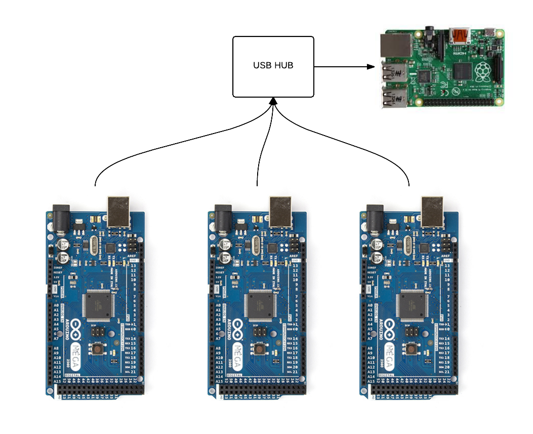
The three Ardunios will be connected via USB serial to a powered USB hub. The Powered USB hub is connected to a central Raspberry PI. The Raspberry PI will then be running python, and the pyFirmata python library.

I plan on using the LED strips that I purchased from AliExpress for the dome project. We are still thinking about how many LEDS we will need. We are guessing that we will need less then 480 pixels.

As always suggestions are welcome.

Driving 9 outputs @ 20mA each is very close to the Absolute Maximum current per Vcc/GND pin (200mA) for the AVR, I would not recommend this though it will probably work. You haven’t mentioned them, so will also add that since you’re driving relays you need flyback diodes to protect the microcontroller. Most of the relay “shields” I can see out there only have 4 relay outputs, are you planning to just airwire these? Do you actually need relays (for nostalgic noise, handling AC or small signals, etc)? FET switches might be easier and cheaper depending on the load.

I don’t know anything abour firmata (though it looks pretty interesting), but I would be worried the various latencies plus polling interval in this architecture will cause you to miss input events. I didn’t see a way to set up interrupt semantics in firmata (even if it is just doing polling in the firmware).

You can cut down your Arduino requirement by 1/3 if you split them by input/output function instead of by player board, assuming your I/O requirements don’t change. Should also reduce serial/USB traffic somewhat. May make the code a bit uglier on the client side, and if you don’t want to risk running the device at its Absolute Maximum, you’ll also need to add relay drivers to the output board, but you should do that anyway ;).

1 Like

Hmm, I think we lost something on the output side- we had wanted to be able to PWM the solenoids to control power, so I don’t think the relay outputs where the plan. @Jarrett was building a solenoid driver for us - what were you expecting for control?

LEDs- IIRC the strips that you have are the flat ribbons, aren’t they? when we had discussed it, we talked about this style so that we’d be able to mount them easily.

Firmata looks like a nice solution. I’m not super concerned with latency, and it looks like we could buffer input on the microcontroller side to avoid missing inputs?

On @ktims 2 arduino suggestion - with the price/controller pretty low, making the panels as independent as possible is a nice feature to have, certainly worth the $20 to me.

1 Like

I will have some solenoid/coil/motor/whatever drivers coming. They are very general, so they can take a 5v input (low current, 4mA should be safe), and switch a high voltage on the output. Depending on how you spec the MOSFETs, you can use them to drive up to 90v/10A or so. A solid 5v input or a PWM input is fine, which could be used to drive a solenoid open, and then lower the average power delivery just enough to keep a solenoid activated but not burn out.

Unless you’re doing something special with the relays, these can replace them. They don’t sound as satisfying, though.

I have 30 coming and I need maybe 6 of those. If you need more, I can panelise them more efficiently, if you’re willing to wait a month after the first batch arrive and get tested (so, 7 weeks from now). They’re also simple enough to protoboard if you’re in a rush.

2 Likes

they can take a 5v input (low current, 4mA should be safe

Great, sounds like that takes care of the concern for how much current we’re running through the microcontroller.

They don’t sound as satisfying, though.

They’ll be firing solenoids - you wouldn’t be able to hear the little click of the relay over the big thumping click of the solenoid anyways :smile:

We won’t be building out all three sides to begin with, just one side + center to test and workout kink in the design and layout - lead time on the rest of them isn’t a problem.

Current plan for power supply is 48V - and rather less than 10A per coil!

1 Like

This project looks fraking amazing! I don’t really have any time on my plate, but I’d still love to help out if there’s slack to be taken somewhere. Certainly would love to learn some electronics.

For my input on the design, It would be awesome if you had a hole right in the center, for multiple uses, could be the jackpot hole as well as a multiball dispenser, perhaps both at once? Imagine slowly stacking your balls in the center hole, every time you get one in another gets released to take it’s place, once you’ve got 10+ stacked up in the hole a piston pushes up, spitting them all out on to the field.

EDIT: If you guys want custom resin parts for decoration (a long ways away) I’d be happy to help, would be neat to have some unique bumper toppers.

Yes, you are correct. I linked to the wrong LEDs. These LEDS also use WS2812 chip in them so it will be the same principal.

I have used firmata in past projects, they use a hardware interrupt for the pins (as far as I can tell) so they announce when the change of a input happens and sends it down the serial line. You client device doesn’t need to POLL for the present value of an input, the values get PUSHED. although there is a initial POLL for the current status of all inputs on start up and “key frames” POLL periodicity to ensure that everything is how you expect it

Sweet! Thanks @Jarrett
.

@jon did a shitty photoshop edit, cause it looks so cool. I have a hard time knowing the scale of the thing so it’s tough to know what sort of room you have to put obstacles.

Those ugly blobs in the edges are meant to be those rubber band sort of bumpers, similar to : Image

@Gibbtall - sweet, great to get someone else on board, especially on the making stuff look better front!

We’ve definitely talked about putting something along the edges to throw stuff back towards the flippers - still playing around with exactly what.

It also might not be clear but the thick ovals above the flippers are going to be slingshots (what you linked) - with the playfield being triangular, they actually should be straight to kick things up and to the sides.

The general costs on active elements goes up in a hurry - active slingshot mechanisms cost around $50 a piece, as do pop bumpers. we’ve gotten some generously donated earlier from @packetbob, and I’ve got a line on a few more, but I’d really like to come up with some cheaper things to scatter around.

For my input on the design, It would be awesome if you had a hole right in the center, for multiple uses, could be the jackpot hole as well as a multiball dispenser, perhaps both at once? Imagine slowly stacking your balls in the center hole, every time you get one in another gets released to take it’s place, once you’ve got 10+ stacked up in the hole a piston pushes up, spitting them all out on to the field.

Yep, big multiball is definitely something we want to do.

Lets chat at the space some time, see if we can come up with some ideas!

1 Like

You also may want to look at what sort of cover you want for the playfield…
Normally we use tempered glass but that only works on something flat…
Keeps the noise down…
Keeps fingers out of mechanisms…
Keeps balls on the field…
Keeps junk out of the playfield…

Yep, It’s hidden in the rendering, but a covers a must have.

Probably PETG, as it’s laser cuttable and strong.

I’d love to have a look at this thing! Great work.

Been a while since I posted, an update, but progress has been happening!

  • picked up some parts
    • rubber
    • balls
    • posts
    • MOSFETs for the driver boards
    • a couple 48V 2.5A switching power supplies
      • paralleld up, these should at least give us enough juice for testing.

Got 4 of @Jarrett 's solenoid driver driver boards and test assembled one. We can fire a solenoid!

Then the laser went offline :frowning:

But now it’s back!

I Cut the first test playfield out of 1/4’ plywood - the final version will be 1/2’ (pinball standard) but 1/4 is cheaper for prototyping. Discovered that our laser cutter software will only cut up to 785mm in height, not 800 as we’d been lead to believe.

Hot glued the pieces on, and assembled!

Here’s an album with some more photos.

Some learnings:

  • cut the flipper holes too small - sized them for the flipper shaft, the bushing actually needs to protrude into the playfield.

  • Just drilled them out larger for the prototype.

  • Spacing on the slingshot is going to be tight. I assembled these with the proper rubber and posts. Will have to see if there’s enough room for the arm to actuate when I add on the solenoid.

  • Hot glue to build up the lower playfield pieces, and the walls, seems to work surprisingly well.

  • Had to build a stand to hold the playfield at the proper angle, and off the table enough for the mechanisms to have clearance. I’m terrible with traditional woodworking, and should have lent more heavily on the laser cutter and thin pieces, as I’m used to.

  • We have very few useful screw sizes around the space, I need to pick some up.

My attempts to use some 20mm plywood I found in the scrap bin for the stand didn’t go great. First, it’s the thickest stuff I’ve ever tried to laser cut ( LOTS of passes) and the layers didn’t cut evenly, and I managed to tear my thumbnail popping them out when it didn’t go cleanly through. (first blood spilled to this project…)

But in the end, it seems like it’ll work ok for the prototype.

Playing around with what I’ve got so far ( just rolling the ball, tossing it around - flippers and slings aren’t powered yet) I’m pretty happy with it. The slings are angled nicely and throw things up and over, the lane guides flow well, and the flippers seem well positioned.

It’s starting to take shape!

6 Likes

Added the flipper and slingshot mechanisms, should be ready to wire it up for power this weekend. I’ve got one slingshot leaf switch mounted (very finicky) and the other side still to do.

Some more notes:

  • It was a mistake to cheap out on the prototype and use 1/4 instead of 1/2. The mechanisms all need 1/2 inch, and sandwhiching a board between is both awkward, and doesn’t let the screw (1/2) bite into the main playfield well. This’ll work, but it’s made things more difficult than it was worth
  • When I mounted the slingshot solenoids, I discovered that they sat directly on the bar of the support. This was quickly fixed, just widened up the stand.
  • I realized that the drivers @Jarrett designed for us are trigger on open, but my switches are all NO, so I’ll use a microcontroller when I wire it up.

Playing around with it manually, it appears about where I was expecting power wise - the center will be easily hittable, the sides more difficult.

Okay, Wired everything up (direct, no controller)

I couldn’t find any decent connectors at the space this weekend (have ordered some), so this involved soldering and unsoldering from the power supply to set it up.

Powered it up, and no magic smoke, or coils firing wildly! good first result!

When I triggered a slingshot, it started firing wildly. After checking, it didn’t seem that I was overdrawing my power supply, so I took the bands off the slings, and tried it - worked fine - the leaf switch was sitting too close to the band, so the bounce from the coil firing would complete the circuit again, firing the sling again and again.

This seems easiest to fix by debouncing the switch at the software level - only letting it fire after a second or so. Our leaf switches are a bit bent up, so trying to tweak them for exactly the right amount of sensitivity would be a long and painful process. Proved the concept, I’ll leave it at that :smile:

One of the flippers fires and works correctly - even properly opens the flipper hold switch to reduce the current through the coil.
The other flipper has a sneaky short that I’m trying to figure out.

As it’s generally been successful, I’m going to move to using the driver boards and a controller. Also try and figure out my one shorting flipper.

1 Like