I have a project where I need to read the value of 16x potentiometers (nobs), preferably with one standard Arduino board. A normal Arduino Leonardo only has 6 Analog pins.
Off the top of my head I can think of the following ways of doing it.
Using a Arduino compatible board that already can do 16x analog inputs. Such as the Teensy 3.1 that has 21 analog input pins.
Creating a shield with an analog multiplexer chips (mux shield) Texas Instruments CD74HC4067 Analog Multiplexers
Creating a shield or external board with a ADC to SPI chips. MCP3002, ADS1115 and changing the boards together.
I was hoping to keep the hardware requirements as low as possible so other people could repeat my project easily. I am leaning towards just using a Teensy 3.1, but I am open to suggestions.
What is the simplest way you can think of to read 16x analog values with a standard arduino?
This seems like the obvious choice, but if you want to support a wide variety of Arduino-like hardware,
Would be the way, IMO. Programming is relatively simple, the part is cheap as chips and readily available, and doesn’t really buy you any new limitations. If you’re going this way I would probably design it around 2x 4051 instead of the 4067 just due to availability, esp. in DIP, since you’re after “easy to make”. You could use two analog inputs on the Arduino to select which mux to sample, to avoid needing addressing logic.
Adding an ADC for this seems a waste if you don’t need the EnoB / sample rate / whatever that might buy you. ADCs are fairly expensive parts, more complicated to interface, and less readily available. Only real upside it sounds like would be (possibly) using less pins on the Arduino.
I haven’t tried this, but a poor-man’s way (probably a bad way) to do this might be to connect one side of the potentiometer to a digital pin rather than V+, so that you can select the potentiometer you wish to read from using digitalWrite(pinPotX, HIGH);
You could probably do something even more clever with connecting a digital pin to the V+ and GND of a potentiometer, and doing some fancy multiplexing in software yourself.
I think Shane has a good idea, connect the ends of the pots to digital
I/O pins and multiplex them. You could have 3 groups of 6 pots each,
in a 3 x 6 matrix. Connect the 3 wipers of each corresponding pot
from each group together, and connect them to a common analog input.
The +V and -V ends of each pot are driven from digital I/O pins, each
I/O pin going to the 6 pots in each group. When you read the 6 pots
in each group, you will need to drive the 2 I/O pins for that group as
outputs, one high and the other low; while the other I/O pins for the
other groups will have to be set to a high-impedance (Hi-Z) state, or
to inputs (without pull-ups or pull-downs) so they don’t interfere
with the group being read. So you would need 6 digital I/O pins in
addition to the 6 analog inputs.
On second thought, that won’t work right – there will be sneak paths
for the electric current.
You would need to add some diodes, in which case it wouldn’t be as
simple anymore.
You could wire them all to the same analog pin and ‘activate’ each one in turn to read it’s value? (not really sure how that would be wired, maybe mux the power to each pot?) If you do it fast enough the response time may not be noticeable, it depends on your needs.
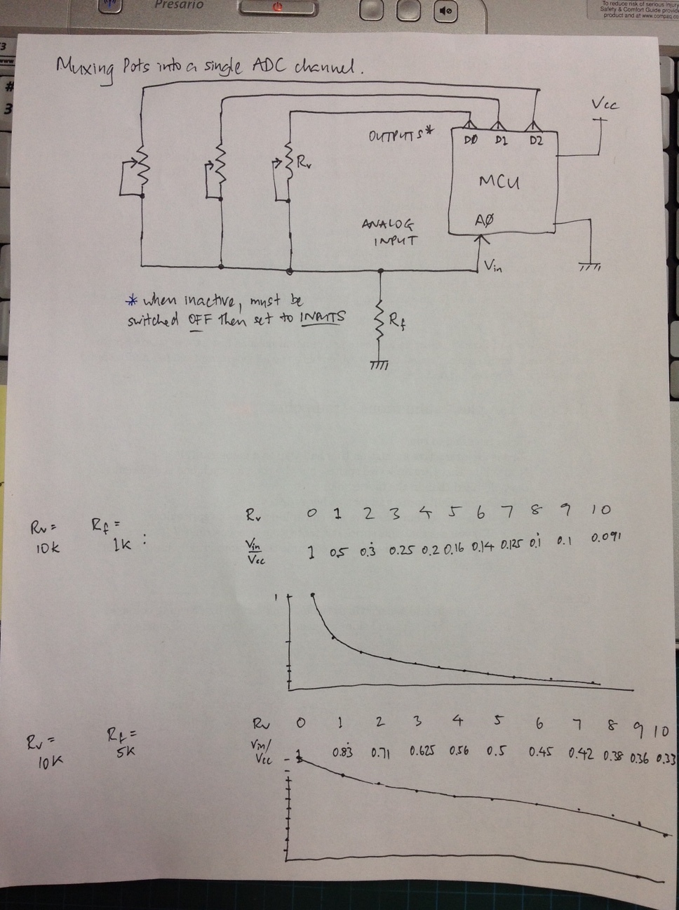
@spuug and @Shane have almost got it. The trick is to use the pots as variable resistors between a common sense line and the digital outputs that are used to select one active pot at a time. A single fixed resistor between sense and ground completes the deal. No diodes are necessary and there are no sneak paths. Two things to consider are:
The digital outputs that are not active must be tri-stated (i.e. set to inputs with pullups disabled)
The choice of fixed resistor is a tradeoff between using the full range of the ADC input and having a nice linear response to the position of the pot. If you don’t care about the linearity (e.g. if you are going to do a calibration in software) then you are better off using a smaller resistor.
I enclose a sketch including the response for two example values of fixed resistor, so you can see what I mean.