SMD Build Night - fadecandy $15 plus fees Feb 25 7pm @VHS

We’re building the fadecandy LED strip controller board at Vancouver Hack Space. We run SMD soldering build nights from time to time, this is one of them.

The centerpiece of the Fadecandy project is a controller board which can drive up to 512 LEDs (as 8 strings of 64) over USB. Many Fadecandy boards can be attached to the same computer using a USB hub or a chain of hubs. Fadecandy makes it easy to drive these LEDs from anything with USB, and it includes unique algorithms which eliminate many of the common visual glitches you see when using these LEDs.

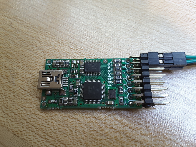
As you can see by the image above this is a fairly crowded board with some fine pitch components. You’ll need to have soldering some SMD before to attempt this.
We have some soldering irons and magnifiers at VHS, it is suggested you bring your own to ensure availability. It is also best to keep using the same tools as every tool is different.

WHEN
Thursday, 25 February 2016 from 7:00 PM to 10:00 PM (PST)

WHERE
Vancouver Hack Space - 1715 Cook Street. #104. Vancouver, BC V5Y 3J6 CA - View Map

TICKETS
https://player.vimeo.com/video/79935649

4 Likes

Woot, see you there

Booked my ticket! Looking forward to this.

1 Like

Woot! I’m also in. I tried to resist signing up for this…cause how many RGD LED controllers do you need? But this looks awesome!

I know the feeling… The blinky flashy always gets me…

I just did some reading up on the Fadecandy, because I wasn’t sure what made it special, and why I’d want to use it rather than a Teensy or something.

tl;dr Fadecandy is an LED driver board for your PC that makes the LEDs animate more smoothly, without any extra effort on your part.

Here’s what I found:

Fadecandy can be thought of as a WS2811/2812 driver board for displaying data from a PC. It doesn’t display anything on its own, and although you could certainly reprogram it with the Arduino IDE to do whatever you want, that’s not the intended use. You’re not writing your visualization algorithms in Arduino code to run on a microcontroller; instead, you write them to run on your PC (or mac, or raspberry pi) in C++, Processing, Javascript, Java, Perl, Python, etc.

What does fadecandy do, then? It receives visual frames sent over USB to be displayed, and applies automatic interpolation between frames (it interpolates pixel colours, doesn’t infer movement or anything crazy like that), high precision colour correction, and temporal dithering (flashing two adjacent colours to get the perception of an in-between colour). The combination of these features is meant to improve colour accuracy, dynamic range, and animation smoothness.

What is the hardware? It’s essentially a Teensy 3.0 (same microcontroller (MK20DX128)) plus the OctoWS2811 shield (same level converter chip (74HCT245) to output 5V signal).

Max LEDs: 64 LEDs per string (x8 = 512 total) (note that the LED wall at VHS is 8x8x3x4 = 768 LEDs)
For more LEDs, get a USB hub and more fadecandy boards.
5V power supply is required to power the LED strip; limitation of USB (might get away without one if using <10 LEDs, not sure).
Data is pushed over USB. AFAIK, there is no UART bypass or anything like that. It’s for use with a computer.

Good references and overviews:
https://github.com/scanlime/fadecandy

1 Like

Thanks Shane! We can’t build our own Teensy because the pcb and bootloader are closed afaik. I think the main reason you’d use a fadecandy is the number of leds it can drive. It’s also really nice to be able to write sequences in python etc.

When you guys are using the word LEDs in this very particular context, as in “…can drive up to 512 LEDs (as 8 strings of 64)…”, am I correct to think you are talking about manufactured assemblies of particular LEDs, with a communication path on board, or am I to assume individual LEDs?

It can drive up to 512 WS2811/12 led nodes (each of which has a R, G & B channel)…
Limited though, to 64 nodes on each of the 8 outputs…

So it cannot drive plain old LEDs, just the WS2811/12 led nodes…

Excellent answer, thanks!

When we say LED here, we’re meaning specifically WS2811/WS2812 packages, which are actually 3 LEDs (RGB) per package, plus a microcontroller (per package) that receives/relays a data signal, and PWMs its LEDs to produce a colour. Some pixels have 4 LEDs (RGB+White), but I don’t know if Fadecandy can do those. The LED wall at VHS uses WS2812s Adafruit brands them as NeoPixels. Here is what the SMD versions look like:

It’s also a 4-layer board, which I’ve heard is harder to get built for cheap.

1 Like

Pretty fancy little buggers.

Nope, 5x5 is about $28 for 10 boards at dirty pcbs, so just twice the price for 2 more layers :wink:

1 Like

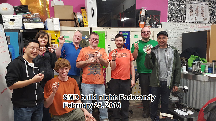
Lots of fun had by all tonight. The statistics were only moderate - we had 4 complete and 2 no shows and 3 needing more TLC.

@rsim I owe you two kits now

@Logan_Buchy I put most of a kit together but it will be easier to build if I am around. Perhaps next Friday?

1 Like

Thanks @TomKeddie for running the workshop.

For Windows users:
Unconfirmed: I think If you have firmware version 1.06 you will have two instances of fadecandy in your device manager and will need to do the following steps to getting windows drivers if they don’t automatically install. It’s supposed to install if you have Vista or later with latest updates, but might not install properly depending on your existing drivers.
http://www.libusb.org/wiki/winusb_driver_installation
(TL;DR download a generic driver and modify the “multiple interface” .inf files with the hardware codes for the two fadecandy instances)
You can generate GUIDs here: www.guidgen.com

After I did that I was able to connect my device and upload new firmware (1.07) which led to it showing up as one instance. Unfortunately it then showed up as unrecognised and I had to re-install the driver =__=. Oddly now it doesn’t report firmware version 1.07 it still says 1.06. I don’t know anymore. It works, it connects, ~yay.

Here’s some quick links to save you some googling:

Fadecandy repository:
https://github.com/scanlime/fadecandy

Fadecandy releases (includes firmware, dfu_util, server):
https://github.com/scanlime/fadecandy/releases

Instructions for using the dfu_util:
https://github.com/scanlime/fadecandy/tree/master/bin#firmware-update-tool

Adafruit Getting Started (Installing Software step w/ links):

1 Like

2 Likes

Demo of the Fade Candy
https://www.instagram.com/p/BCPcrAZA5Q7/?taken-by=funvill

1 Like

Thanks for the links and demo. How do i flash the firmware for the first time?

Doug, thanks for all the details. Sorry about the v106/v107 thing, it’s hard to cover all the bases in a workshop like this.

Yah, the king of leds keeps his crown.

Janet you need dfu-util (http://dfu-util.sourceforge.net/)

You can get the firmware from https://github.com/scanlime/fadecandy/tree/master/bin

You need to upload the .dfu file, there are instructions on that page.

1 Like

That’s okay, the documentation on this is pretty good. Only the drivers was a bit of a gong show and I’m sure we can just blame it all on Windows. I don’t really understand why the device shows up as two instances though. Also, the hardware ID changed when I updated the firmware which is why the driver had to be reinstalled. It only changed the ID of one of the instances though (went from PID_607A to PID_6082)

Also, did you find out where you got 1.08 firmware? I took a quick look and saw some areas of the server dev that referenced new development for 1.08 but I haven’t yet found the firmware itself.