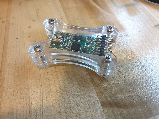
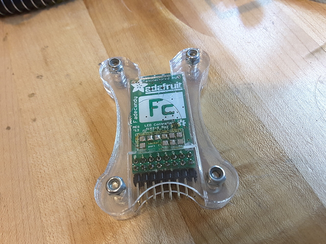
Should my USB port at least see some unknown device prior to uploading
firmware? I’m trying to figure out if the board is soldered correctly.
Do we not have to use OpenOCD first, or can we do everything with dfu-util? I spent a few hours this morning trying to figure out OpenOCD + Bus Pirate + Fadecandy, but having no experience with any of these, I think my time would be better spent waiting for the next time you come in. ![]()
Yes. The blank chip does nothing without the bootloader which is programmed over JTAG. In hindsight I should have lent you my programmer. I’ll see if I can get it (and the adaptor cable) to VHS before I’m in next (Friday next week).
You and @jon were the only ones not to get the bootloader programmed, the symptoms were similar so they might be recoverable in the same way.
https://github.com/scanlime/fadecandy/tree/master/bootloader
Ok thanks, no worries. My programming header was hastily soldered on (and then fell off) so that may have been my problem. Everything else looks fine, so I’m going to leave it for now until I can actually test if it’s fixed.
BTW, what component(s) on the board create the 3.3v from USB 5v if there is no voltage regulator? I do get both voltages on my board, i’m just curious.
Assuming the schematic here is right:
https://github.com/scanlime/fadecandy/blob/master/pcb/fc64x8/fc64x8-schematic.pdf
There are actually two regulators on-board. The 3.3v you’re seeing is fed
from the MK20DX128, which is a Cortex M4 microcontroller with an on-board
regulator, page 45 on this PDF right here:
http://cache.freescale.com/files/32bit/doc/data_sheet/K20P48M50SF0.pdf
The outputs are fed from a completely different 3.3V source, the AAT3110,
which is a monolithic switch-mode converter.
I don’t know why she used two different regulators for sure, but I’d assume
the switching load of turning on and off a whole bunch of LEDs quickly
would cause problems with the microcontroller operation.
Cool, thanks! I was wondering if microcontrollers ever had onboard regulators. The external regulator is apparently a 5v-5v regulator, and a part that’s very hard to find, so we were just instructed to short two pins together.
Tweet from the FadeCandy creator
Whoa, just found out about this. SMD build nights at @VHS, and DIY fadecandy happened! pic.twitter.com/jQhSFPYiIb
— Micah Scott (@scanlime) March 3, 2016
nice…
i got mine working but now i need way more leds to make a wall display…
@rsim @Logan_Buchy Your kits are in the dropbox, thanks to @Shane.
You’ll need to make a time with me to program the bootloader.
I noticed someone’s FTDI board left on the table from tonight, near where @SteveRoy was working. I put it in the dropbox, on the right wall.

