Phase Control Modulator using solid state relay

Hi everyone! I am having a little difficulty building a pulse width modulator to control a 1500 watt hot water heating element. Yes I am making beer… I’m hoping to control a solid state relay with a simple circuit board and a potentiometer. I have everything made including the custom case and I have mounted the relay to a fan cooled heat sink. I attached a potentiometer to the signal end of the relay but nothing except the fan works, probably needs power I’m assuming.

Any help with this would be greatly appreciated, I have a large CNC that I would make available for your project provided it was reasonable in the time required to cut. I also have an optical (structured light/ laser) 3d scanner.

I’m willing to trade help for help.


2 Likes
  1. That is a really nice looking enclosure!
  2. That black wire looks too small for the ~12A a 1500W element will draw. It should be 18AWG or larger.
  3. Are the potentiometer and the red wires rated for at least 120VAC?
  4. How are you getting power into this box? I only see outlets.
  5. Can you post a schematic or wiring diagram? It’s hard to follow wires in a photo.

  1. Thanks djqq
  2. Small black wires are for the cooling fan, I thought they were too small but the fan works fine and they came with it.
  3. Potentiometer is hooked up to the low voltage side of the SSR, 470k ohms, 1/4 watt. I think its a 5 volt circuit?
  4. Power is supplied through a heavy duty power cord for tool repair from home depot, case is grounded.
  5. Please excuse my rough schematic, I’m fairly bone headed about electronics and electrical in general. I went from the drawing supplied to me by the guy at Lee’s Electronics. I purchased a PWM from ebay that was rated for what I need but the thing burned out after a minute of use. I took this un it in and asked if I could build a more robust unit and they provided me with the components to make this with no guarantee it would work. I think the problem may be that the SSR trigger side requires some current, there is just a potentiometer hooked up to it currently.

The more common type of SSR takes DC voltage on the input pins, ideal for driving it from a microcontroller. The one you have is designed to connect directly to a variable resistor, which is kinda neat! I’ve never seen those before. Here’s the datasheet for the SSR-40 VA you have.

It looks like your wiring setup is fine. But do you know the range of your potentiometer? The datasheet says it should be 250kΩ when switching a 110V load. If there is no marking on your potentiometer you can test it with a multimeter.

Also note that SSRs require AC voltage to work. You can’t just test DC continuity like you can with a mechanical relay. This is doubly true for this particular model which apparently uses the AC voltage to power the switching circuit as well.

I’m happy to help further if you want to bring the unit into VHS sometime. I’ve got a flexible schedule and will be down there quite a bit this week. I recently built a very large water bath pasteurizer using hot water heater elements and a couple of SSRs similar to yours. Also I’d love to see this enclosure up close — it looks incredible!

Super interesting, I didn’t know that these relays came in PWM! I have a few that are just on/off zero crossing and take straight DC.

So, one interesting quirk of mine are that they NEED some load across the AC to work. I’m guessing yours are the same, and this is why you’re only seeing the fan working.

I’d suggest just finding a light bulb and plugging it in, to see if that gets it to wake up. This will then let you test with a scope/multimeter (you need a good multimeter to test this, needs to be “true RMS”), or just look at the brightness of the bulb. You’ll get best results using an old, incandescent bulb. Not much more stable than a resistance heater.

Also, luke’s question about the potentiometer is important.Needs to be matched. Luckily, you can just add resistors in series/parallel to make the one you have work if it isn’t the right one!

If you can bring it to VHS, I’d love to help you get it going, and snap a picture or two of the scope when measuring the output. Always nice to see how things actually do their modulation.

Oh, and amazing case!

1 Like

Thanks Luke, it turns out that my system works perfectly, I had just fried the potentiometer when soldering it. Bone head strikes again. I went to Lee’s and they had a multimeter and we figured out what was wrong. I think this is a great way to get the function of a PWM in a simple unit.

I will be coming to the hack space to meet you all soon as I have a MILLION projects to figure out.

1 Like

Turns out the relay has power across the input terminals, just hook up a potentiometer and go, so cool. I just bought another one when I was at Lee’s.

Thanks for the complement on my case, I spent the whole weekend working on that and was worried my system didn’t work and I would have to discard it.

That’s a gorgeous enclosure!

FYI you might be interested to know that eBay has dirt cheap PID temperature controller packages that include an SSR, thermocouple, and controller (with display) if you are looking to control/maintain temperatures more precisely. (i.e. http://www.ebay.com/itm/AC110-240V-LED-PID-Temperature-Controller-25A-SSR-K-thermocouple-Sensor-/172112790438?hash=item2812b8c3a6:g:gfEAAOSwe7BWzXn1)

1 Like

Glad you got it sorted out!

As @Rob_MacKenzie pointed out, SSRs do have a minimum load requirement to work properly. Could be as much as 30W.

Another important thing to know about SSRs is that they have a few mA of leakage current. That is, they are never really “off!” It’s probably not enough current to hurt you but it could give you a nasty zap. Make sure you disconnect power before you touch the terminals.

1 Like

Wow, that’s cheap! I basically have this system now but I paid more than four times the price for it. Also the thermocouple in that system seems better suited for some of my needs. Thanks for the info Ryan.

Do you happen to know how to program PID systems? My system tends to overshoot a lot and this will destroy enzymes really quickly. I can’t seem to find any good info on how to program these units online, but then again I am a bit of a bonehead…

Thanks for that as well Dave, I NEVER work on anything that is plugged in. Do these units ever hold a charge after being unplugged? I am noticing that on this unit that the potentiometer is useless below half “volume” and that the graduations are extremely fine. Is there some way to rectify this? Or what I mean is to make the potentiometer more equally rheostatic along its entire range?

I needed this PWM system to control the kettle elements on boil, the PID system is for holding the temperature of the mash tun for grain starch to sugar conversion, this is a slower more steady process. PID is not as suitable for element dimming.

https://www.mpja.com/download/rex-c100.pdf is supposedly the manual for the unit, but I think the ones sold on eBay (and probably the one you have) are cheap Chinese copies that might not follow the same control scheme/parameters.

I think the unit should have an autotune feature (see the ATU/ auto-tuning parameter on page two of the pdf linked above) to improve stability/performance (I think the standard procedure is to bring the system up to around the temperature setpoint then enable autotune). If that doesn’t work out, there are resources online to help you tune the parameters manually, but it’s a pretty involved process (it seems like there’s a fair amount of art to it) and I don’t have too much experience with it.

Hope that helps! Also, the screw type thermocouples are literally a dollar on eBay if you don’t need another controller/SSR or want spares.

If I didn’t work on things while live, how would I get my hair to stand up like I want?

Adjusting the pot is easy, you’d just add in resistors like I said above.
Measure your pot’s resistance fully one side of rotation, fully the other, and at 1/3, 1/2, 2/3 positions. This will tell us the taper of the pot.

Post the values here, then you can just put a resistor in parallel with the pot, and it’ll change the taper curve of the pot.

Reading the data sheet, I’m a bit confused about what potentiometer values relate to what duty cycle for the PWM… If you have time, drop by the space, and I can hook it all up and measure it with you. This would be super fast, as we can see exactly what’s happening and adjust accordingly.

1 Like

Here is what I predict will happen, if your pot is currently going up to 500 ohms, and the PWM starts at 250:
The black line shows your existing pot(though is a linear pot, yours may not be)
The other lines are with resistors in parallel, giving a better curve for you,

If this is in actuality what’s happening, you’d want the purple curve, and a 500 ohm resistor.

*Edit:
Oops, those should all be kilo-ohm, not ohm. But I redid it, and it’s the same curves, you just want a 500k resistor.

I haven’t done PID stuff much yet, I did research it a bit though for an upcoming project. Have you considered using both PWM and a PID circuit for what you’re doing?

@lukecyca is a great resource on this, he’s built similar stuff. He may be able to further suggest ways of dimming the element.

I have a Lionpower CD 100E the manual is in Chinese, I was lucky to get it wired up correctly. I purchased it from Lee’s for around $45 I think. I have a K type thermocouple hooked up to it.
Thank you for the link, I shall look into it shortly. I suppose I could fill my vessel with water and test it once it is at temperature. When you add the grains to the system it lowers the temperature and then changes the specific heat capacity of the now solution. I think the grain insulates as well as impeding flow by thermodynamic cycling, which compounds the error. I am sourcing a food grade hot water pump to try to more evenly distribute the liquid.

Thanks Rob, I have a 500k potentiometer hooked up to the SSR now.
So cool man, I am looking forward to meeting you. I will try to come in next week and bring the unit with me. When are you planning on being there?

I’ve done a bunch of experimenting with high-current SSRs over the last couple years, controlled by microcontrollers as well as cheap “PID controllers”. Here’s a bit of an overview of my experiences.

Firstly, this document is a great overview of the quirks and limitations of using SSRs.

PWM

Usually when people refer to PWM, it’s for high-frequency DC switching, such as dimming LEDs from an Arduino. A Solid-state relay can take a PWM signal and sort of apply it to AC, but the results won’t be very good because most SSRs only trigger on a zero-crossing of the AC waveform. If the PWM frequency is quite fast (as it usually is) then the results will be quite unpredictable.

A better way to “dim” AC power is to use phase control. This is a similar principal to regular DC PWM, but synchronizes the switching to the AC frequency for more predictable and linear results. Essentially it just hacks off part of the AC waveform to get a lower average power.

http://ecmweb.com/site-files/ecmweb.com/files/uploads/2015/01/Leading-Edge.jpg

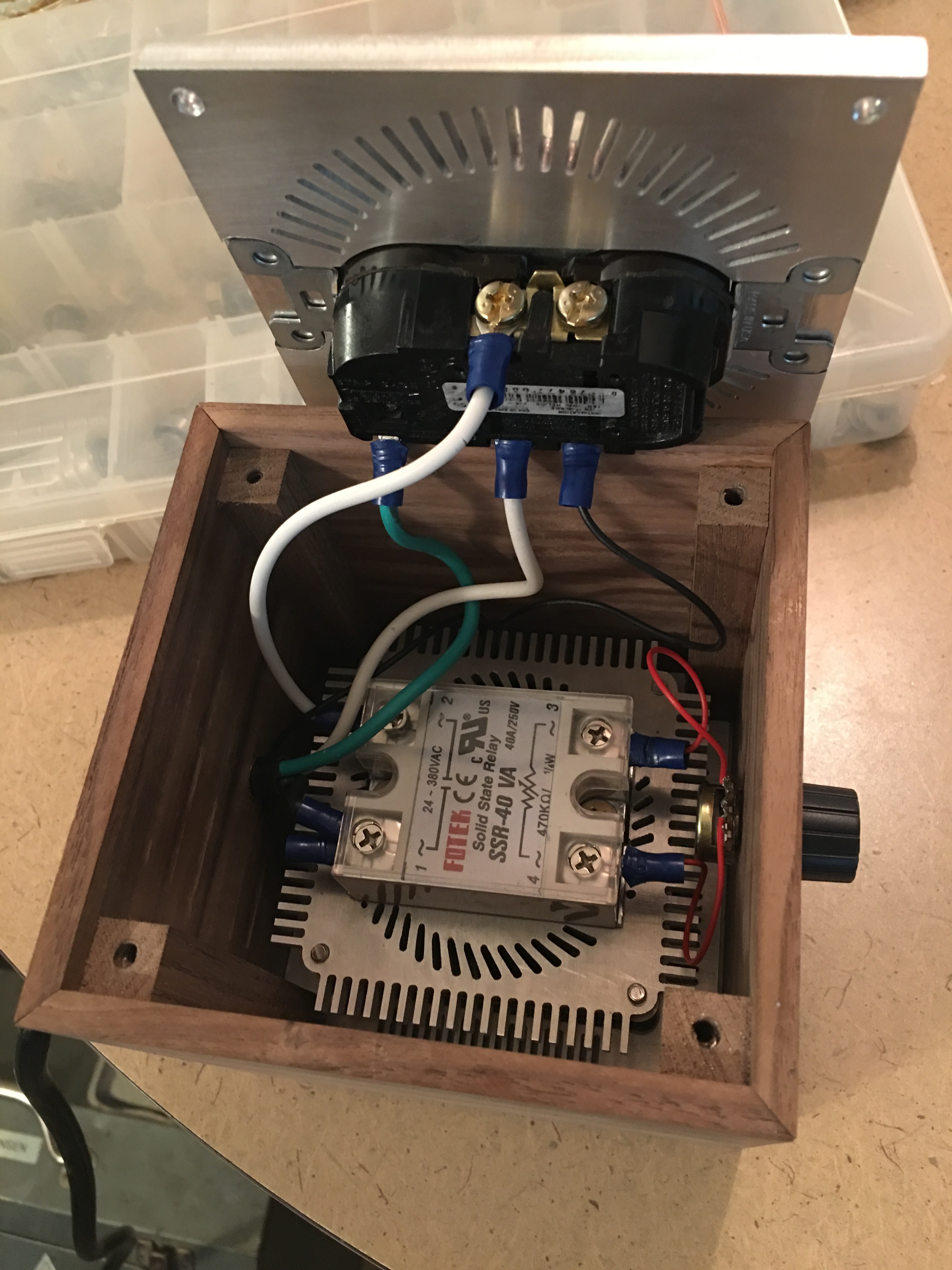
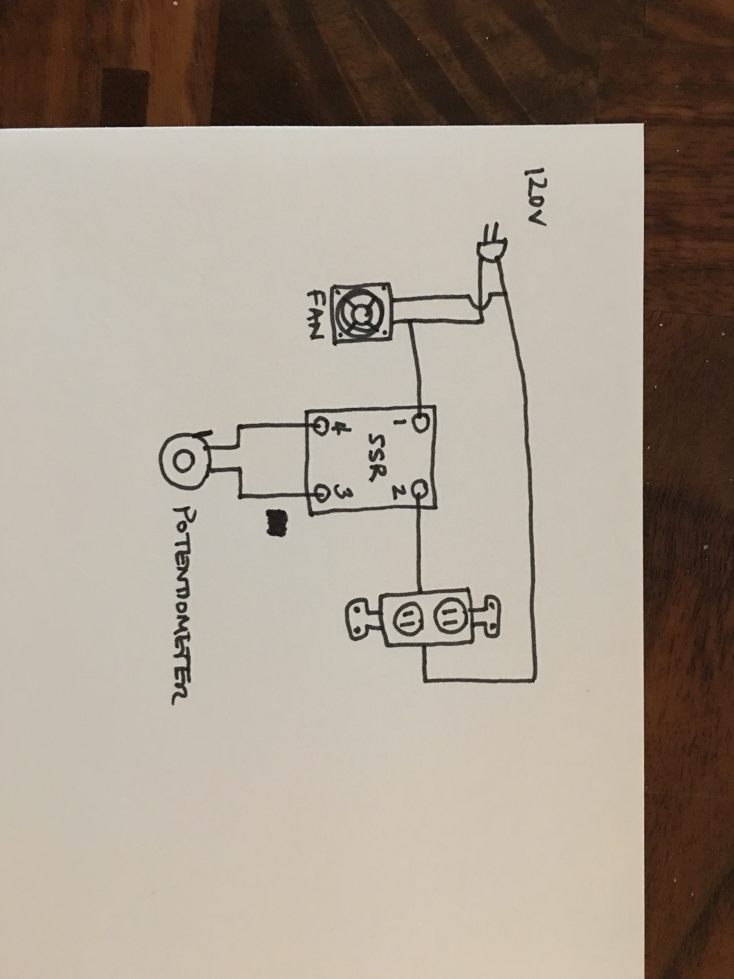
From the datasheet for your SSR-40 VA4, it appears it does indeed do phase control switching based on the resistance of the attached potentiometer. So that’s good.

PID

http://sion.rs/image/cache/data/REX-C100%20800x800-500x500.jpg

PID is just a general control algorithm and can be applied to many different things. In the context of heating a tank of liquid, a “PID Controller” usually refers to a device like the REX C-100 above. You connect a thermocouple and give it a set point temperature. It performs a PID algorithm and pulses a DC current at an appropriate duty cycle so that you can drive a regular zero-crossing SSR to switch a big AC heating element. Crucially, it operates at very low frequency (several seconds), so the SSR’s zero-crossing switching characteristic doesn’t really matter.

In the end, I guess it is still doing PWM, but at a frequency that is much much lower than the 60Hz AC waveform.

Since you’re heating a large thermal mass, you can afford to have such a slow switching frequency. Whereas if you were dimming LEDs, you’d need a very high switching frequency in order for the human eye to perceive it as a dim light.

BTW, I have a spare REX C100 that I’m happy to part with if anyone has an immediate use for it.

1 Like