Very informative, thanks for that reference document. I wonder if the addition of a resistor in the signal or control circuit will cause premature failure of the SSR unit? Do Arduino boards cause failure unless precautions are take? Also I should install a fuse circuit since they can explode!
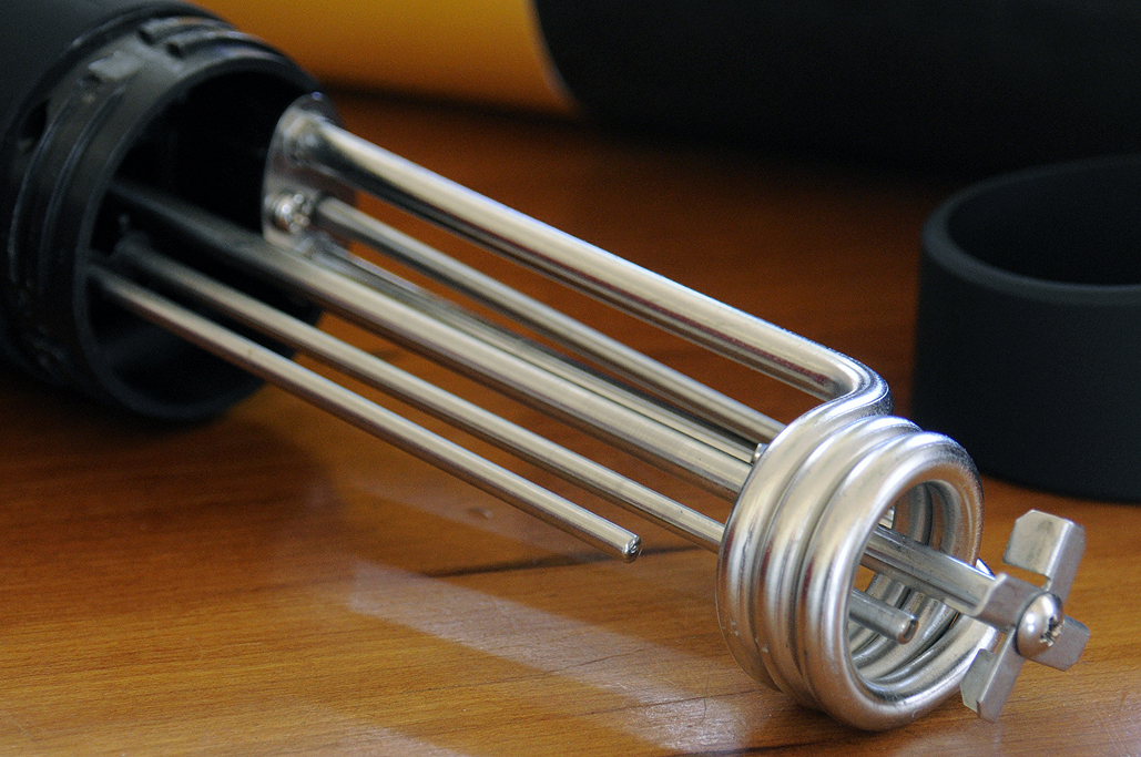
That heater impeller looks great! I do think that a pump with redistribution will perform better but perhaps the two used in conjunction would be best…hmmmmm.
Thanks for the auto tune information, I assume that’s to be used once the system is at tempurature.
The manual doesn’t specifically instruct you to, but based on what I’ve read it seems to be standard/best practice.
Without knowing what you’ve already tried (and at the risk of stating the obvious) it might also be helpful to play around with placement of the thermocouple. For example, it may be better to actually immerse the sensor and place it closer to the heat source to reduce lag and overshooting.
yep, I did that. I have the heater element and the thermocouple inside of a copper cage in the center of the mash tun. The grains are in solution around the outer edge.I placed the thermocouple on the cage edge to avoid it being too close to the element. I’m going to use the auto tune function once the pump is in place and hopefully that will be sufficient to accurately regulate the mashing procedure.
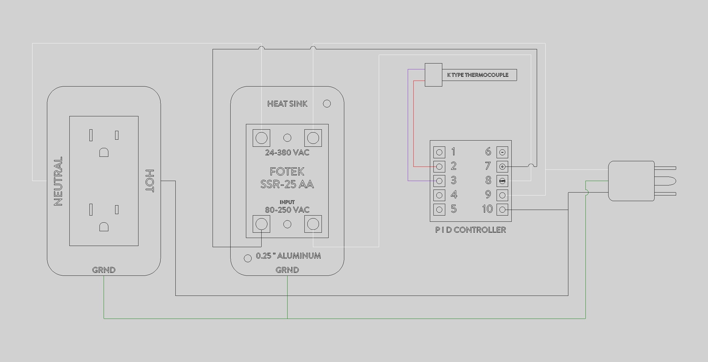
Here is my circuit diagram for the PID control unit, I have a few questions based on the information you have provided concerning SSRs.
Is there some possibility that the input circuit from the SSR could back feed voltage into the PID controller at pins 7 and 8, damaging it?
Do I have these pins wired correctly, or does it not really matter since this is AC?
Do you think that my heat sink is sufficient for cooling the SSR, I will fabricate it myself with cooling fins engraved on the back side. Its designed to be the same size and shape as the outlet box behind it to make the enclosure as compact as possible.
It depends on the exact model of PID controller. If it is giving 120VAC output on pins 7&8, then it appears that got this wired mostly correctly.
You should be switching the HOT wire to the receptacle, not the neutral. Either will work, but as it is you’ve got a voltage potential “always on” to whatever’s plugged in, and it’s just itching to get to ground.
Depends entirely on how many watts you’re planning to pull out of the receptacle. For these cheap FOTEK SSRs, I always “de-rate” them by at least 50%, and use a heat sink, and maybe a small fan too. If you stay under 10 amps (1200 watts), you’ll probably be ok with just a heat sink, but keep an eye on it.
Since your PID controller probably isn’t fused, you could put a small one on it’s hot lead.
You could also put a fuse or breaker on the entire thing, but you can probably rely on the upstream circuit breaker for that, as long as all the internal wiring and components are rated up to its current rating.
Switch the hot wire, not the neutral wire.
Some safety precautions:
Run this whole apparatus on a GFCI breaker or receptacle. That will offer you some protection in case it gets wet, wires come loose, etc. This is important when using it for brewing.
Have a way to know whether the SSR is actually on or not. Don’t just rely on the PID controller or even the little red light on the SSR. Plug in a small nightlight into the receptacle, for example. SSRs can fail in the “on” position.
Don’t run this unattended
Disclaimer: I’m not an electrician, I just play one on the Internet. Know the risks and be careful.
You can have it in exchange for a demo of your CNC sometime.
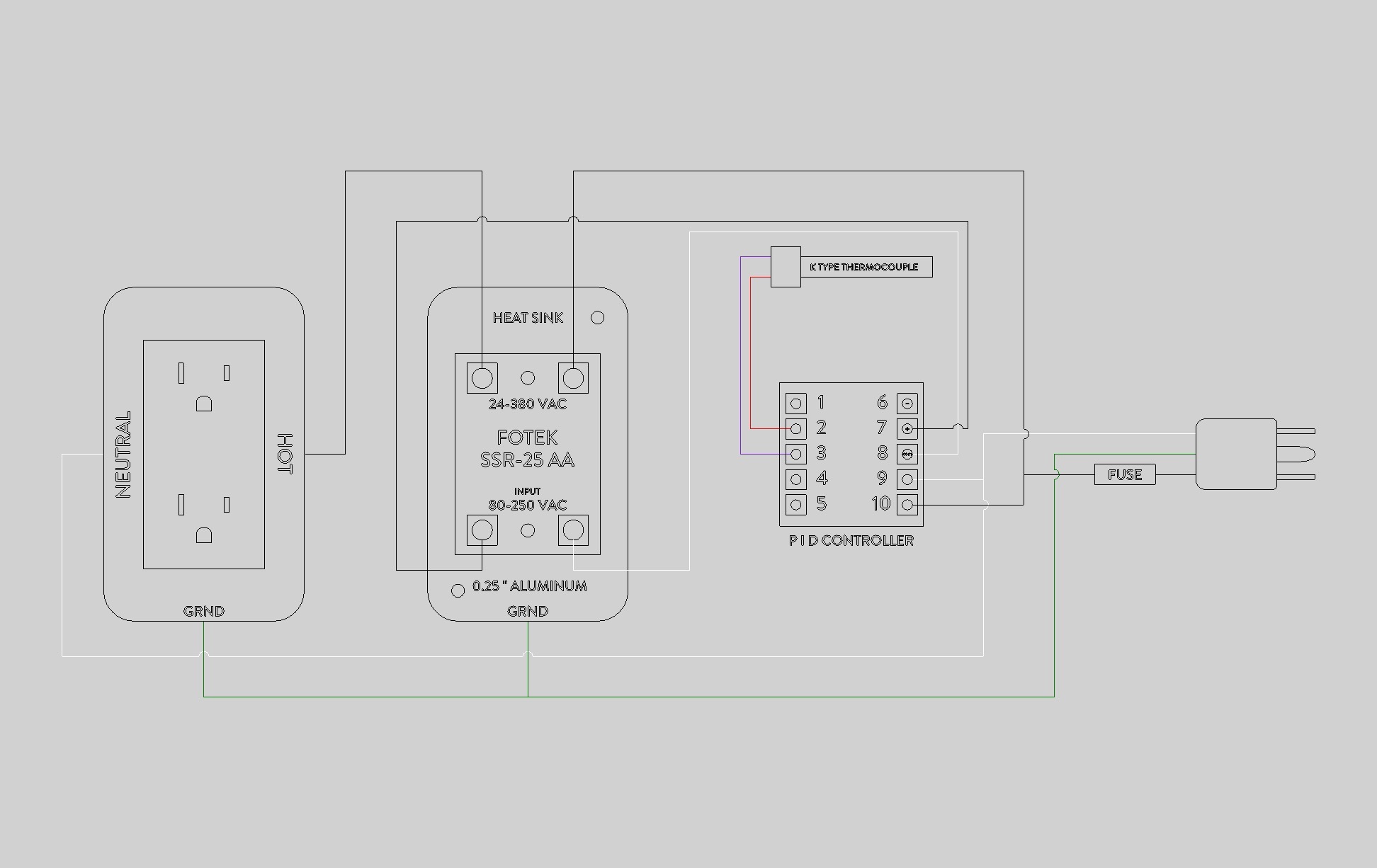
Thanks for the advice Luke, I implemented the suggestions you provided. It was indeed dumb to switch the white wire, I should have known better. I had this system running on a board using a mechanical relay and using a power adapter to change the voltage to switch the relay. It was ugly, clunky, and loud. I purchased this relay in order to replace the power adapter and mechanical relay.
Is the position of my fuse going to protect the system from overload?
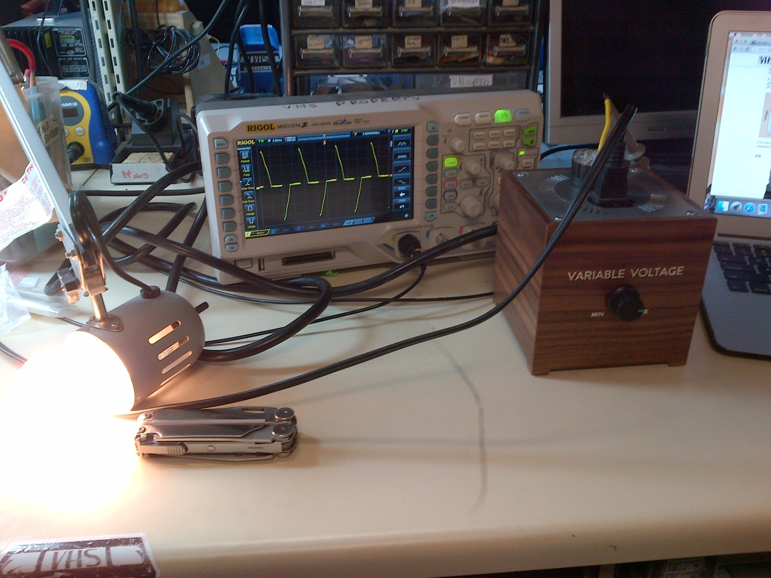
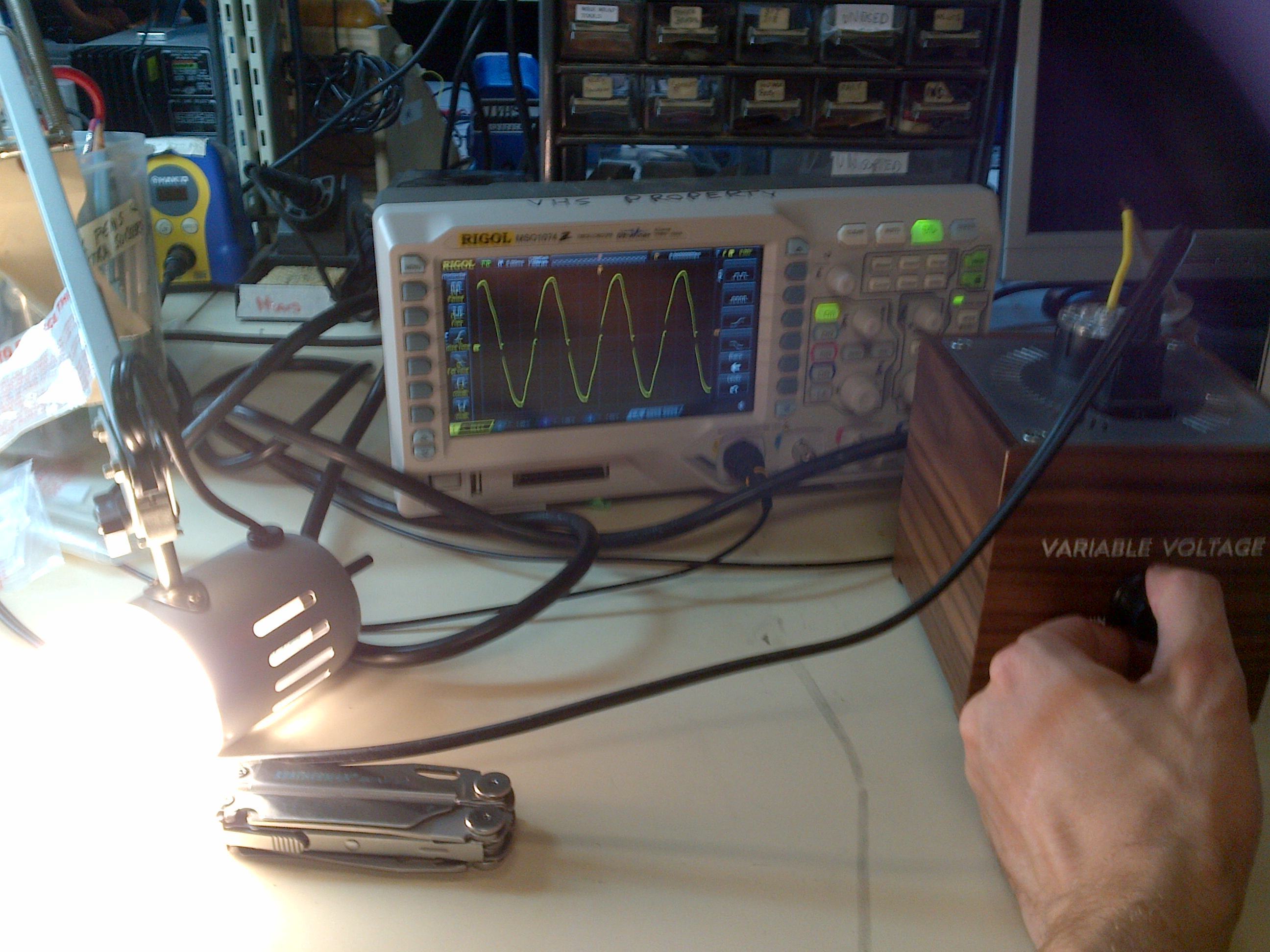
The heat sink will not be cooled by fan, only by ambient airflow through vents in the case. I’m hoping that this will be sufficient since the SSR will likely only be triggered to switch on for a duty cycle of 50%. in other words it would be turning a 1500 watt heating element on for 30 seconds and then it would rest for 30, or whatever the PID program would designate after auto tuning. Its not going to be functioning like the PWM I made. I ran the PWM for 8 hours at almost complete dimming and noticed the unit was only mildly warm, it has a fan and a heat sink that is approximately the same size.
Concerning the trade for the PID, what would you like to make? My CNC is not as complex to operate as the one at the hackspace. It’s control is software based. I have a shopbot PRT Alpha which is upgraded to PRS Alpha in electronics and drive system. I am happy to help you make something, just let me know the part or send me the file and I will advise.
If the SSR failed in the on position the PID temperature reading would show it climbing, the result would be a boiling mash in the worst case scenario. Maybe at a later date I could install a failure warning light or fuse shut off circuit.
The way you have it, your whole load is behind that small fuse.
I’d run two different plugs, one for the load side, one for the controller.
You also have your connection on the PID wrong, the black (hot) should be bridged over to NO (Normally open)
The Common should be wired to one side of the input for the relay, and the return should be on the same connection as neutral (pin 9)


