One of the best features (other than the cool guys that run it) of dirtypcbs is that they choose to let you explore the capabilities of the board house without vetting what you submit. Some times that’s garbage in garbage out (I’ve had to de-panelise boards with a metal shear). Some times the result is golden.
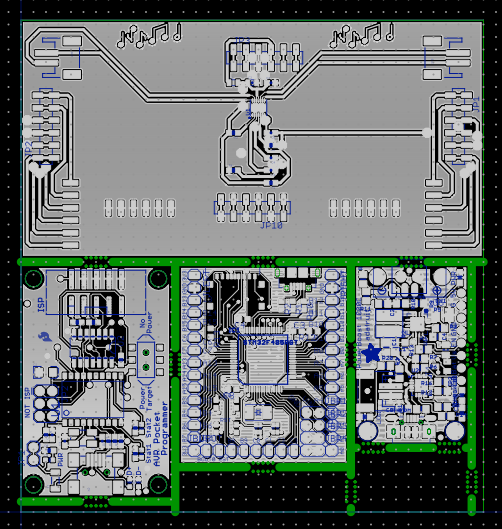
The goal is to get as many PCBs as possible for your money. Here I managed to fit 3 open hardware projects plus my project into a 10cm x 10cm panel - you get up to 12 of each panel (min 8) so that’s up to 48 PCBs for $US21 shipped!
I’ve tried lots of methods, recently I’ve found they won’t add mouse bites for you so you have to add them yourselves.
http://www.pcbuniverse.com/articles/Mousebites.png
It seems like lot of work, the file formats are ancient so they’re somewhat ambiguous. Here is what I did. None of this is essential, this is the result of hours of work so consider following it.
- Hack eagle to generate drill files with leading zeroes. ie. edit eagle.def to change the EXCELLON_26 drill line to look like
Drill = “X%08.0fY%08.0f\n” ; (x, y)
-
Install aperture scripting from mercurial (Jerome fixed a bug for me so get the latest) http://piratery.net/aperture-scripting/index.html
-
Set the LUA_PATH env var appropriately.
LUA_PATH=‘/Users/tom/hg/hg.piratery.net/aperture-scripting/?.lua;/Users/tom/hg/hg.piratery.net/path/?.lua’
-
Write crappy script to join all the pieces of pcb together. The library will only join panels of the same size so you need to add little filler pcbs to pad them out. Yes I have too many fillers, I’m done with this for now!
panel.zip (1.2 KB) -
Here we have my board, sparkfun pocket avr programmer, micropython pyboard and Adafruit Powerboost 1000C.