This is the latest update on the refurbishment. I originally tried to copy this directly from my e-mail. I’m not the one refurbishing this, it’s one of our members (Mike) who’s got it in process. I was hoping to attach the text with pictures in tact but I’ll have to upload them separately. The latest update is below:
You had asked about some pictures. Since I’m back into it up to my elbows, I thought I’d take a few. Photos without explanation isn’t as interesting so I’ll provide some extra background.
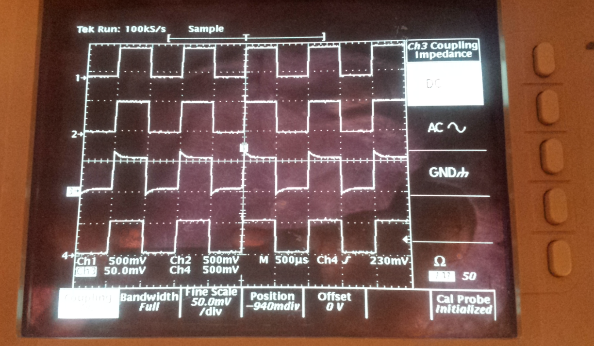
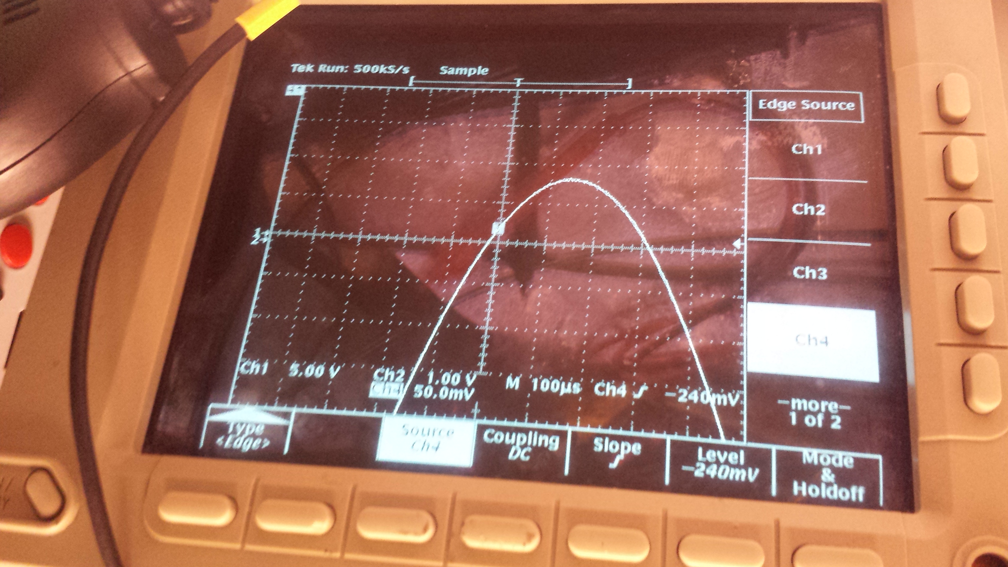
An early “victory-run” as it were after I fixed the vertical shift register & offset sample & hold: (didn’t bother to compensate the probes; it wasn’t important)
The attached photo ending in 4723 showed the waveform still with a massive offset due to a failed op amp. It prevented seeing the rest of the waveform at all. The waveform position was adjusted to the limit to be able to see anything at all…
I broke out the logic analyzer to try to see what the CPUs were saying to each other but they seem to speak in an extremely brief, proprietary code; not English communication. Had hoped to get error information but got nothing useful there.
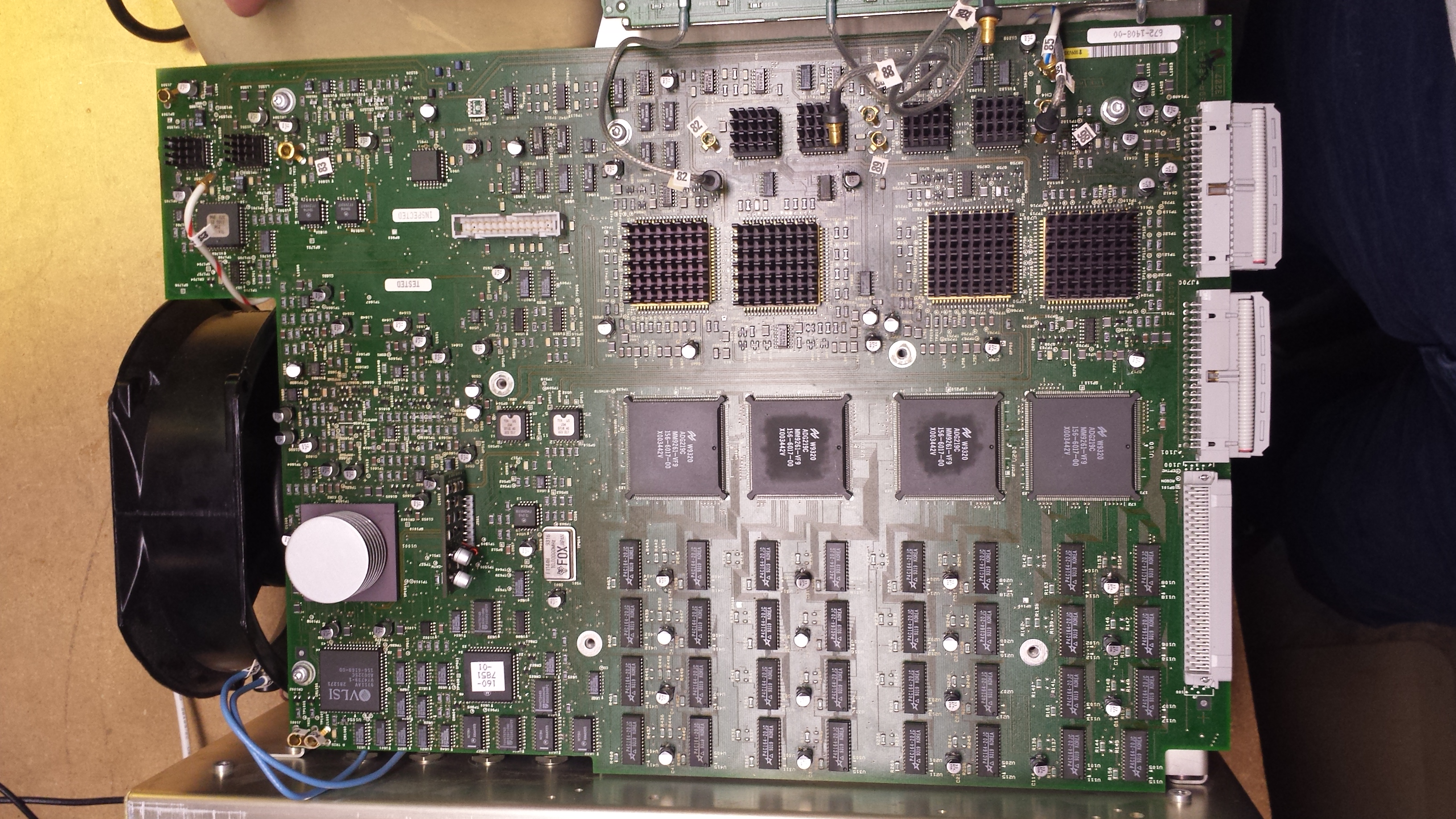
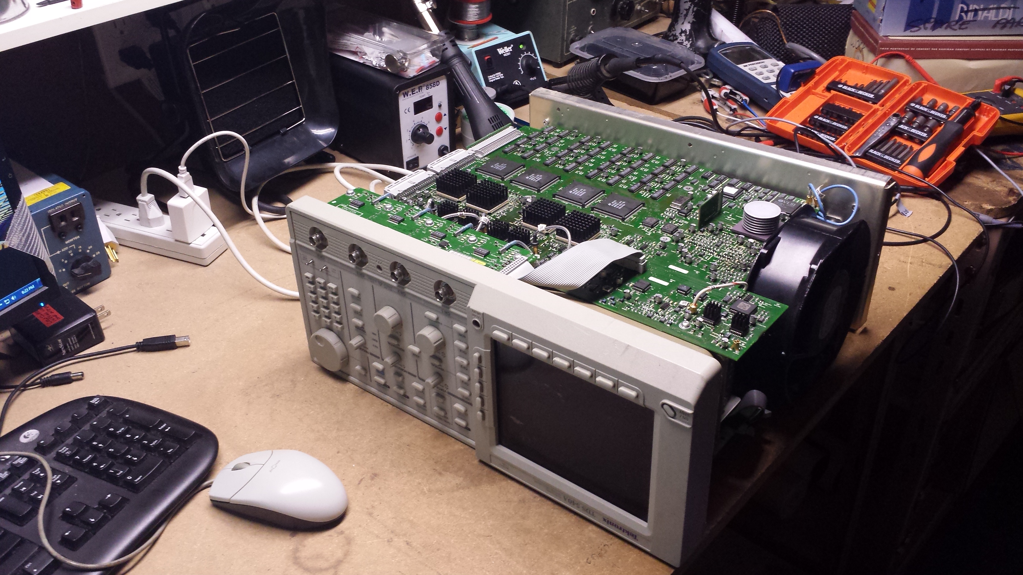
In the photo 4243, you have the acquisition board. The signal comes into the 4 preamps at the top, through the ADCs below, and into the demux below that and the acquisition memory below that. The “CD stack” CPU is the triggering & control system. From what I have seen, the big chips all seem to either have “house numbers” on them or are fully custom chips.
From what I’ve seen, they’re over-clocking the 20ns RAM by a little bit and sharing the memory 8 ways so they can use their combined data handling rate to meet their requirements of 500 MSa/s.
They’re also sharing the demultiplexers probably for the same reason.
They have designed in much self-testing including “signal path compensation” automatic procedures.
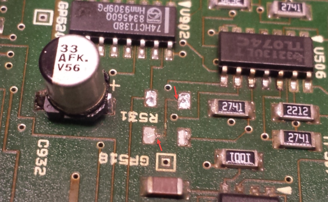
The capacitor at the left leaked its electrolyte under R531 and its companion. Over time, it ate away the traces at the two red arrows. This particular problem caused a voltage divider to not work properly and be off by 42% when clearly it was intended to be especially accurate. Fixed.
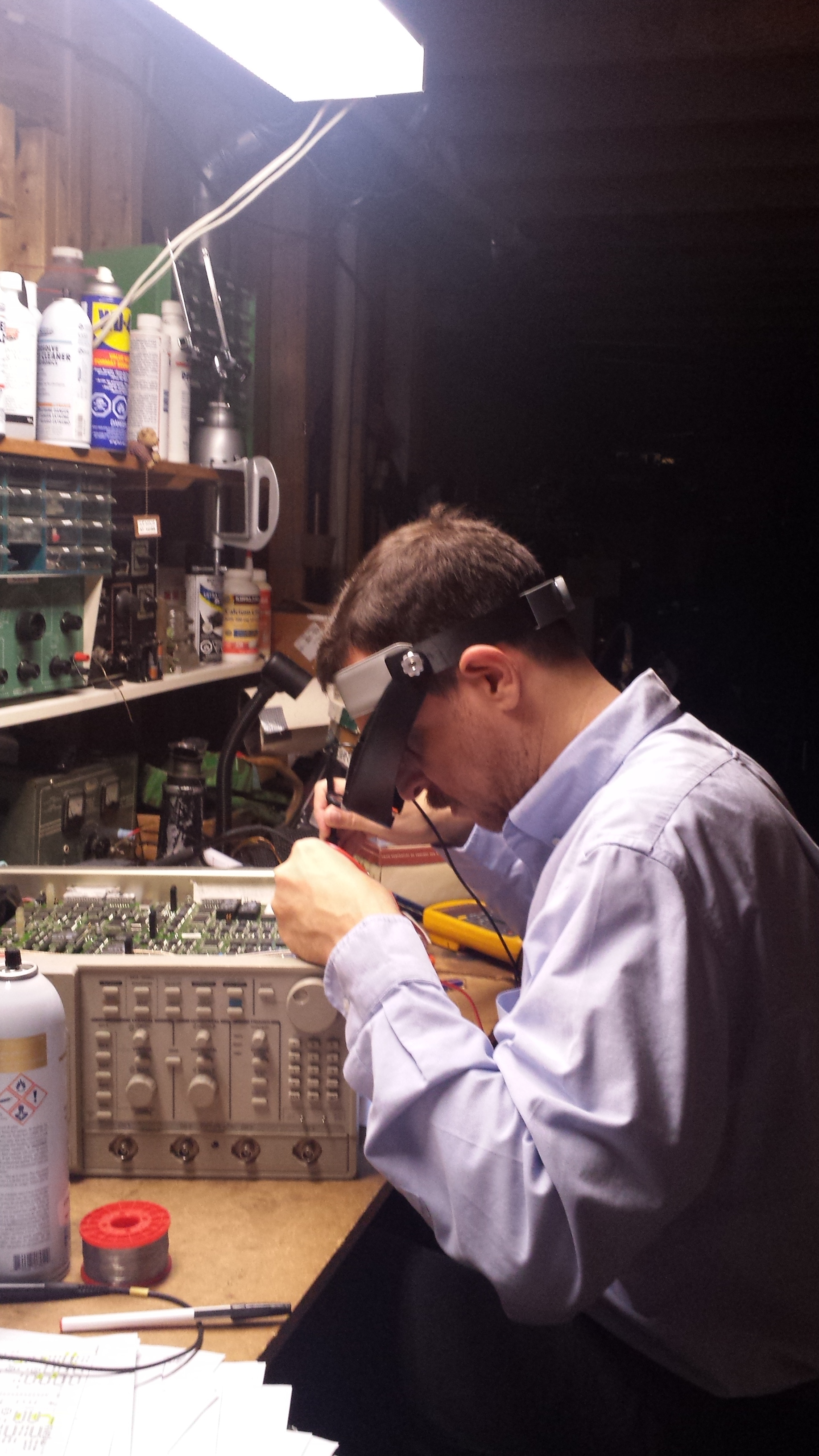
The capacitor soldering isn’t pretty; it’s really hard to solder a tab that protrudes about 0.4 mm and is surrounded by plastic. And you need to do about 100 of them in a reasonable amount of time. And you don’t want to overheat things. And you don’t have a micro soldering iron or a microscope. My iron’s tip is the smallest that will fit the iron…it’s pretty good but maybe there’s something even better out there.
The board looks “grungy” but every cm2 has been thoroughly scrubbed with suitable cleaner several times and it still looks this way. This fact is quite unsatisfying but what matters most is that it works…and continues to work. The intention has been to scrub & wash away the electrolyte so it can’t continue to create new problems. Only time will tell us the successfulness of that cleaning effort. Typically people submerge the board in water with dish soap but I’m not prepared to do that since I don’t have a drying oven nor the courage/experience for that at the moment.
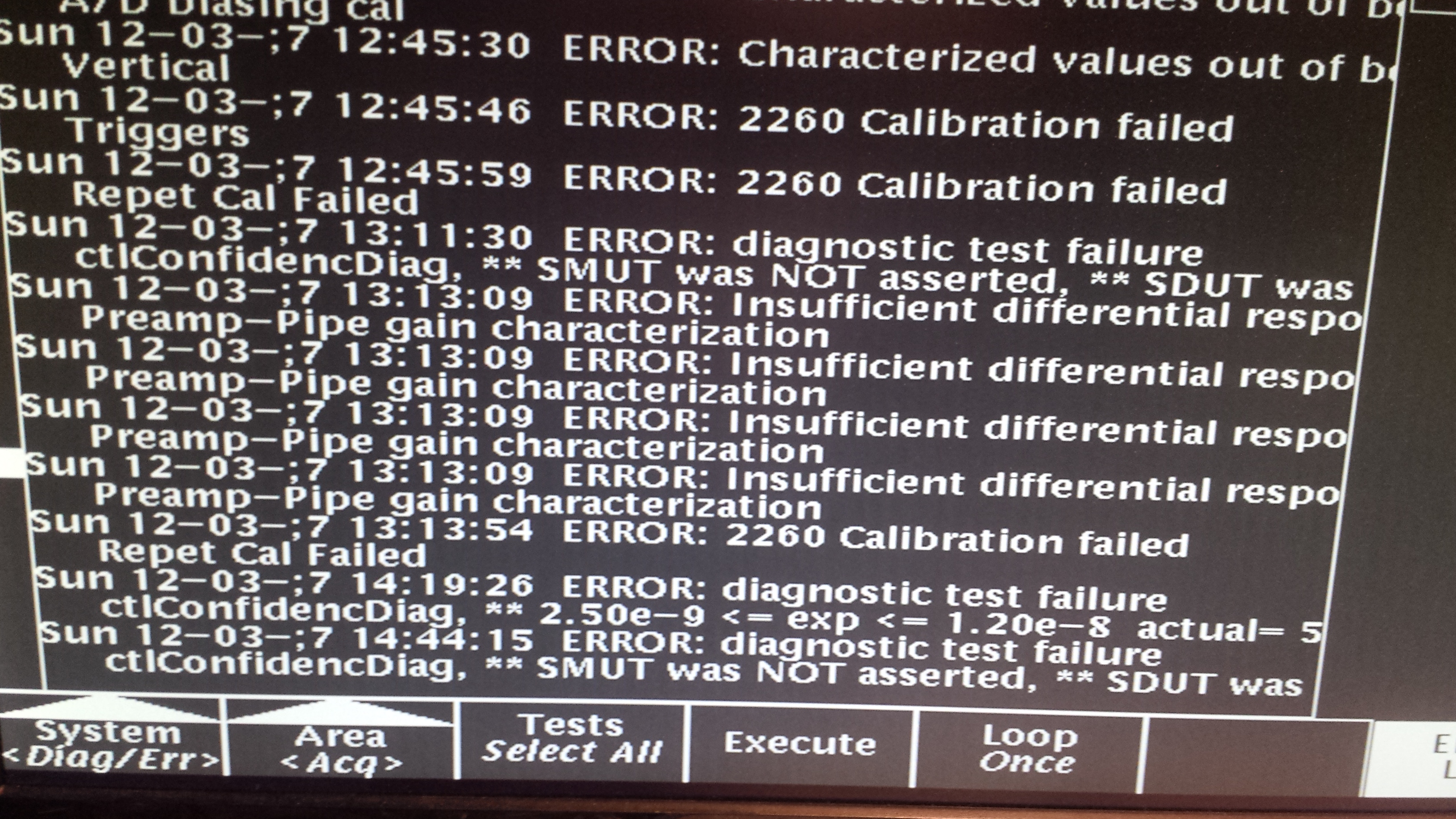
I found the above gem during a “tour” around all the circuits on the acquisition board during which time I reviewed the operation of each circuit:
· Power supplies present & healthy
· Voltage references working correctly
· Op amp inputs & outputs sensible?
· Test point values sensible & in stated ranges (if provided)
This brought out several interesting problems:
· An oscillating adjustable voltage reference in the trigger system (oops, no thank you…)
· A failed op amp intended to act as a constant current source; it was doing nothing of the sort
· A failed voltage divider (above)
· An incorrectly biased circuit in the triggering system (another dissolved trace)
The triggering system area of the board has been the most badly affected area of the instrument.
It’ll be quite interesting to see what happens with the remaining errors when these problems are fixed. I wouldn’t be surprised at all if the “ctl” errors go away. At least there’ll be fewer reasons for it to not work correctly. The things I found there would certainly be problematic.
With a GPIB interface in hand, the acquisition memory errors should be easier to solve since then I’ll know what the error actually is.
Maybe I can kill off the remaining errors by Saturday…that’d be nice but it’ll probably be a stretch since I’ll need to make & learn how to use a GPIB interface.
Again, it worked surprisingly well even with all those latent problems; there’s no concern for Saturday.
You can do with the photos or this text as you wish.
Ugh, in all the excitement, I forgot to check the compatibility of the memory with the programmer. Tomorrow probably…if I have time. Repairs of known problems will have higher priority.