Wow!
Impressive!
My bad! Had the wrong library, try this one, its super stripped down:
I’m running it on a teensy LC
@dbynoe - Thanks for that… I’m getting all 10 channels through the I-BUS interface. Works like a charm and actually makes my DMX code easier to write… Looks like you can also re-assign the FS-i6 controls to the I-BUS channels from the menu of the FS-i6 (though I’ll do it in my software)
1 Like
I re-coded the rcDMXer to use the i-BUS library (so it gets the servo data via a serial port from the RC receiver) instead of using the PPM code and mounted it in a box…
I used a Teensy 3.1 but you can run this code on pretty much any Arduino controller
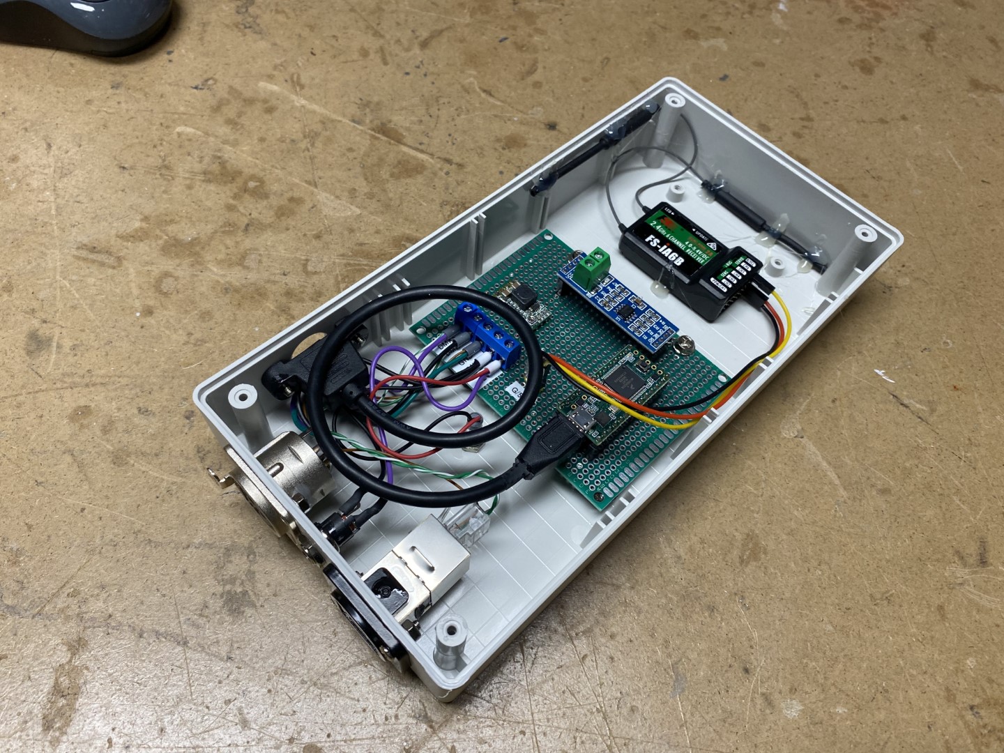
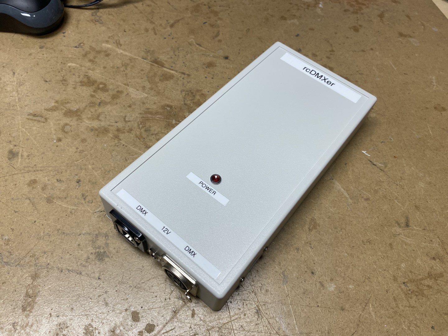
I added a XLR3 and RJ45 jacks for the DMX out…
Affixed the RC receiver and antennas with double face sticky tape ant hot glue…
Added a power led…
I now have 10 seperate channels of DMX controlled by the 10 different controls on the FS-i6
4 channels for the right and left joystick X & Y channels (each channel ranges from 0 to 255)
2 channels of potentiometer (each channel ranges from 0 to 255)
3 channels of 2 position switches (each channel is either 0 or 255)
1 channel of 3 position switch ( channel is either 0, 128 or 255)
In the code I can assign any DMX channel to any RC control (hence the panel mounted USB cable). I may want to add a OLED screen and rotary encoder to allow configuring channel assignments without needed to change the code but will probably not ever get around to it…
1 Like
Here is my code for rcDMXer
It’s extremely simple and could be cleaned up with for/next loops but it works…
I tried to include all relevant information in the comments…
rcDMXer_1.1.zip (2.1 KB)
This is for I-BUS but I do have other code for PPM if anyone is interested…
2 Likes
If you are wondering about animatronic control and why I am using DMX with Eddies various actuators, here is some decent information:

And here is some general information on animatronic control I have gathered:
And some animatronic projects information:
1 Like
After a bit of bit wrangling I managed to get the dual motor code working…
This allows for two seperate PID instances so each motors response can be tailored…
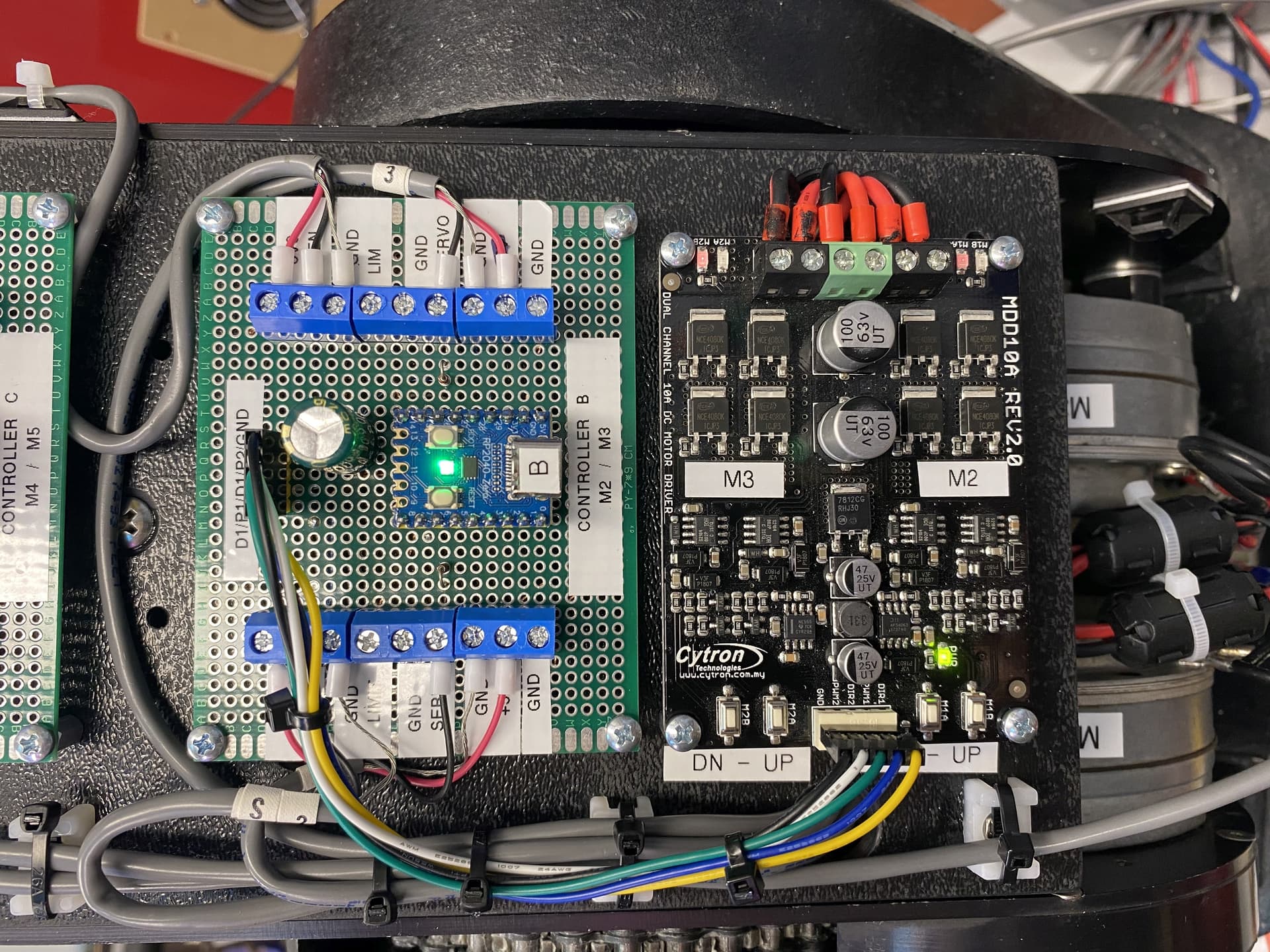
Also mounted the position sensor for the second motors axis…
Now I have 3 of the 5 motors under control:

Next is Eddies head. It has 2 motors for rotation and tilt. Along with 2 servos for the mouth and horns. First I have to rip them all apart, clean and grease them, then put it all back together. Then hook it up to the second motor driver board.
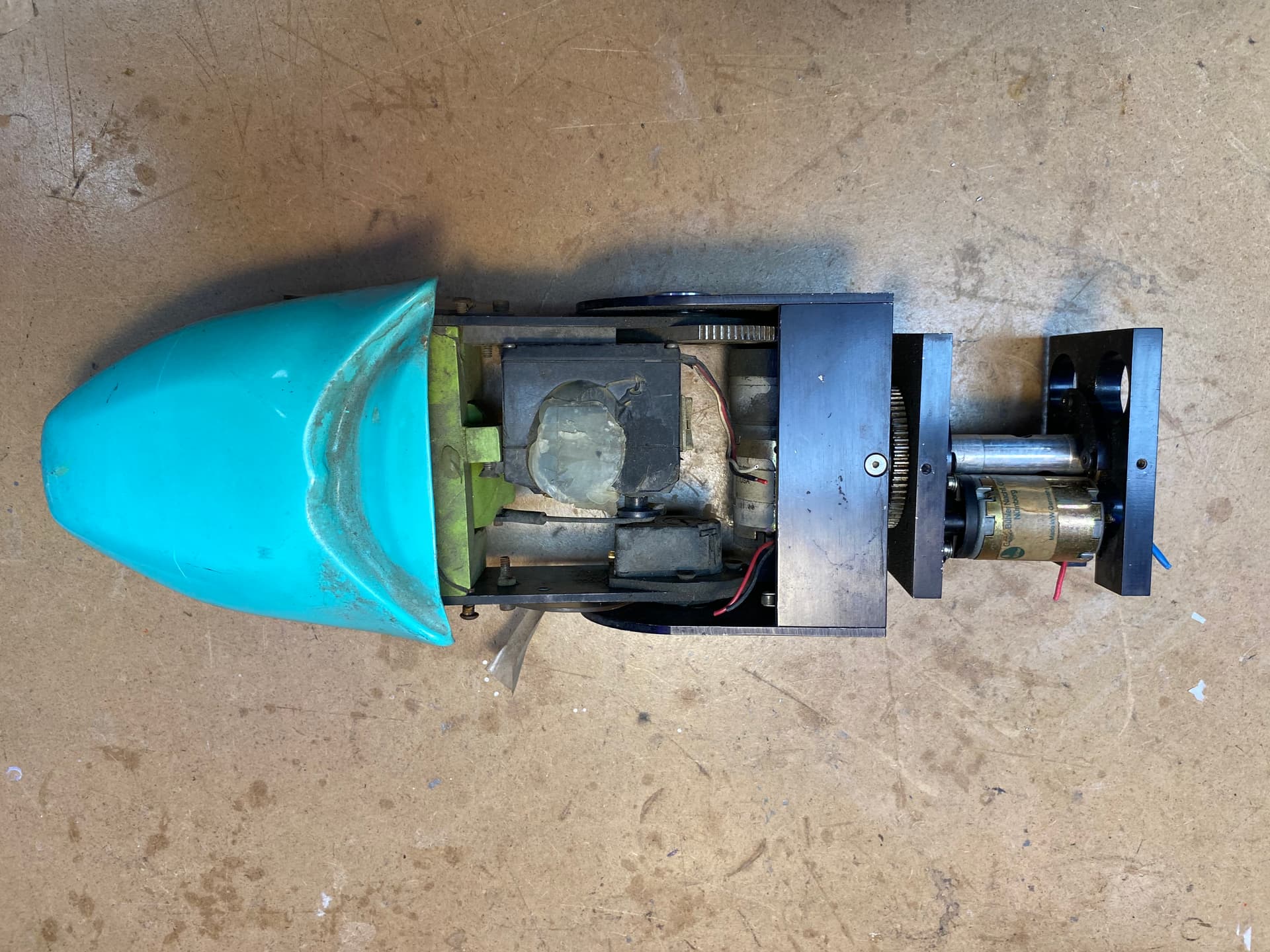
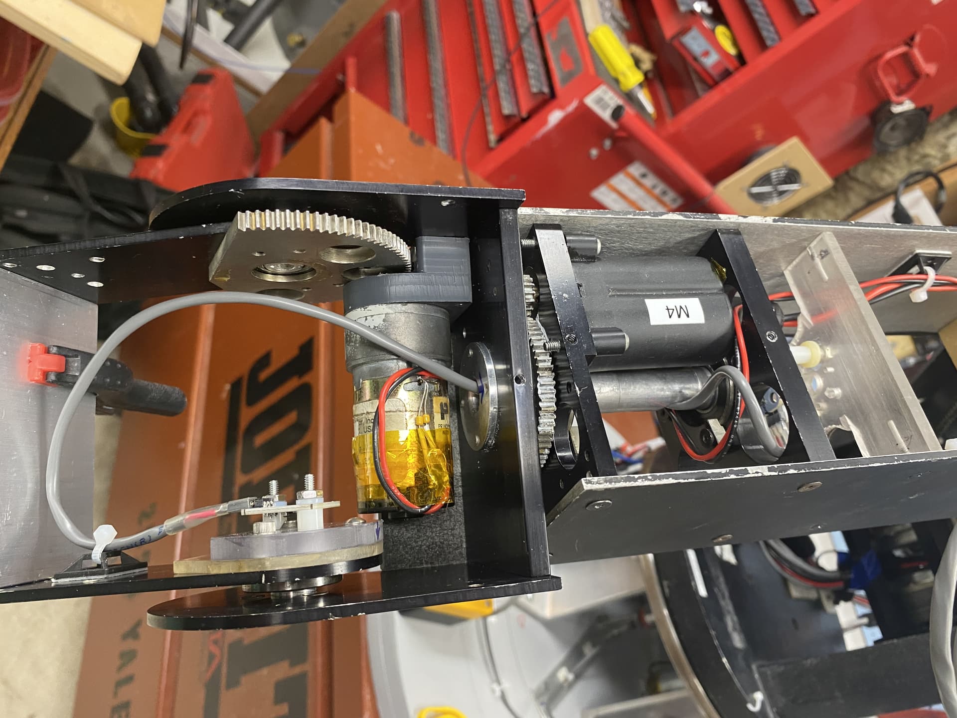
Started working on the head mechanism:
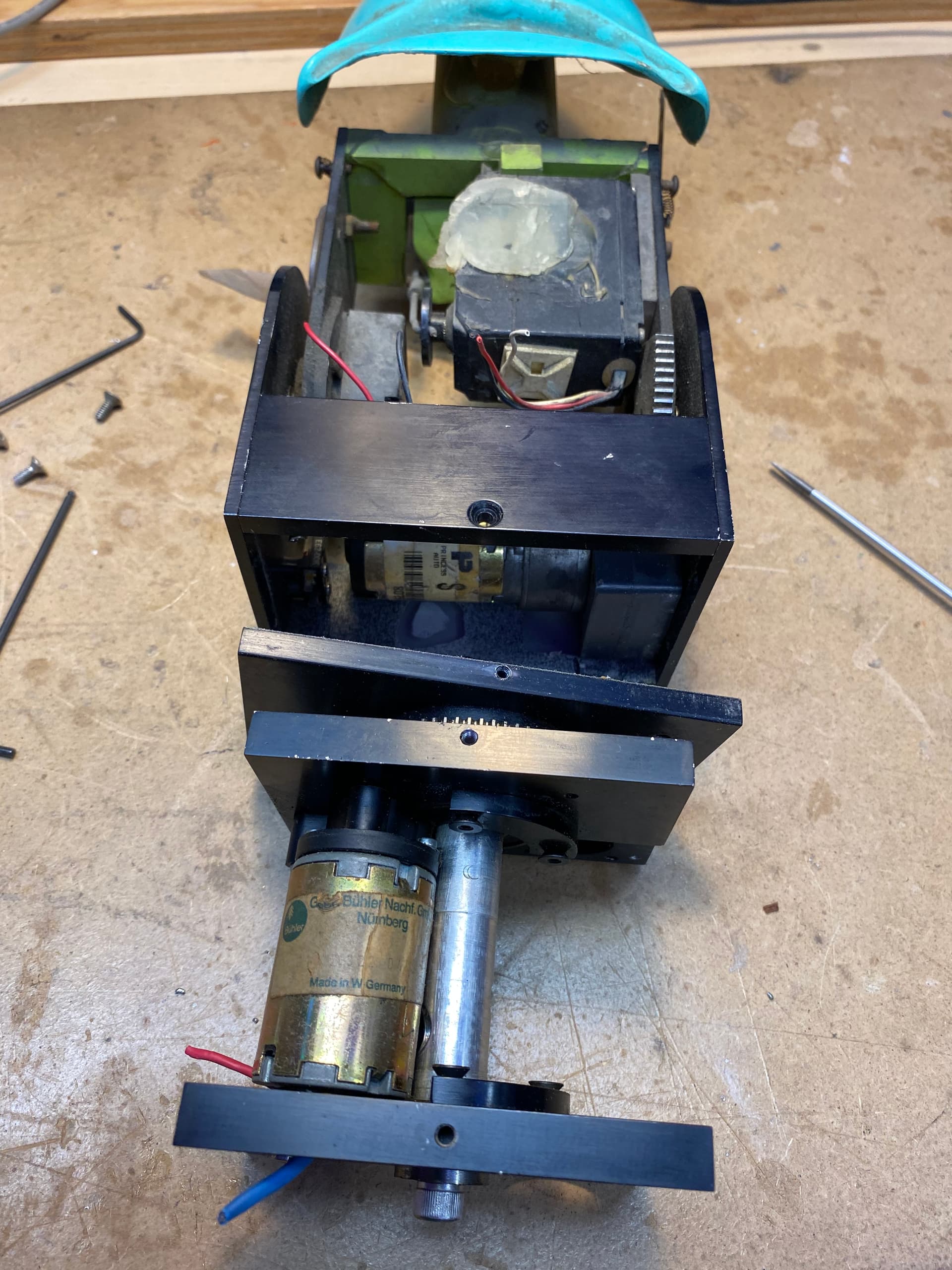
Got it into pieces:
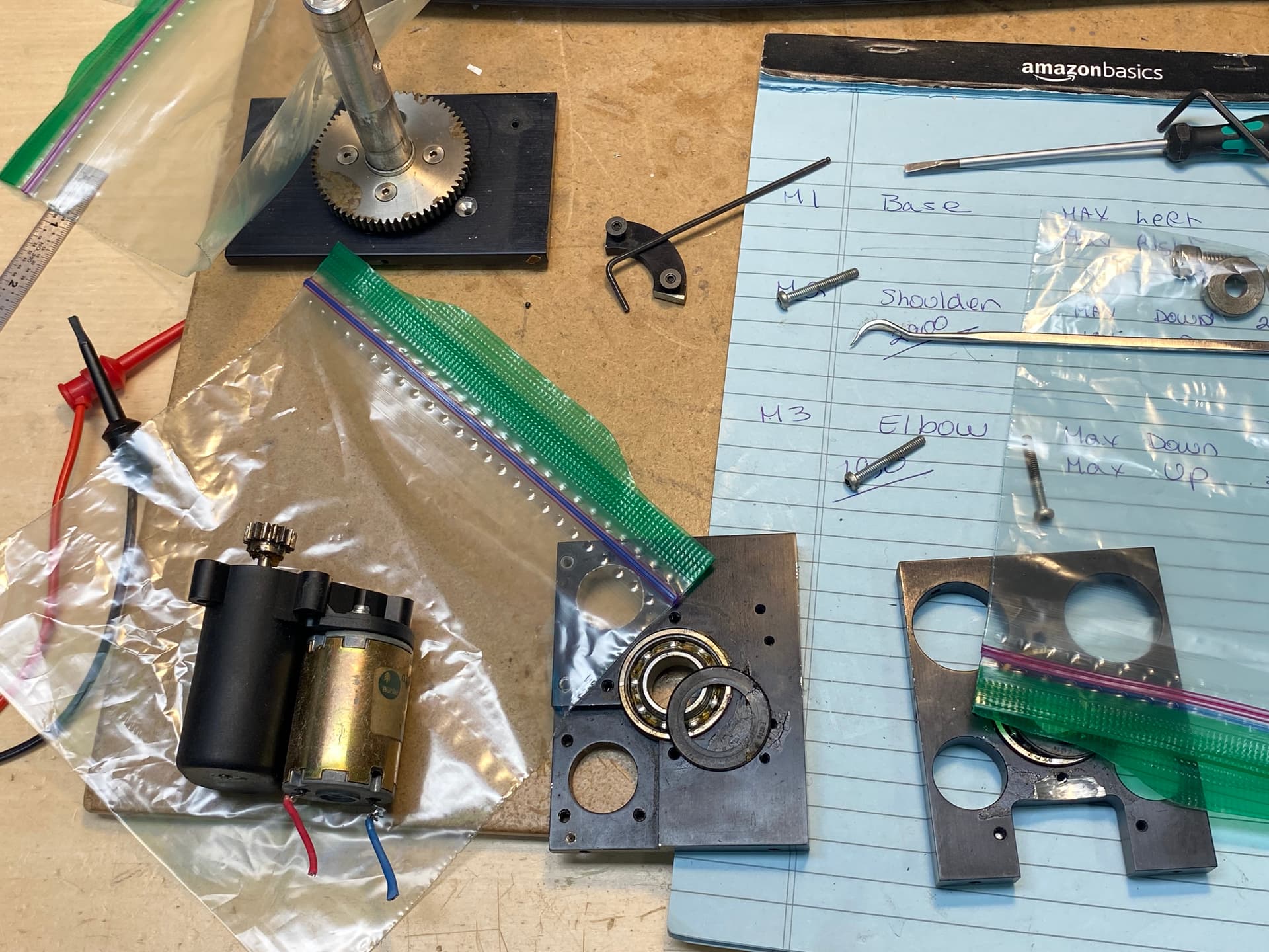
Bearing were gunked up with hardened grease…
Soaked everything in solvent…
Cleaned out the bearings…
Refilled them with new grease…
Want to check the lubrication in the gearbox but discover the gear on the motor shaft was glued on with epoxy:
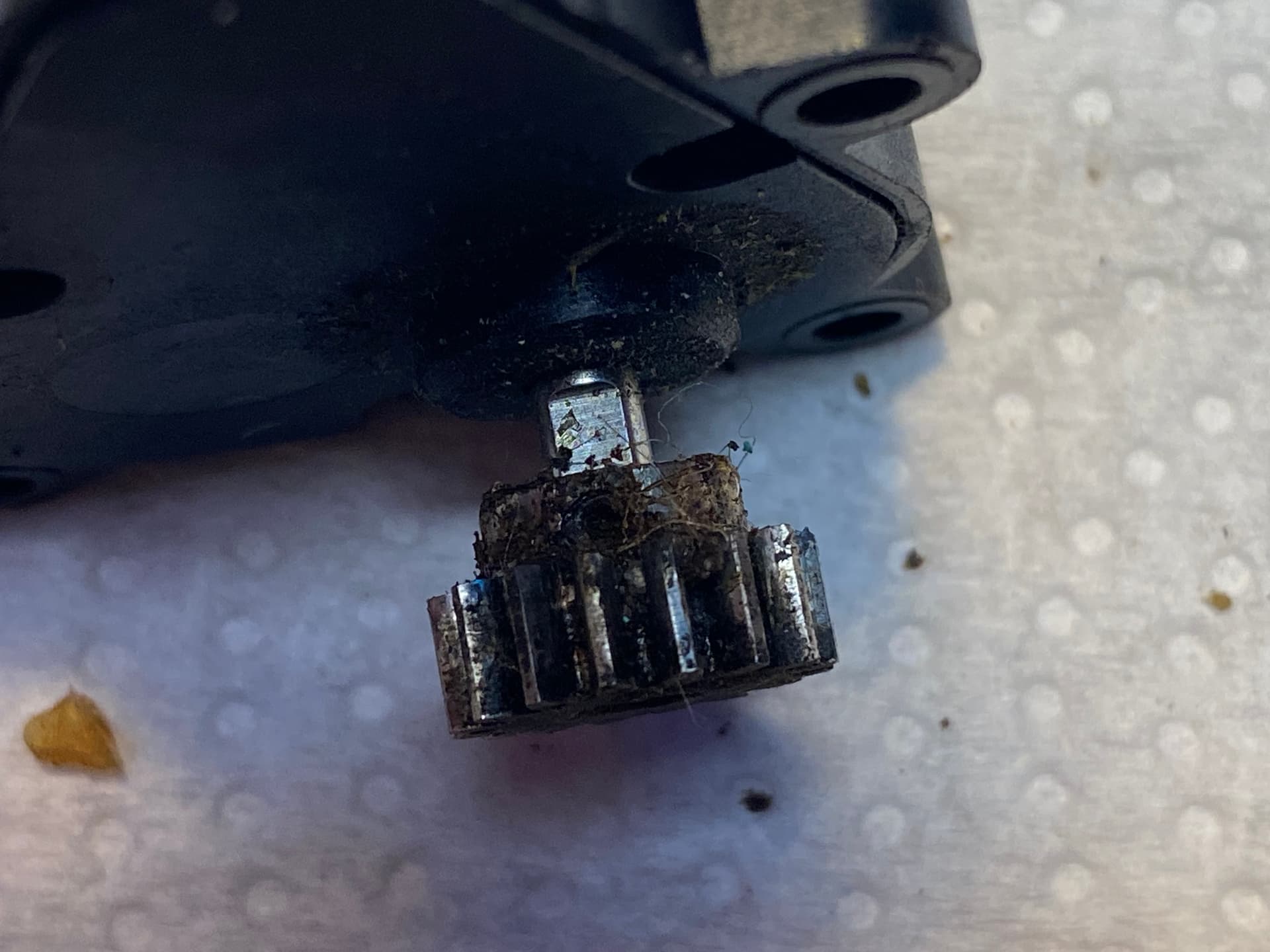
This was done on some of the other motor gears but they were large enough to re-tap and put in a proper set screw. Not sure about this one…
To complicate things the gear isn’t mounted square on the shaft so it wobbles quite a bit:

Got to figure out options for pulling the gear off, heat may be the easiest but the gearbox is plastic (though the gears all seem to be metal)
2 Likes
I tried testing the motor in place and even though the gear wobbles I think I will leave it as I suspect trying to straighten the gear will cause more more troubles than it is worth…

This larger gear it meshes with is for the head swivel and it will only move about 45 degrees back and forth at the most
2 Likes
for pulling that gear off maybe you just need to shield it from heat? like some ceramic tile or something as a shield
I decided to leave it as it is…
I opened up the gearbox and turns out most of the gears are plastic so figured applying heat or too much force would probably wreck the whole thing…
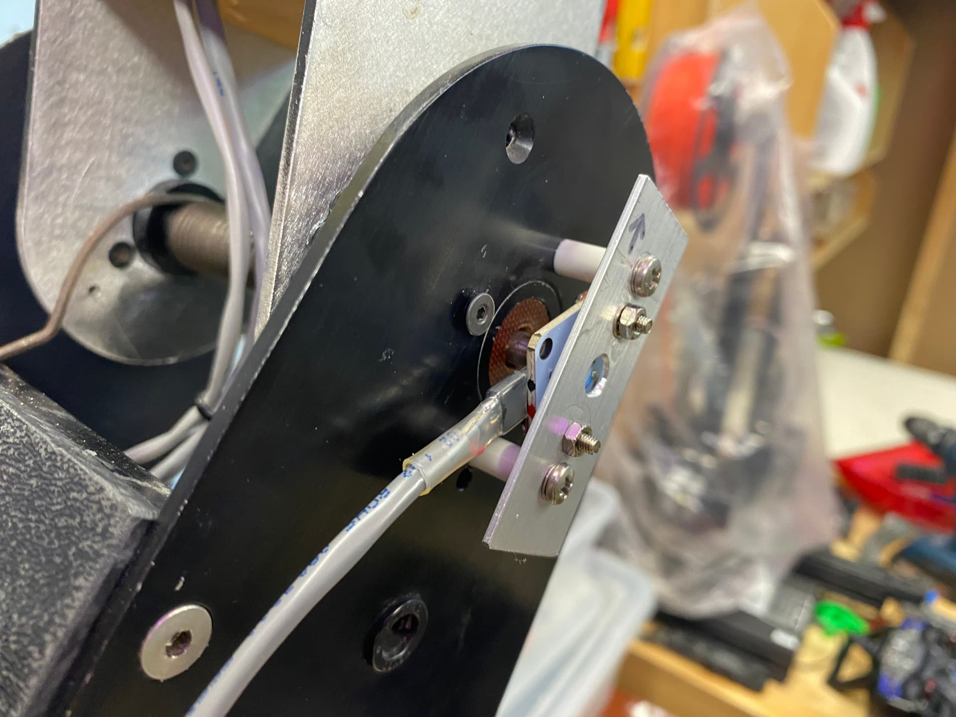
Got the next motor cleaned up, re-installed.
Rigged up a position sensor (I love these AS5600 sensors) and got the controller board configured…
This motor rotates the head
I know have 4 of the motors configured and controlled by the PID motor controllers and each is controlled by a seperate DMX channel…

Next the head tilt mechanism and motor…
That will be the last motor that needs to be controlled…
The mouth and horn mechanisms are controlled by servos so I won’t need to build controllers for them…
1 Like
And a note on the “Murder Bot” issue… Eddie’s robotic mechanisms do pack a wallop and can hurt. Especially if they are suddenly moving to a new position. I have installed an emergency stop switch and have a seperate power switch for the motor power. After a few whacks I have tried to develop some protocols to follow in my compact shop.
I try to do this before energizing the motor power:
- Make sure the DMX controller is on and connected to Eddie’s controller
- Make sure the DMX controls are set to known position that matches Eddies existing axis positions
- Make sure nothing is within Eddies reach
Only then do I power up the motors…
I have made the mistake (many times) of powering up the motors with the DMX position data being way off the current axis positions and having everything move at once to go to it’s desired position. Have the PID does slow down things but it can still cause pain if you are not prepared for it…
I may also put in a time delay to ensure the controllers have time to boot up before the motors can move.
There is also an issue where if the servo controller doesn’t see a DMX signal when it starts up it decides that all channels get a 0 input and this can make the axis suddenly move to the 0 value position. I may rig up a circuit that “intercepts” the DMX input, monitors it and if there is no valid DMX signal it fakes something. Animatronics typically default to a center value but in my case I may make the pan/rotation axis default to mid position but the up/down axis default to the up position in the assumption this would be the safest…
2 Likes
After a bit more thought I’m gonna rig up a controller to control the motor power in the following ways:
- Give some amount of delay from power up before motor power is available. This will make sure all motor controllers have started up before motors can move.
- My DMX servo controller has 8 servo outputs (7 are in use so far) but it also has 8 PWM LED outputs. I plan to use some of the LED outputs for eye and mouth LEDs but won’t need them all. I will have the controller monitor one of the PWM LED outputs and only enable motor power if the DMX channel is set for 255.
2 Likes
With initial testing of a few motors moving at the same time all was good except I would seem to get a crash of one of the motor controllers… I suspected it was EMI interference from the motors but I had already done pretty much all I could to fix that (next step was possibly using shielded cable for the motor leads). But it only happened when I moved things at max speed and that was never going to happen in normal operation…
But with the additional motors it was happening more often. Again only when moving multiple axis at full speed (so not an issue during normal planned operation) but was still really bugging me.
Once I really started digging I realized that the 12V 12.5A power supply was actually dropping it’s output to almost zero for just a short time when it got hit with the load of multiple motors moving quickly… It was so quick (much less than a second) that some of the controllers didn’t even notice (they have larger filter caps).
I tried a few other power supplies and ended up finding a 12V 29A supply that has no such issues. Only problem is that it’s bigger than the old one and I have to re-jig all the power cabling and possibly move the controller mounted on the base…
Here are all the 4 controlled motors moving at once (as fast as they can) in the full range of their motion:

3 Likes
For startup safety, maybe copy what RC transmitters do: If, on powerup, any INPUT axis or switch is not in its zero/default position (i.e. throttle zero, rudder, elevator and ailerons centred), refuse to send any OUTPUT signals until the controls are zeroed.
And, to go a step further, have a separate arm switch that can’t be toggled unless the INPUT controls are zeroed, and which, when actuated, implicitly zeroes all the OUTPUTS, so that nothing will automatically move from its current position once armed.
And a dead-person switch on an elastic lanyard is probably a good idea…
1 Like
I have finally got all 5 of the DC motors setup with encoders and controllers:

Here are some pics of the electronics:
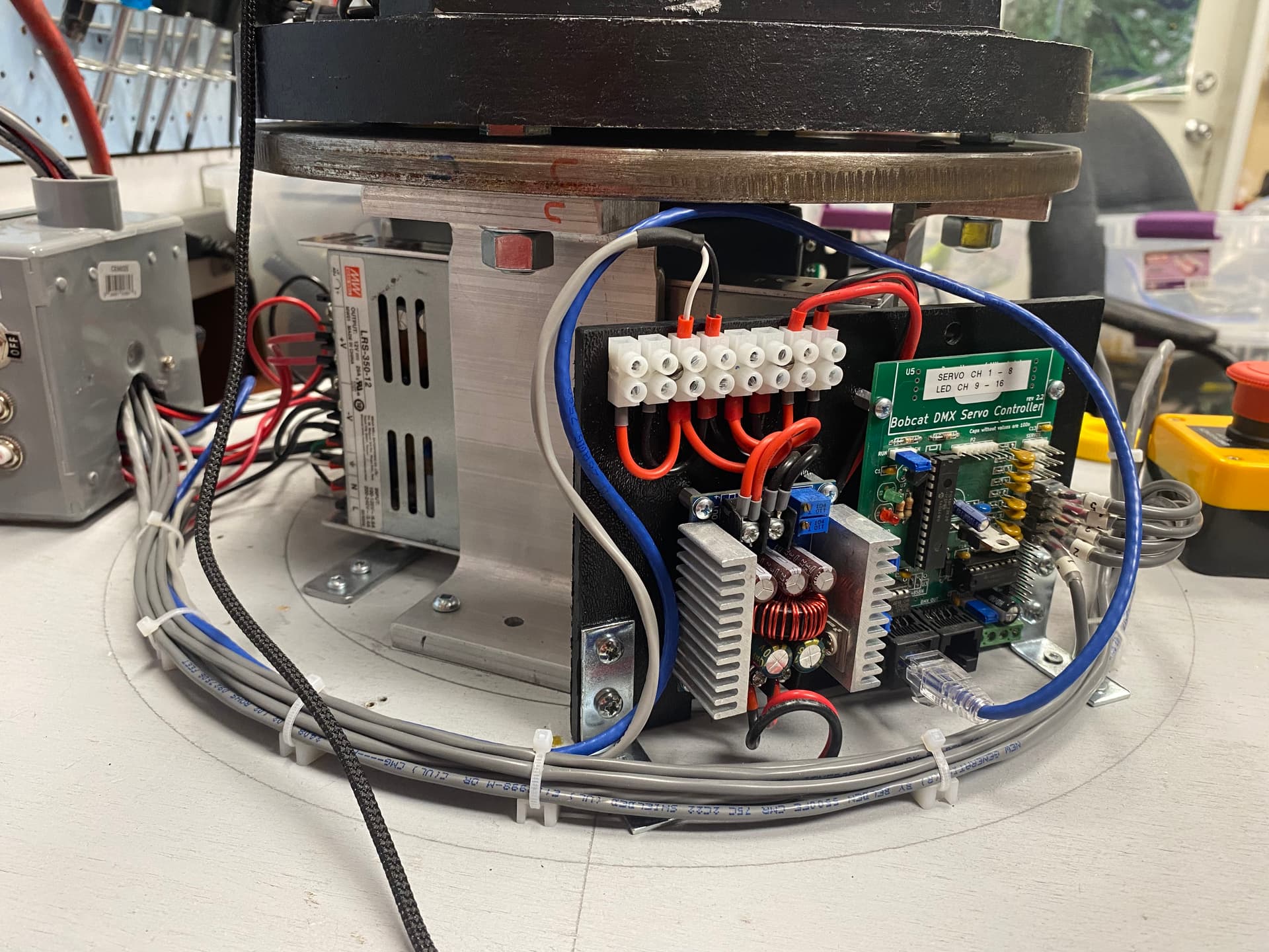
12V power supply, 5V power supply (steps the 12V down for the controllers and the servos) and the DMX servo controller (converts the DMX signal to the RC servo PWM):
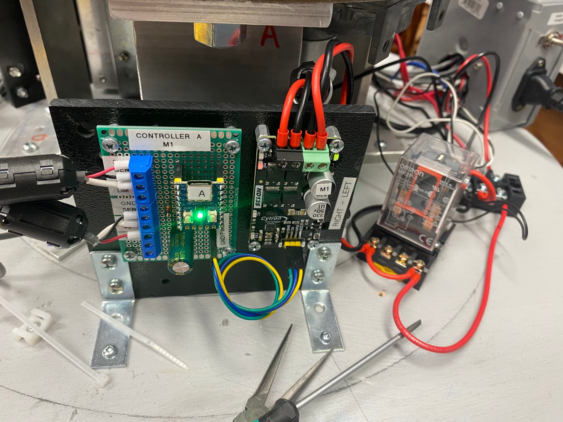
The RC PWM to DC motor/encoder controller (single motor version) for the base rotation, its motor driver and the relay to control the motor power (right now just hooked up to the Emergency Power Off button):
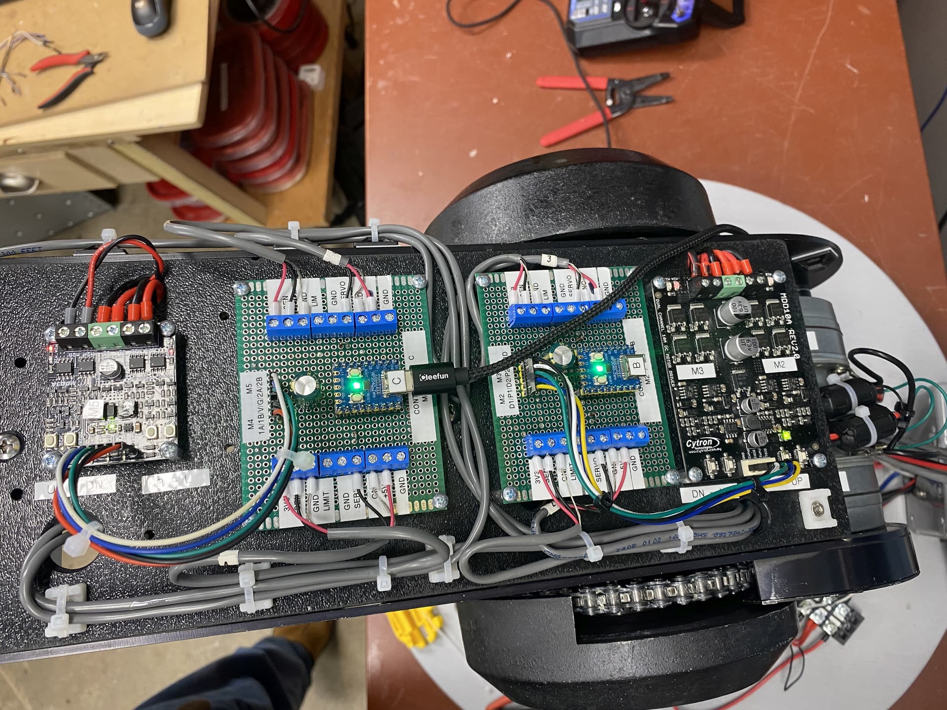
The RC PWM to DC motor/encoder controllers (two of the dual motor versions) with motor drivers:
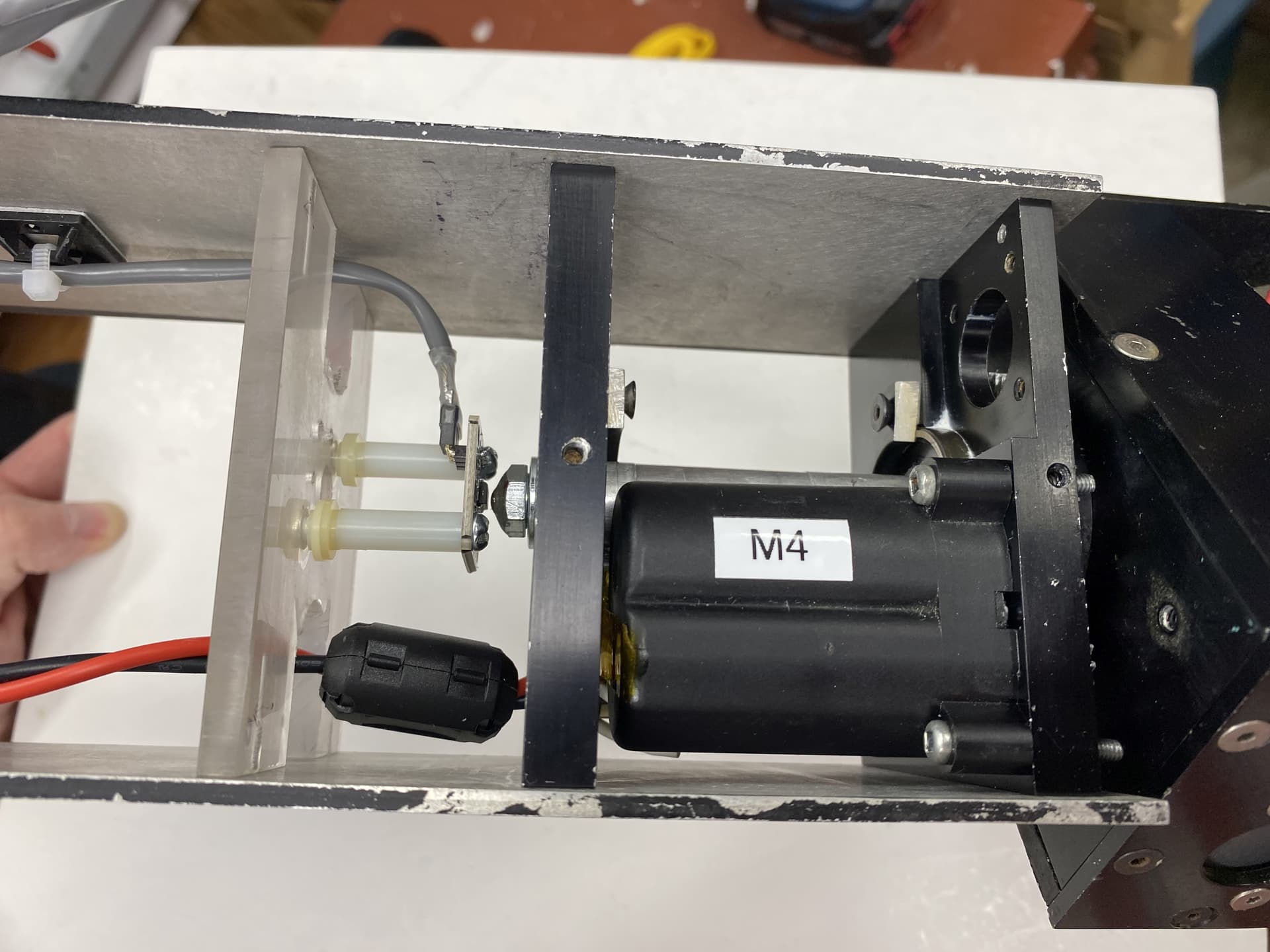
And here is the final motor for the head tilt and it’s encoder:
The DC motor controllers will hopefully have been the hardest part. Next I have to put the head and mouth back together with its servo driven jaw and same with the horns. The existing mouth servo is toast so I am using a new one. It’s smaller so have to figure out some new mounting.
Also have to properly mount the horns as the mechanism that moves them was just glued to the head…
Then I have to figure out how to put all the body parts back together and mebbe a paint job…
2 Likes
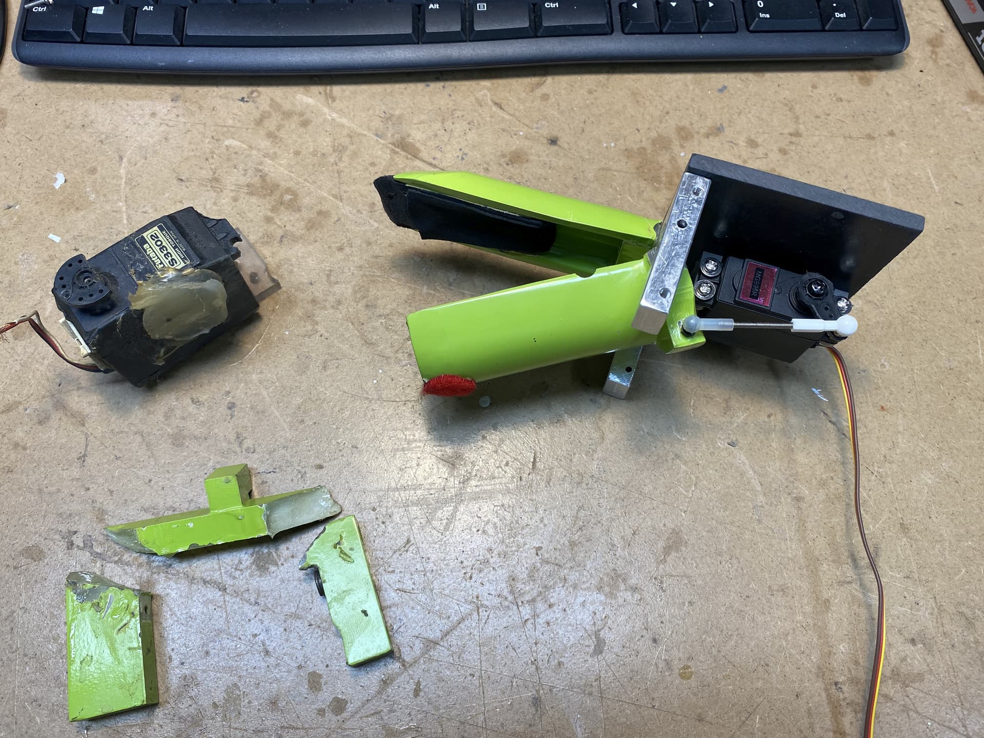
Had to do a little dragon dentistry today and rebuild the mechanism for Eddies mouth… The original frame was cracked (it was made of plastic) and the original servo was toast… Made a new frame out of a piece of aluminum (lots of drilling, cutting with jig saw, filing to make smooth, more drilling and tapping) and then installed a new servo…
Eddie can talk once again… Or whatever dragons do…

1 Like
Made a bit more progress. Got the mouth mounted and connected to the servo controller:

In theory this was gonna be the easy part as the servo connects directly to the servo controller (compared to the previous complexity of having to make the additional controllers for the DC motors). However I did need to limit the range of the servo to avoid it jamming up. The servo controller supports this but it’s configuration software was written in 2011. I thought it was having issues in compatibility mode (under Win10) but found the same issue running in under XP… There actually may be a bug in either the controller firmware or the configuration software when you try to set the limits on one of the servo outputs (changes work on all the other outputs it seems).
Anyways next I have to get the head back together and get the horns working…
2 Likes
Fun fact: Vimeo was a spinoff of CollegeHumor. The name was a cheeky reaction to Youtube (“Me” instead of “You”, plus “Video”)