Eddie the Animatronic Dragon

So a while back someone posted (Free robotics character used in film/commercial) wanting to get rid of an old animatronic prop dragon that had been gathering dust. It had been fabricated by a propmaker in the building that had closed shop some time ago and left it behind…

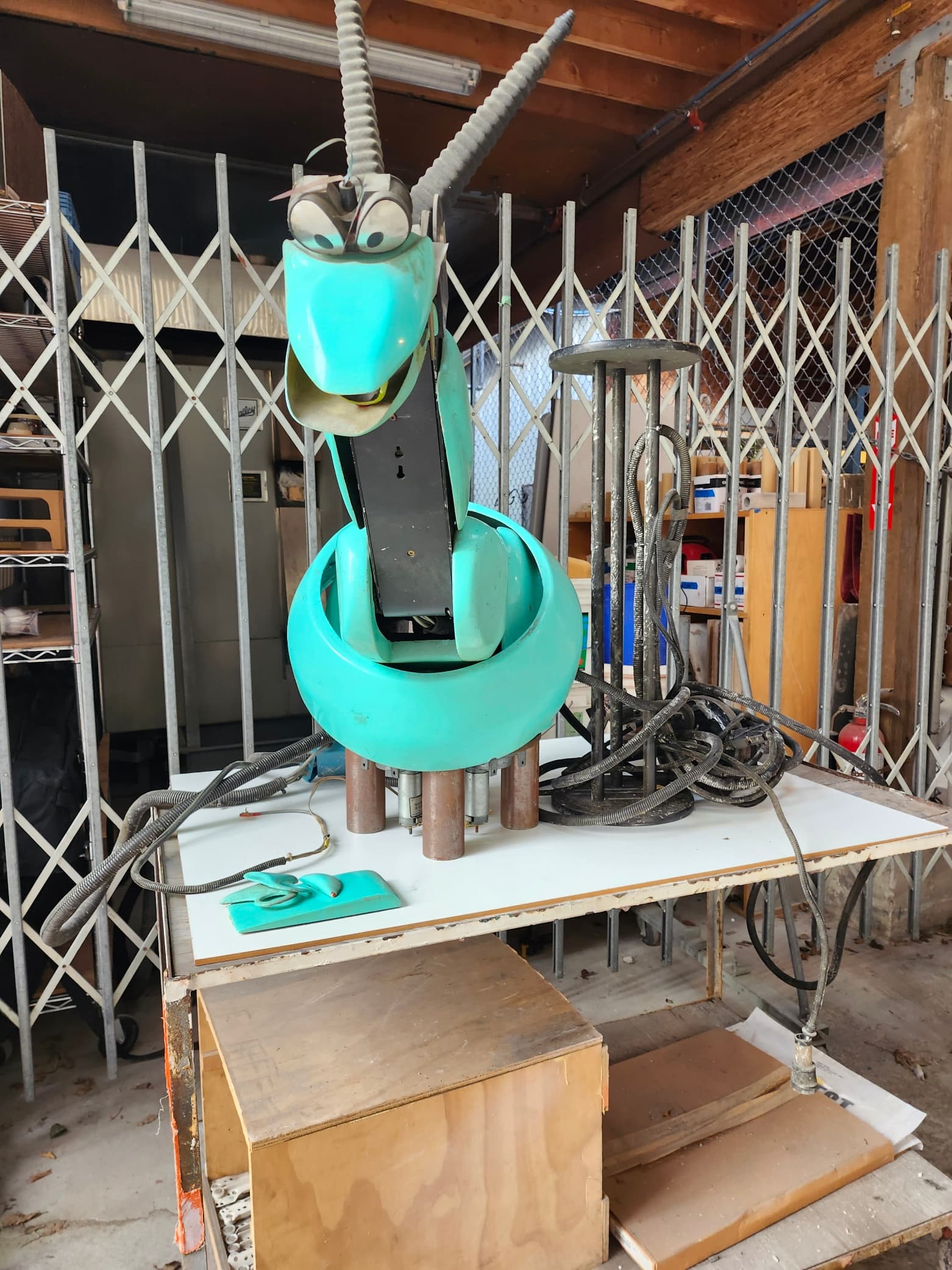
It was heavy, kinda bashed up, missing any sort of controller, had some broken bits, was very dirty but I couldn’t say no… I wanted to bring it back to life in the hoped of having it as a greeter at the Space or if nothing else being able to terrorize my cats…

This post will chronical the journey…

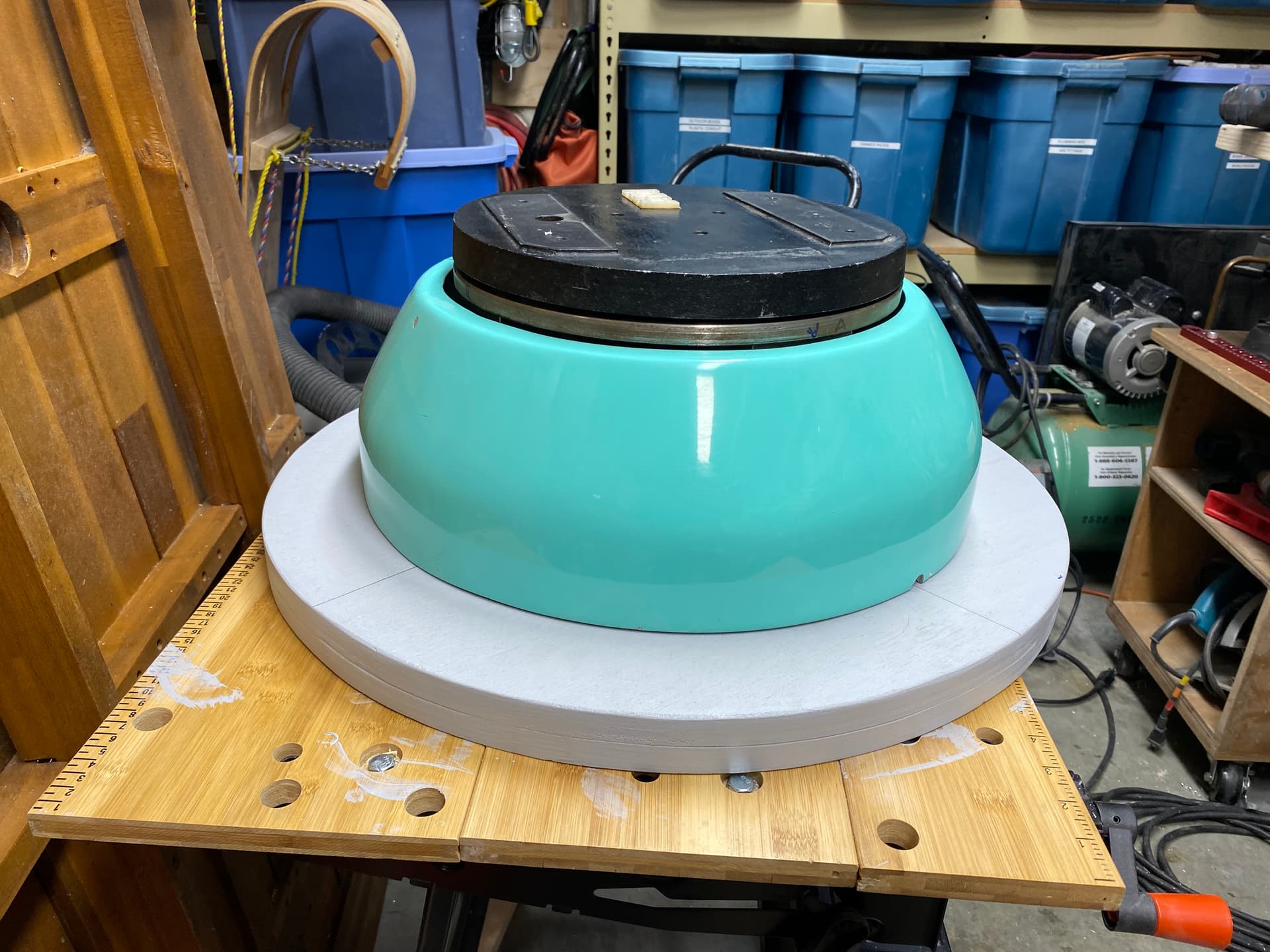
First I had to get it home. It weighs a ton… Definitely more than 150 lbs… I managed to wrestle into my vehicle and get it safely home into my garage .

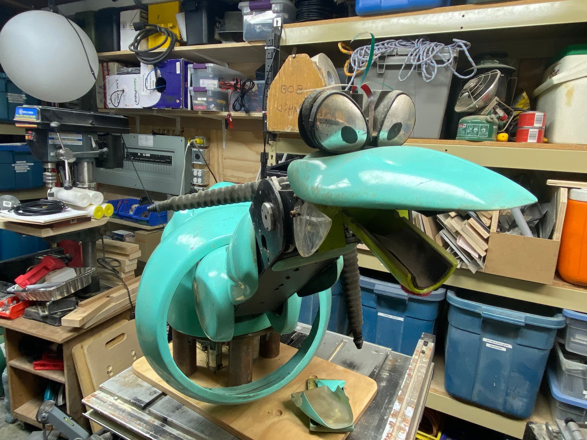
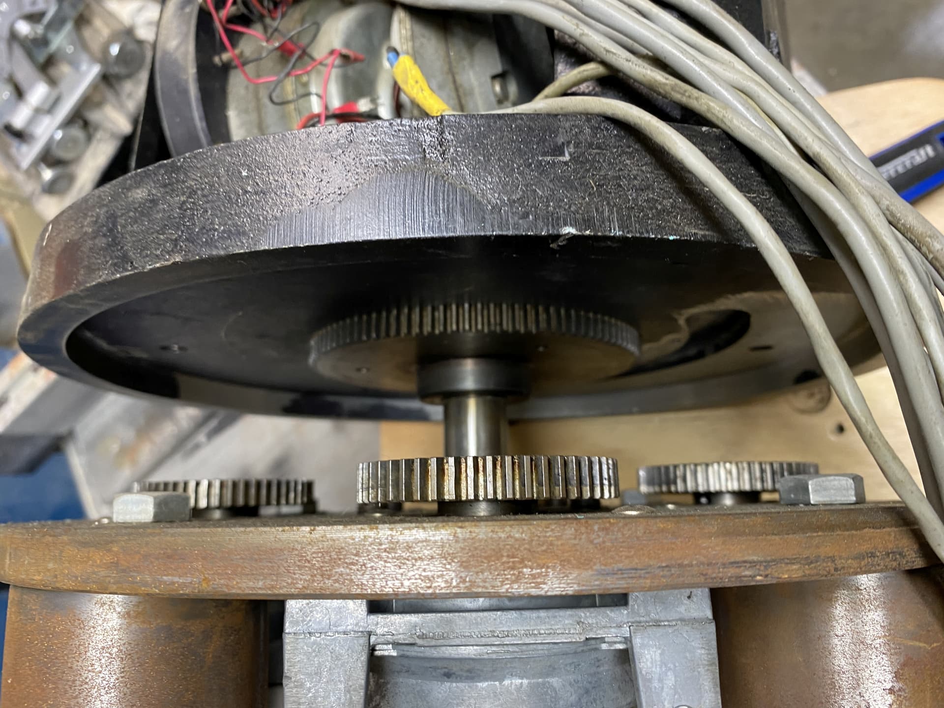
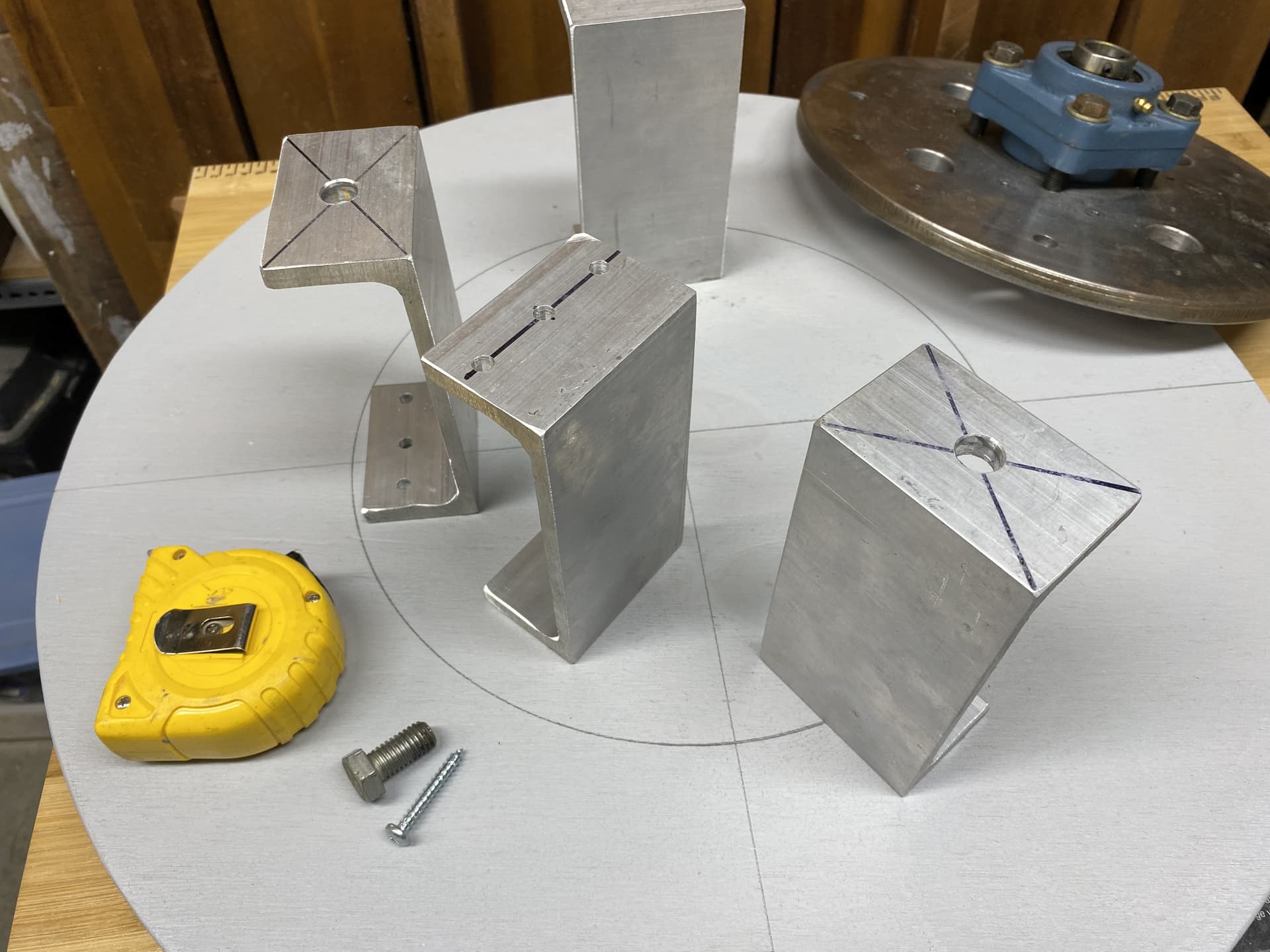
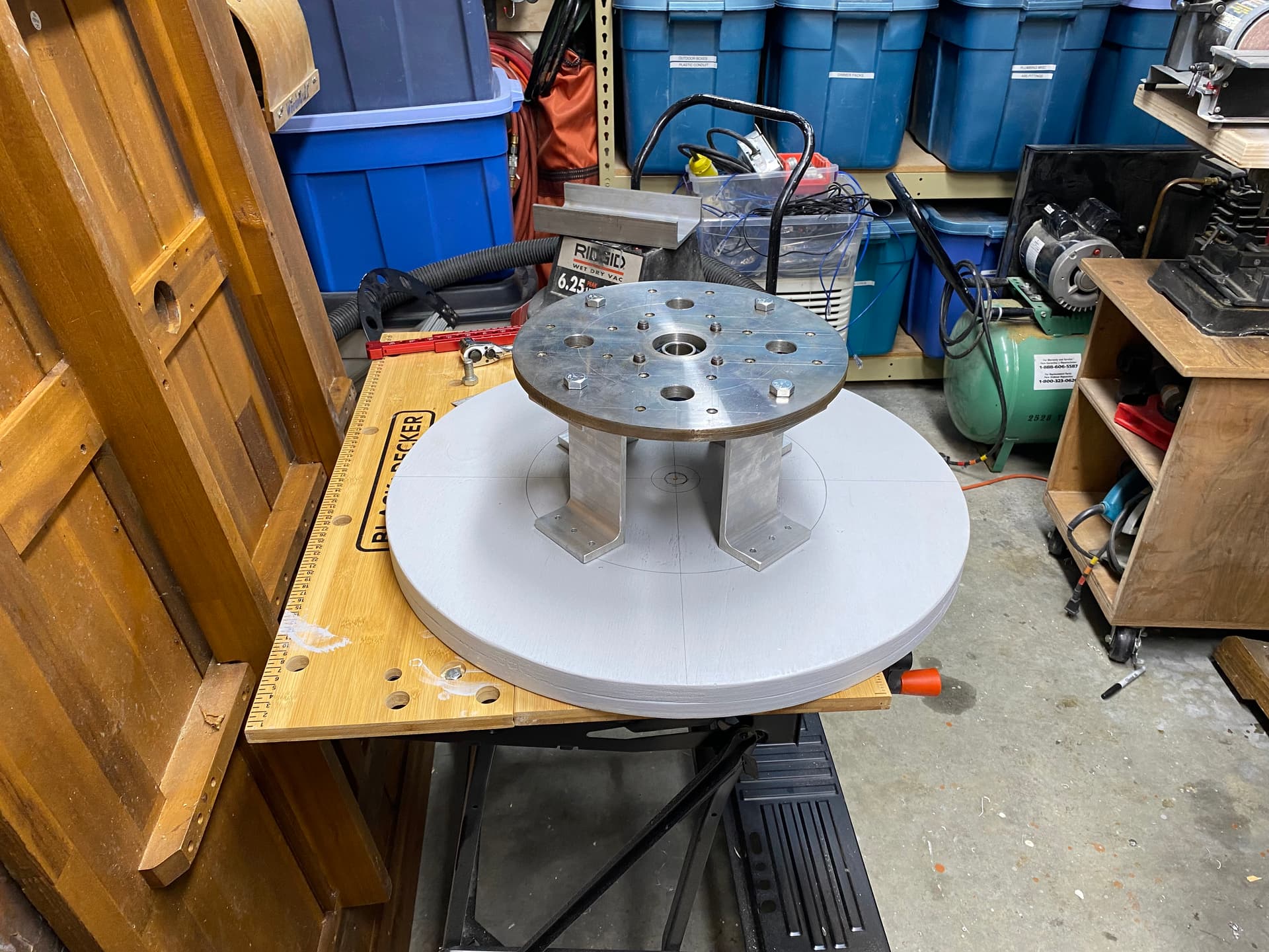
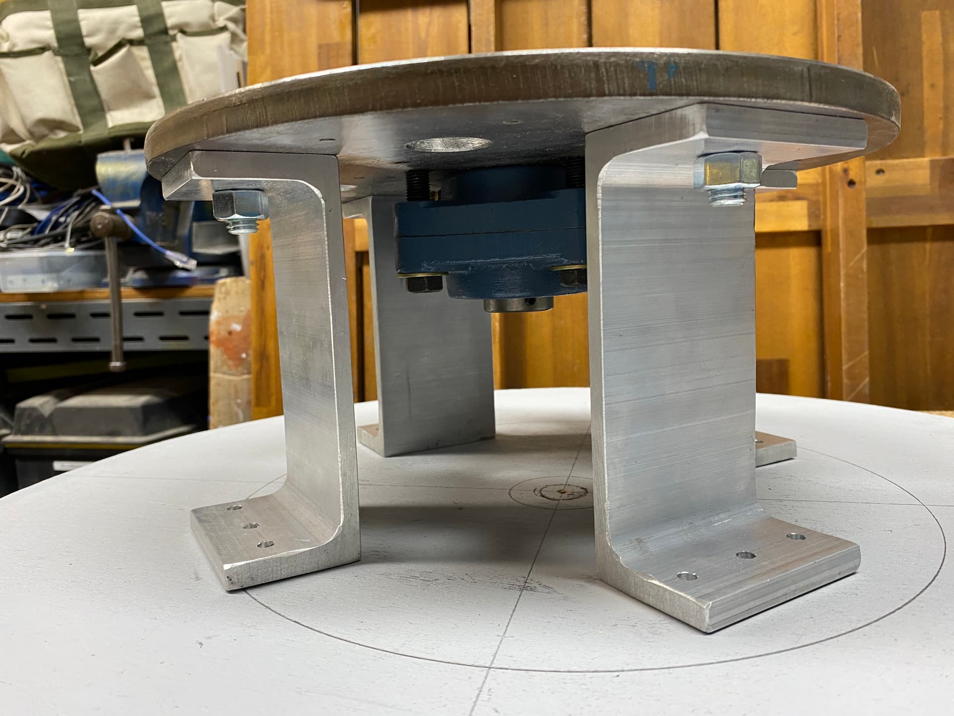
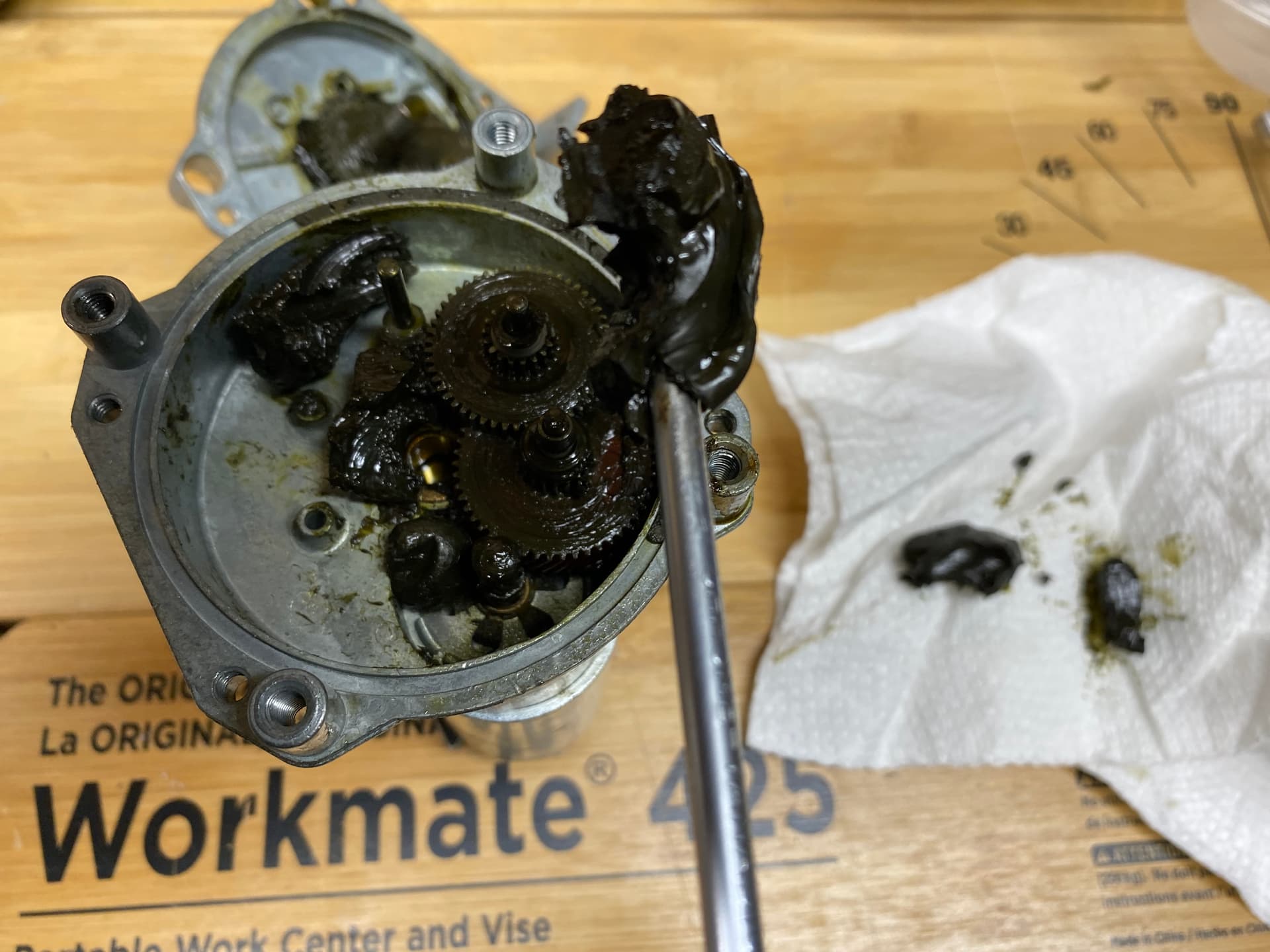
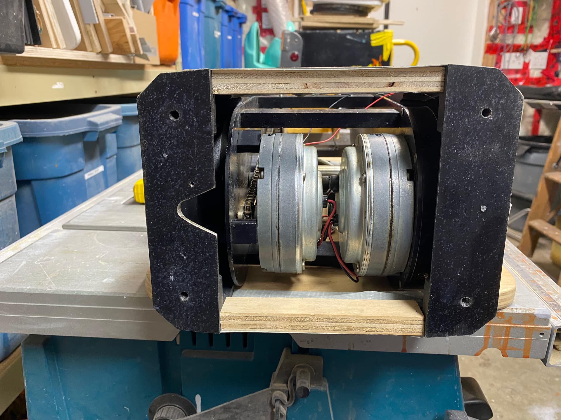
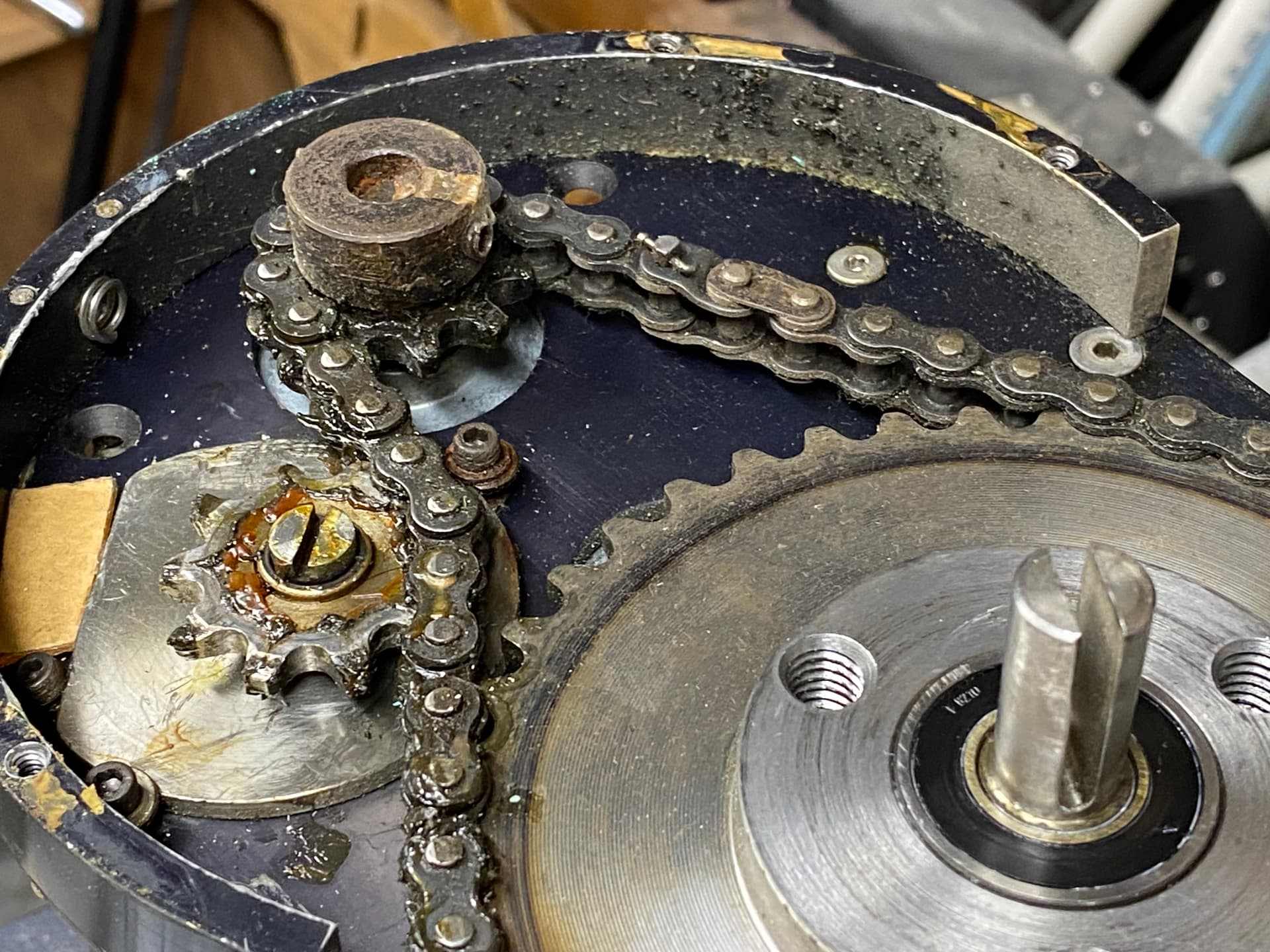
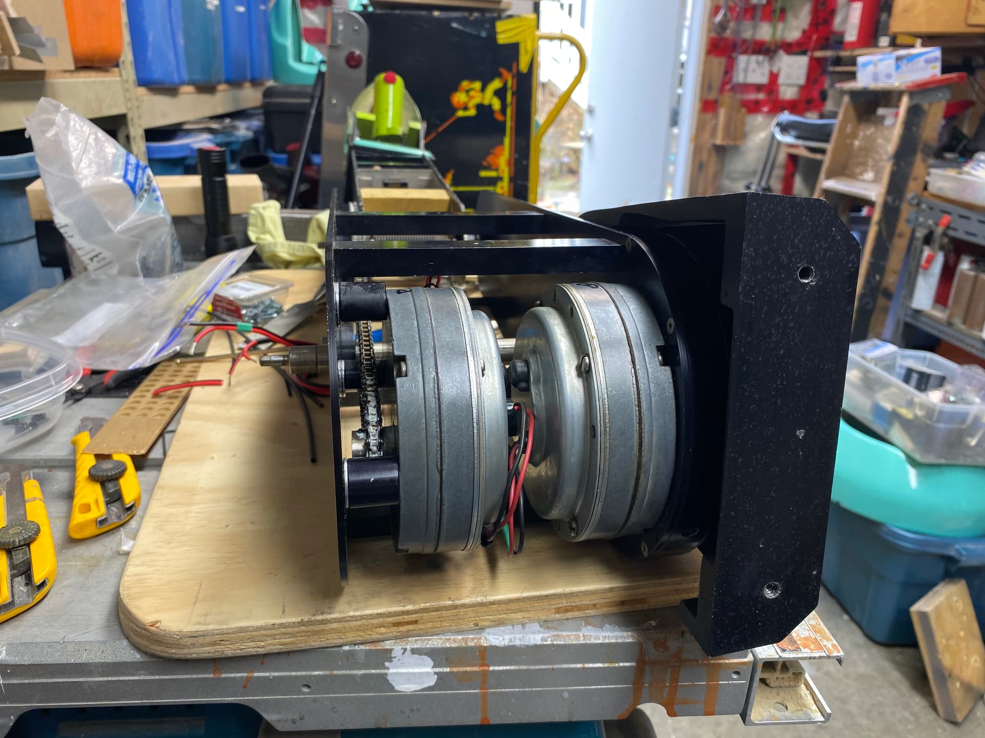
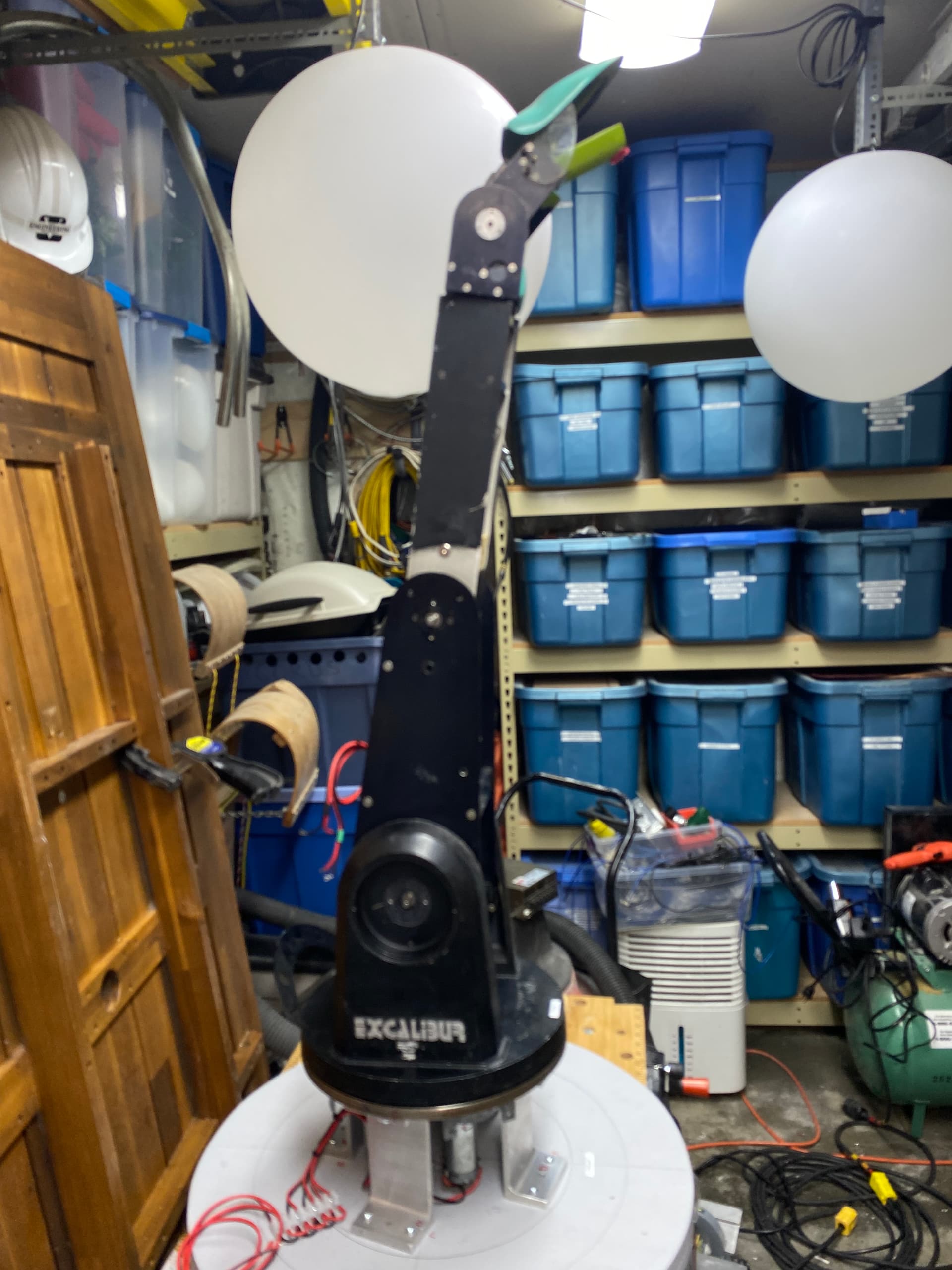
Next I pulled off all the fiberglass body parts to reveal its guts.

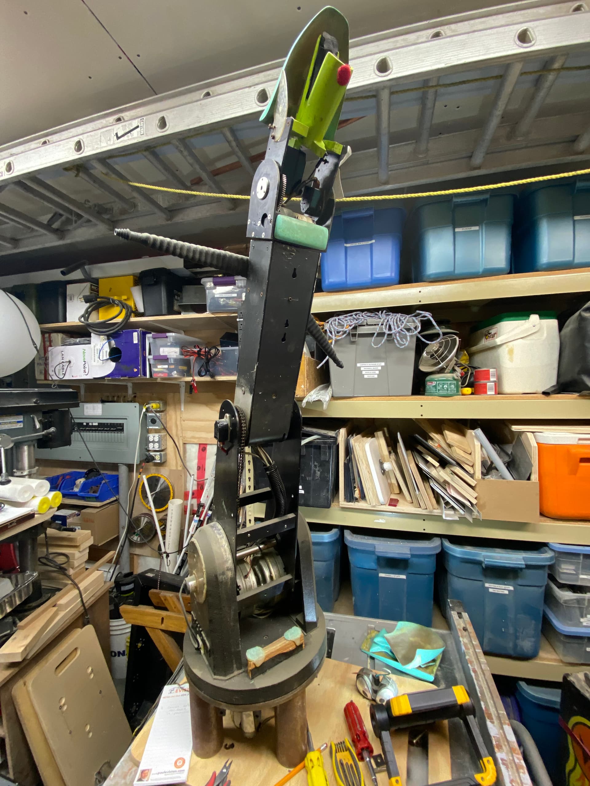
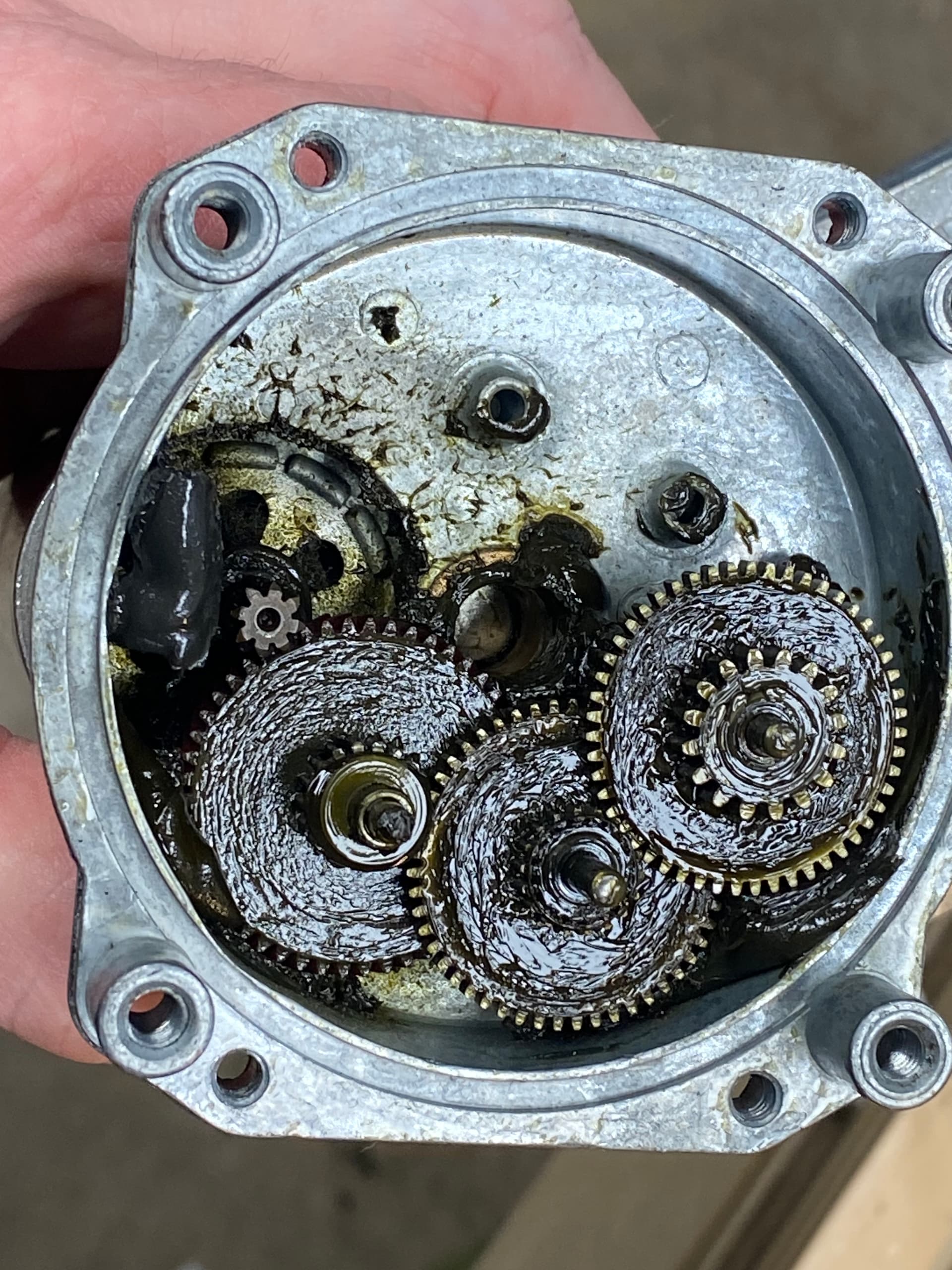
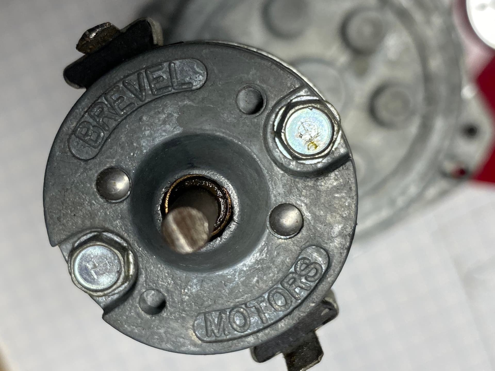
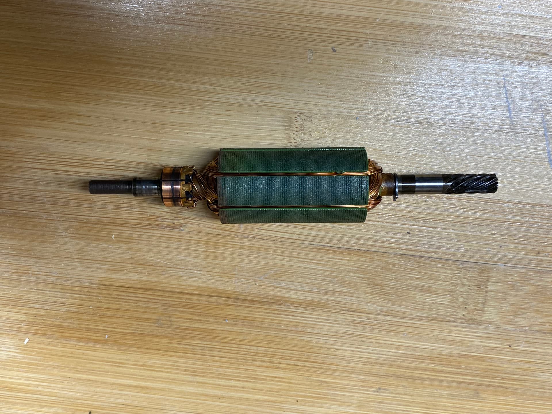
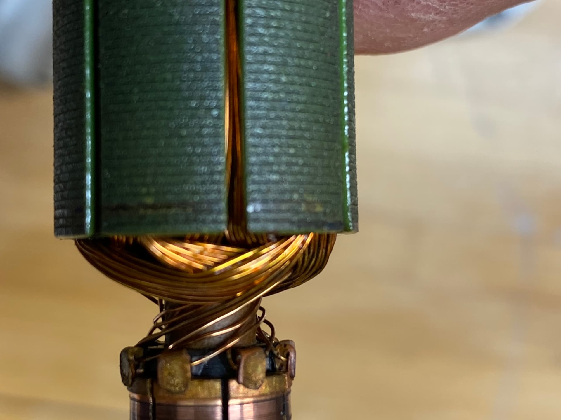
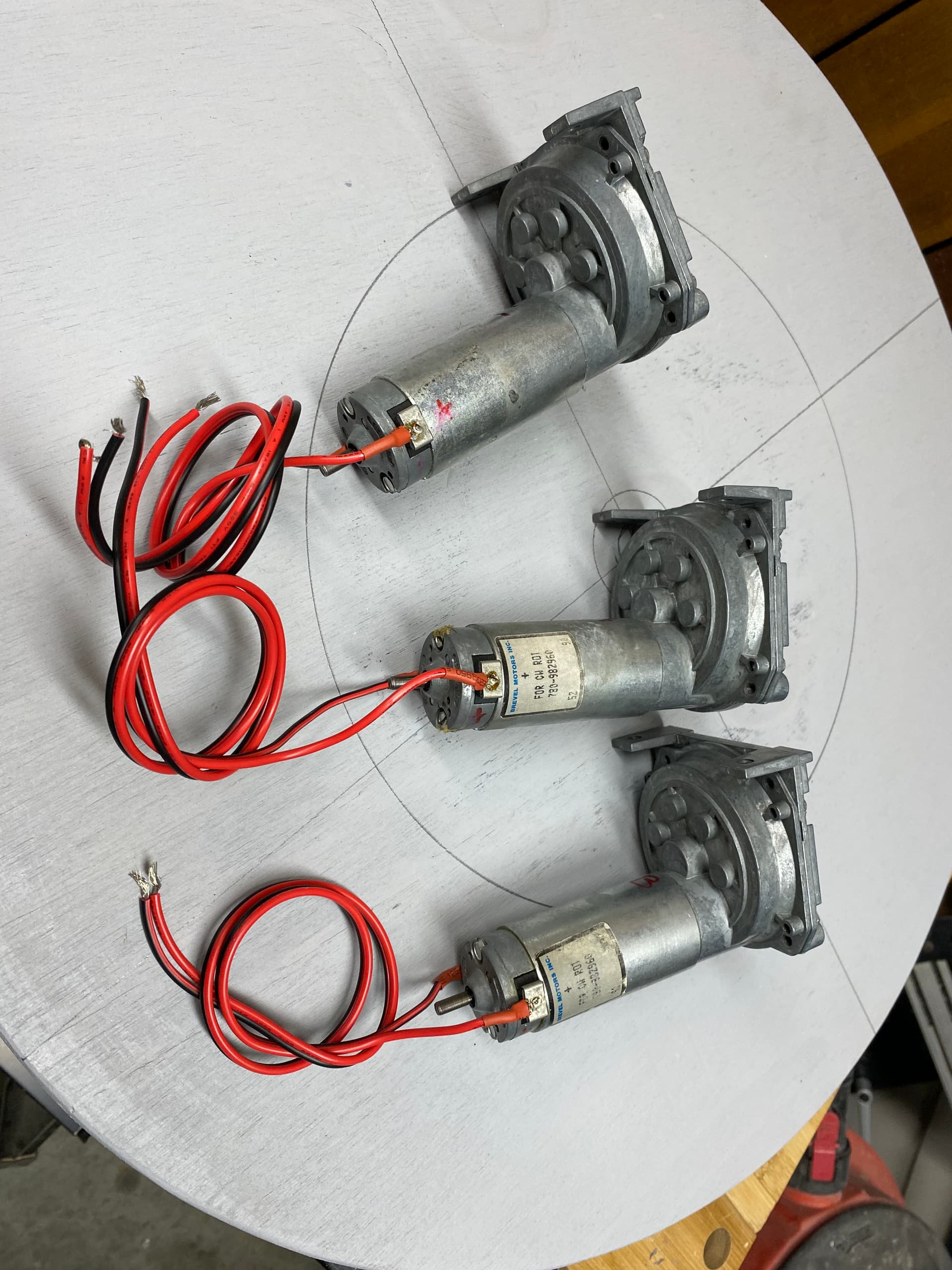
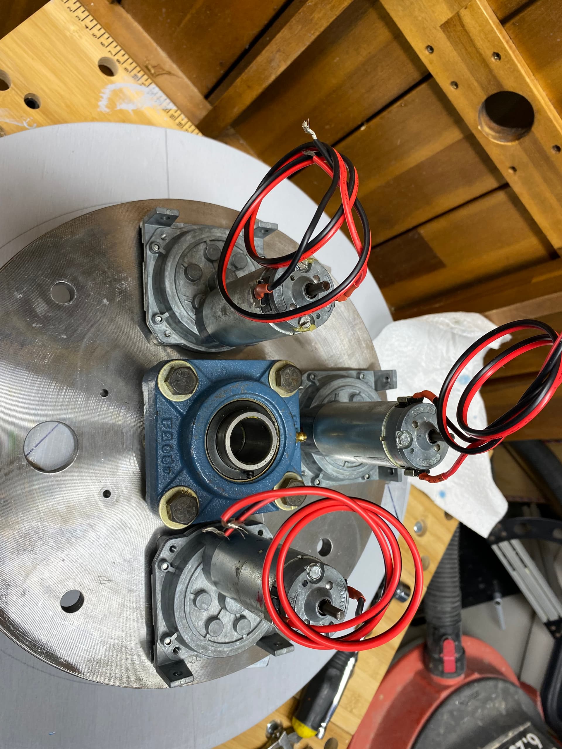
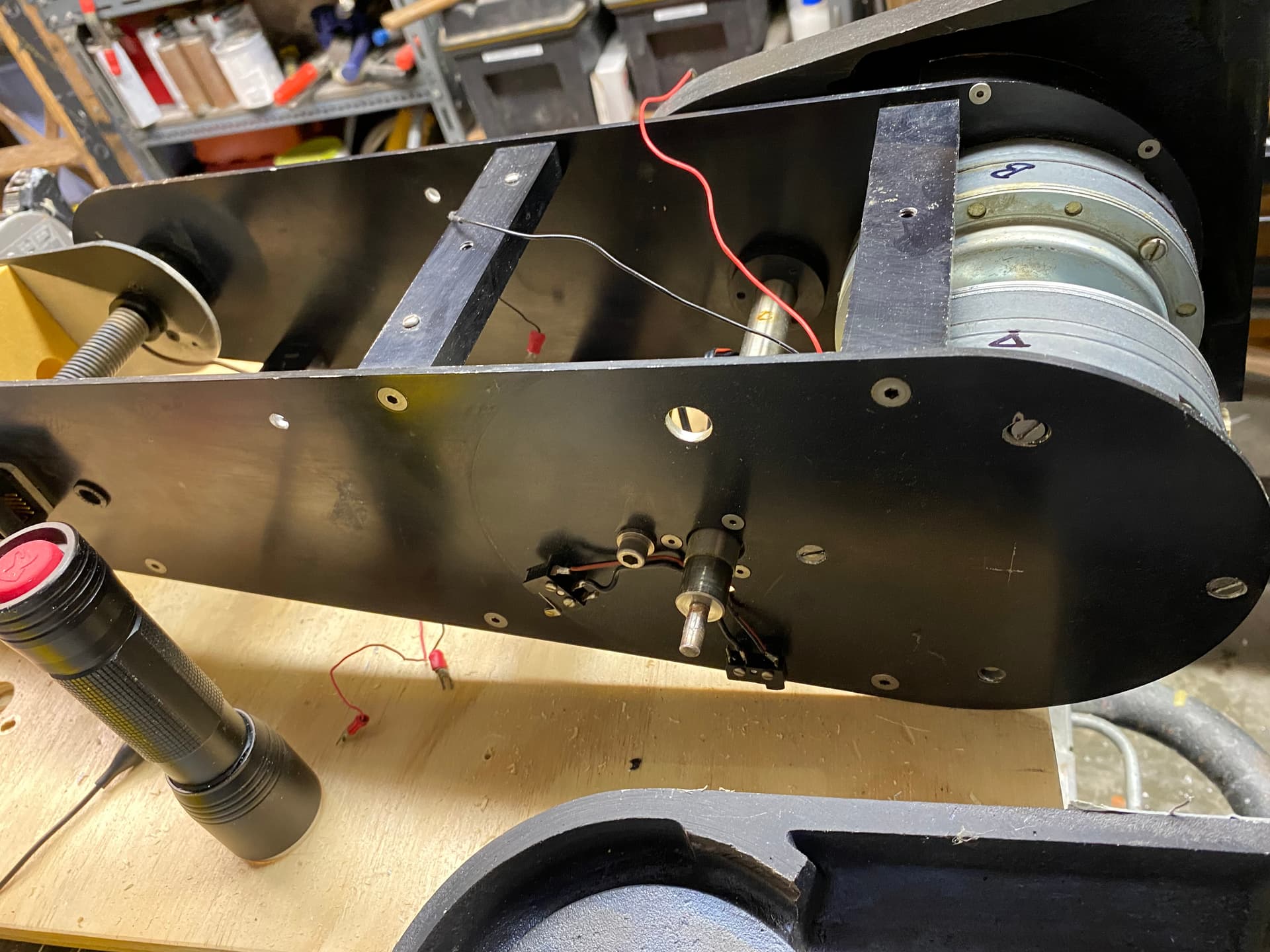
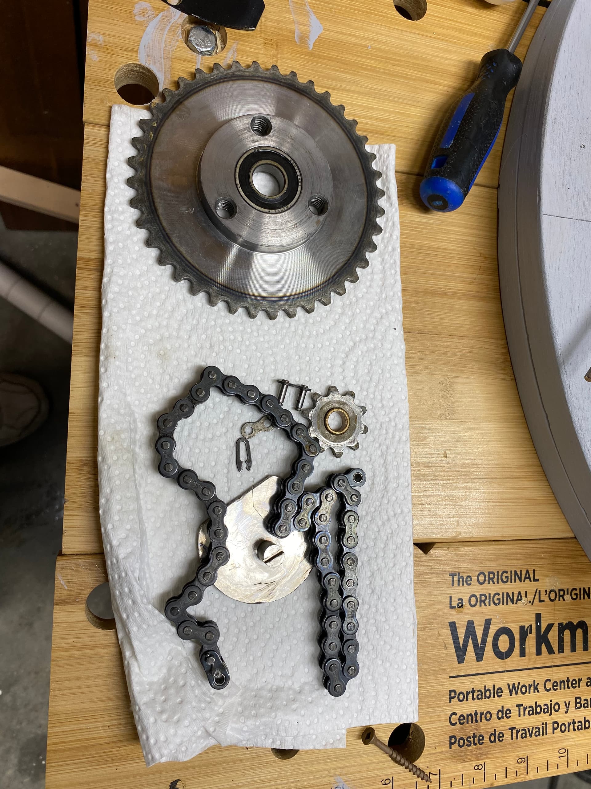
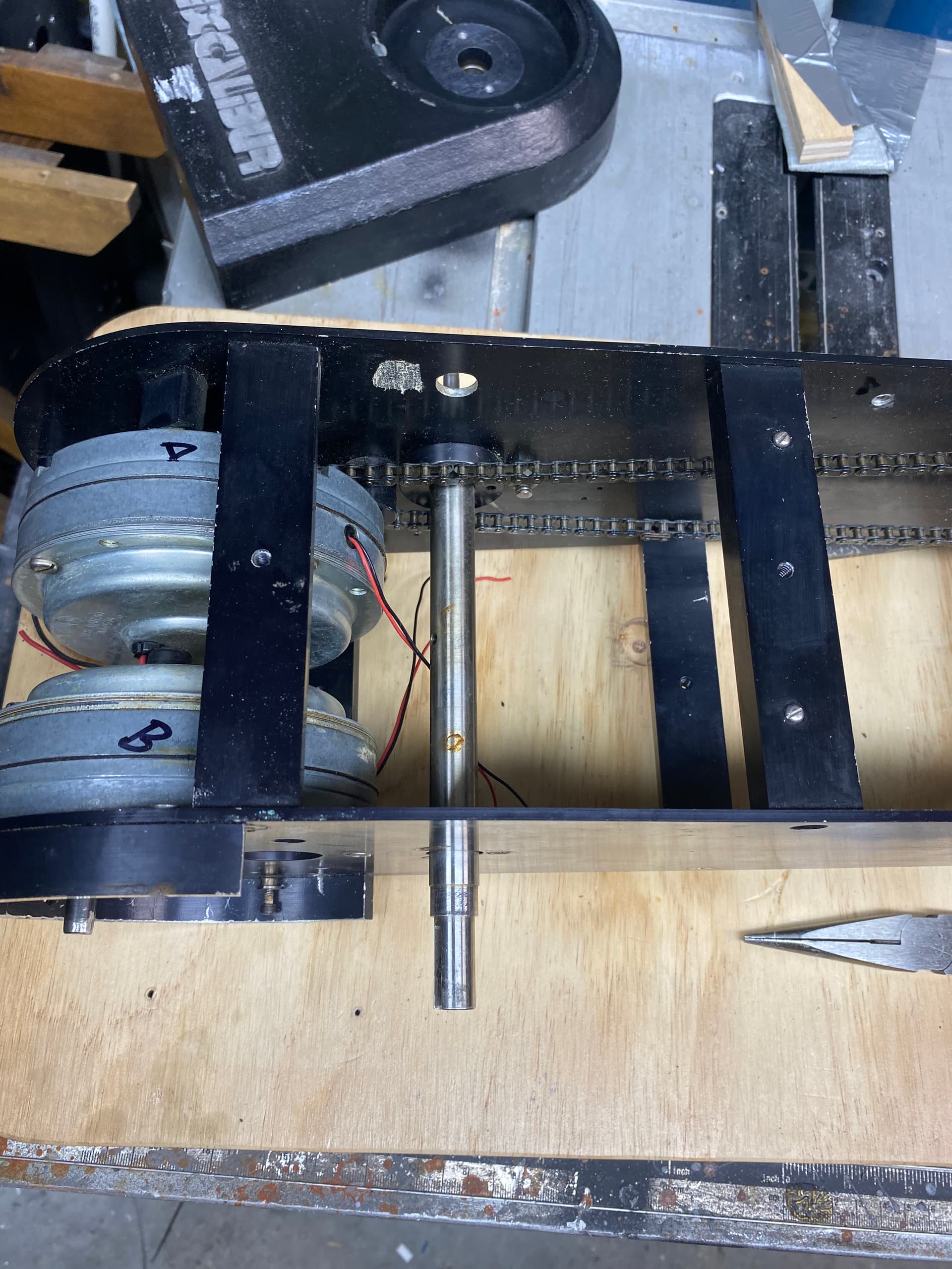
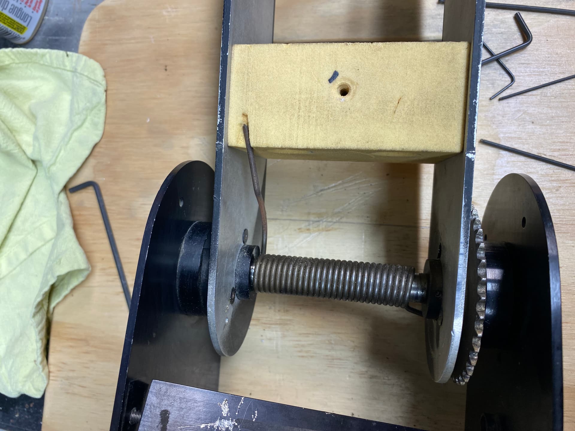
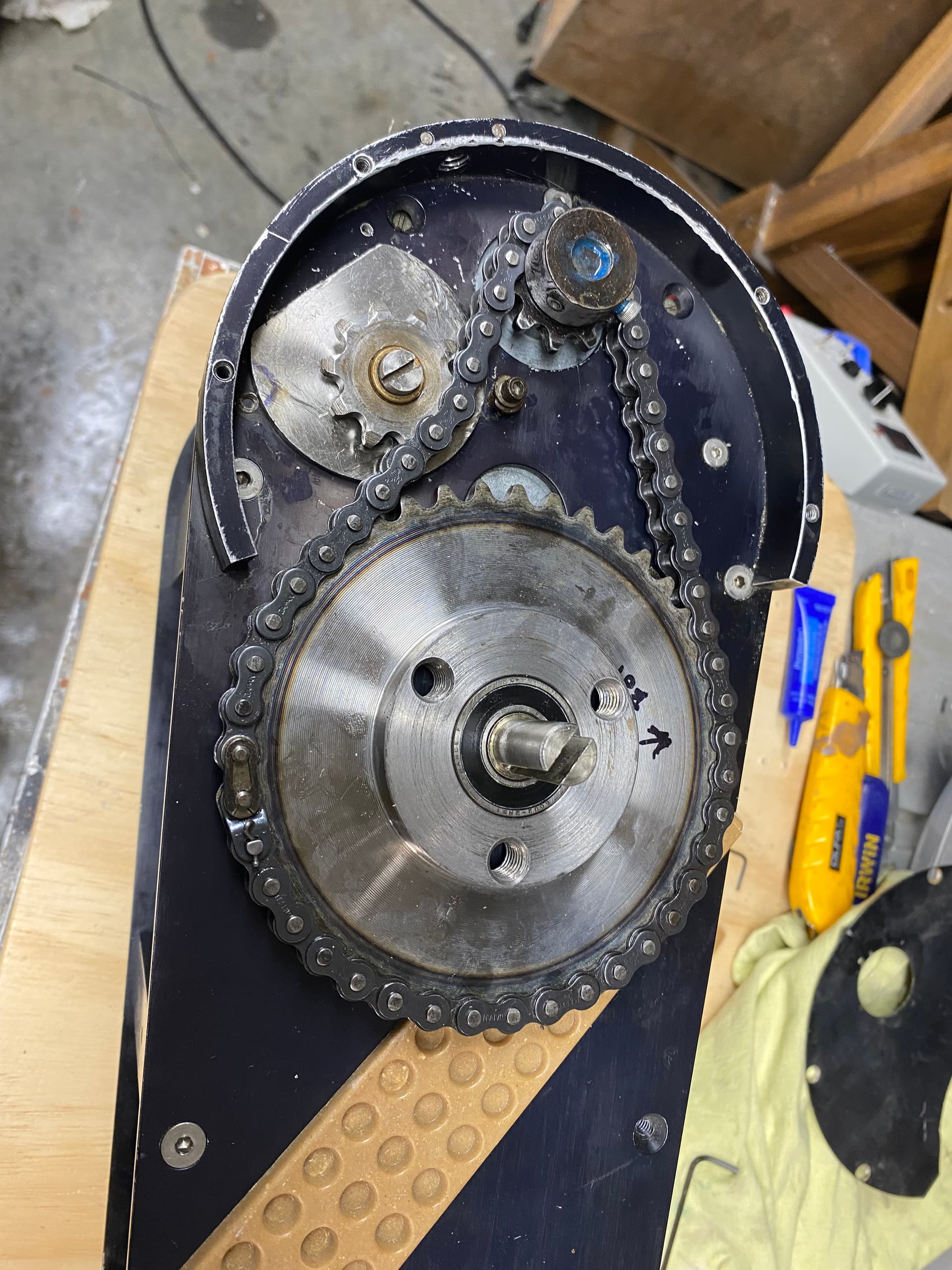
From what I can tell it has been cobbled together with parts from an old robot arm (circa 80s/90s) and misc. motor controlled joints… All the motors seemed to be different and none had any labels to indicate voltage.

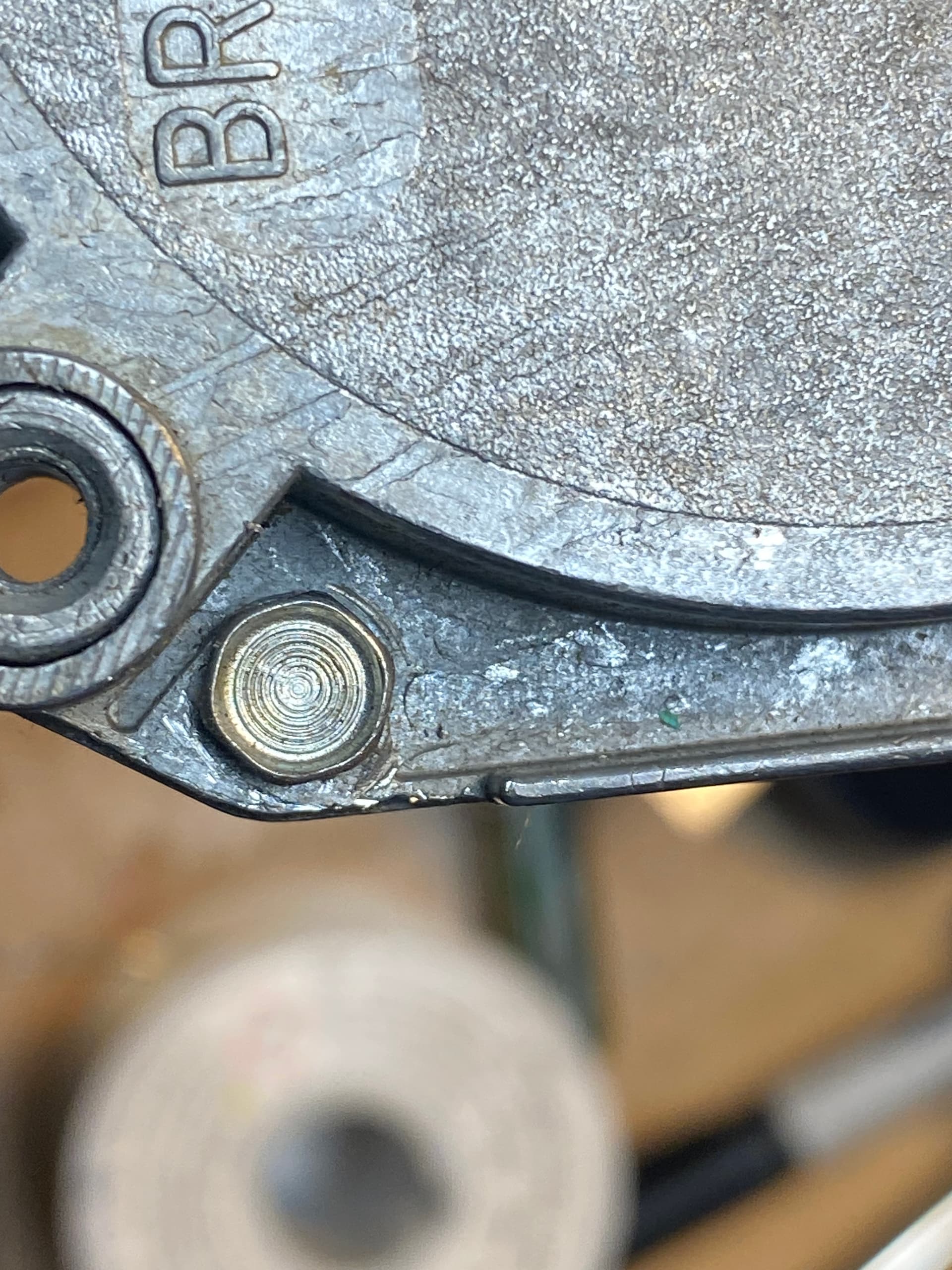
Each joint also had a quadrature position encoder (HEDS-5500) which were still available but really pricey ($80.00 +).

There are 5 motor controlled sections:
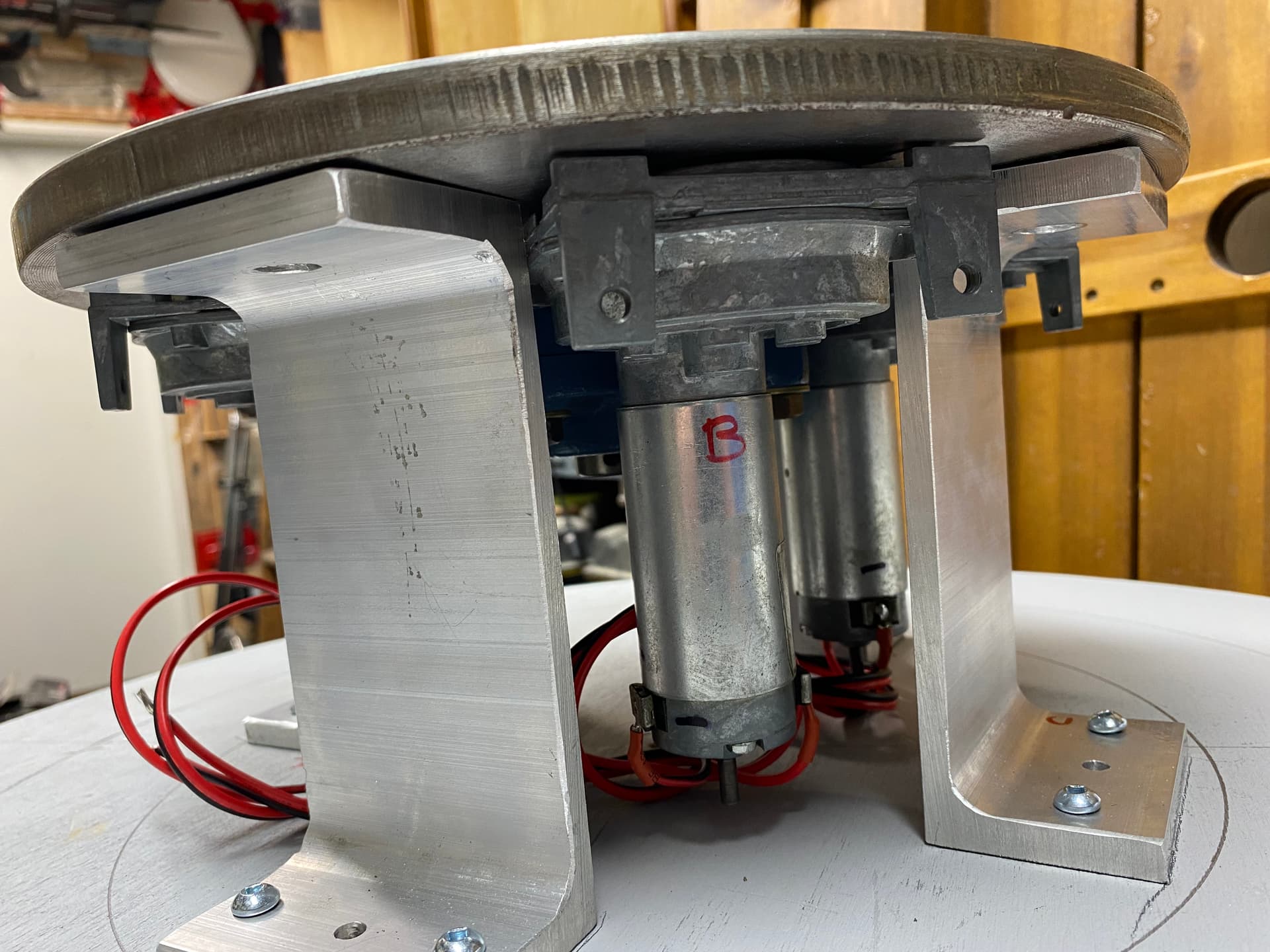
Base Rotation
Base Joint Tilt
Middle Pivot Tilt
Head Pivot
Head Rotation

And 2 servo controlled section:
Horns Pivot
Tongue Movement

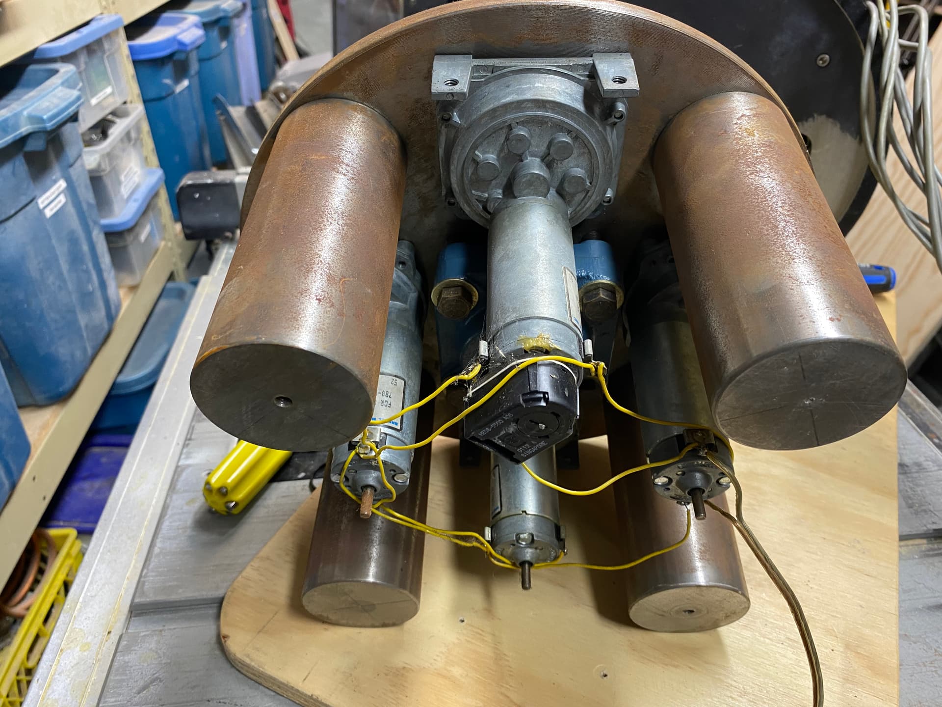
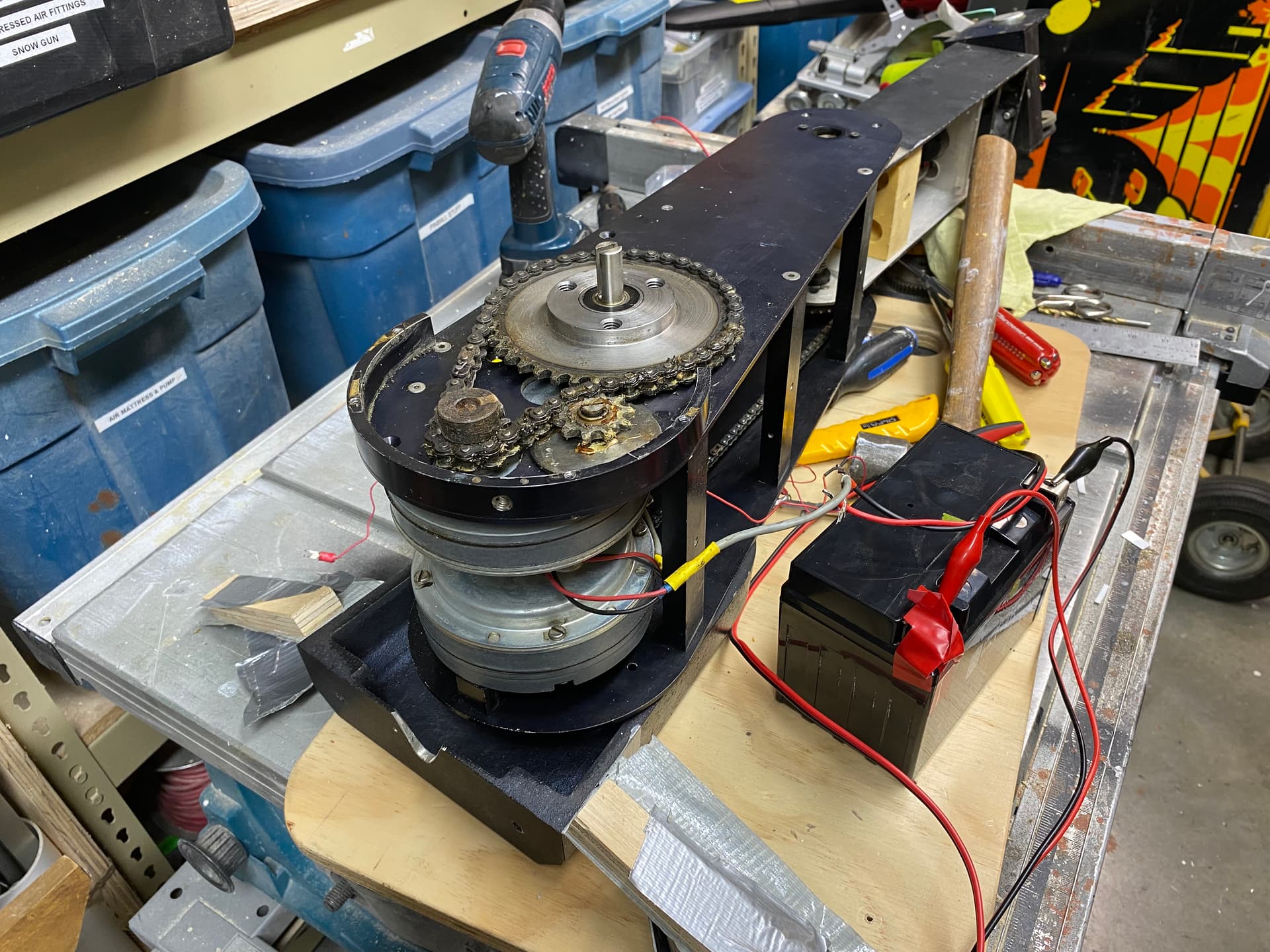
Each motor and encoder had its cable snaked out of the base along with a cable for the servos:

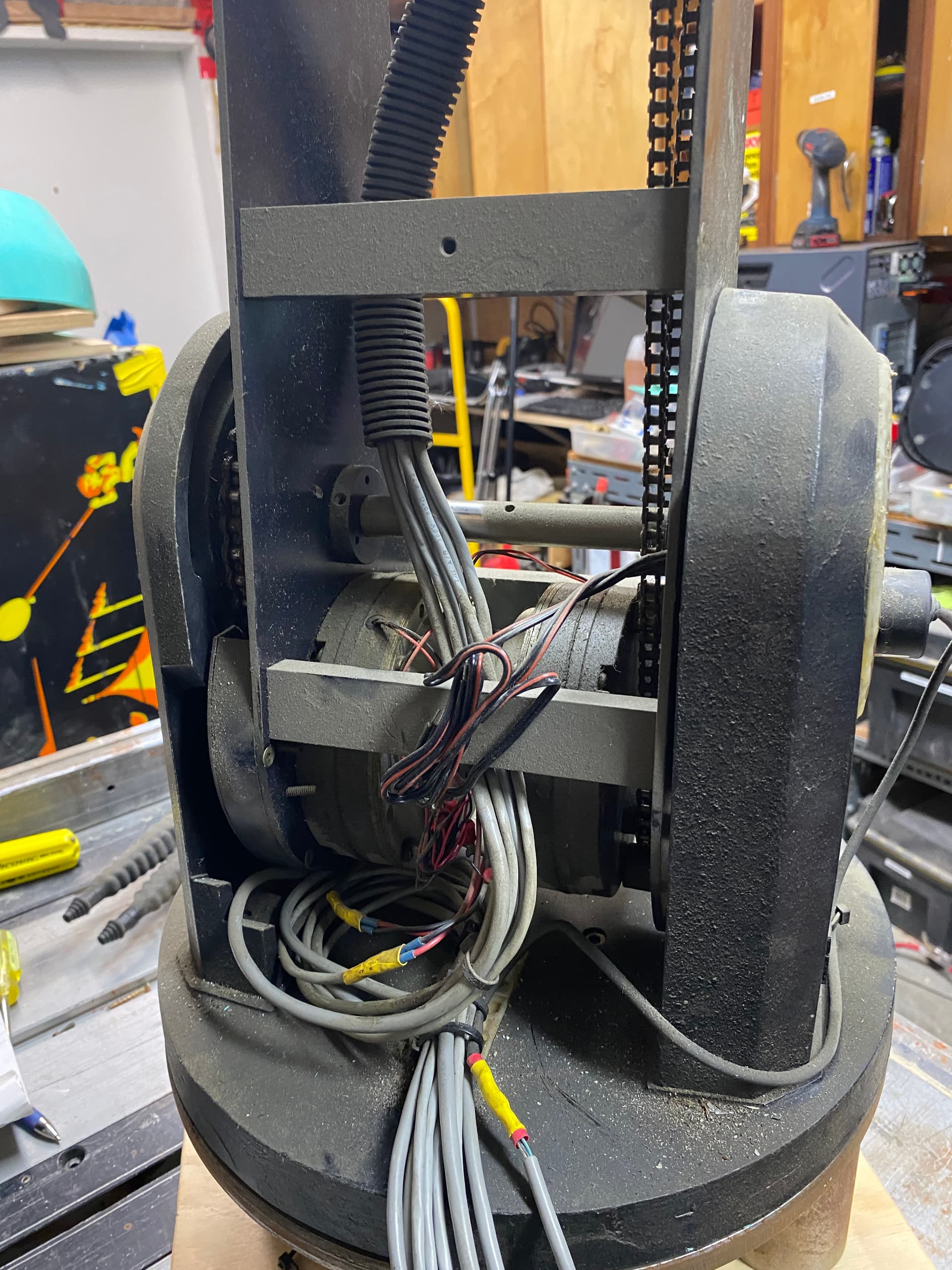
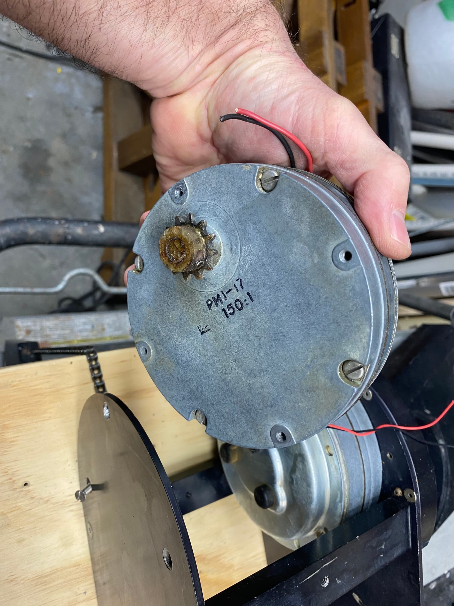
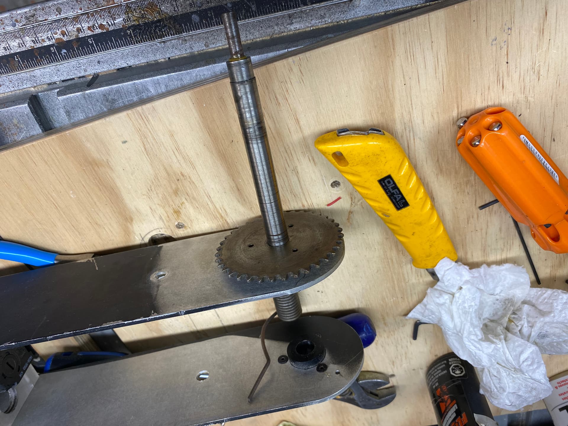
To start I pulled apart the cabling and labelled what cable went to what motor. I then checked each motor for some idea of the spec but had no luck finding anything. There were a few part numbers but had no luck finding out anything.

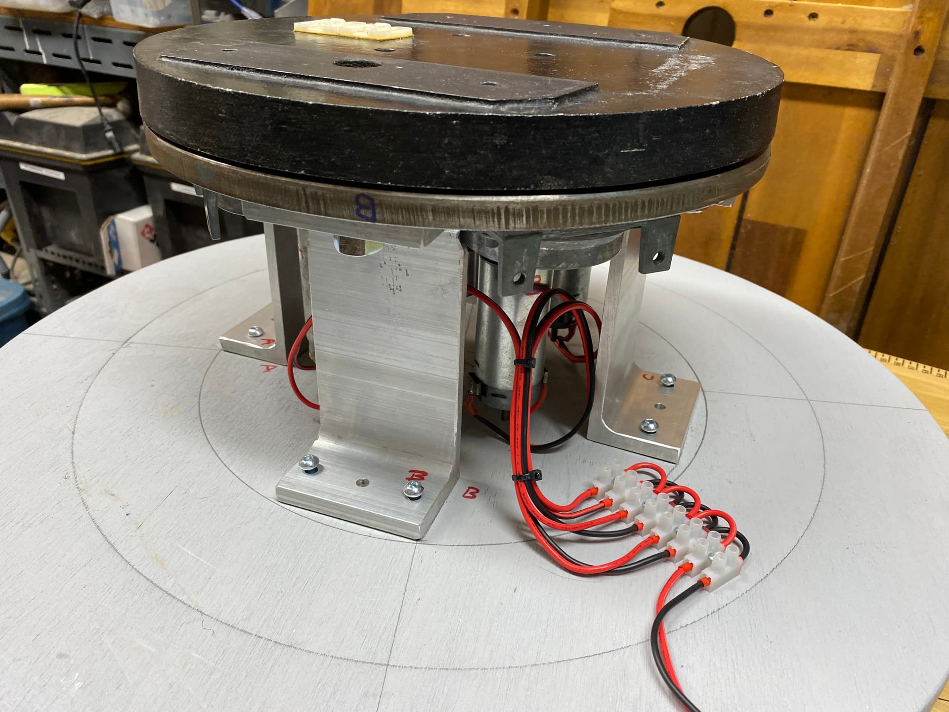
So I decided to Hail Mary it and see what would happen with a quick jolt of 12V DC. To my amazement each of the motors moved and nothing blew up. Got a little braver and determined that each of the motors would move through it’s full range using 12V. I had to be careful not to move any past the physical limits of the mechanism. This was great news as it meant I could easily control the motors with inexpensive easy to obtain H-Bridge driver modules and use PWM to control the speed. (which would allow for easy control using an Arduino).

Next I had to think about position control. Each of the motors joints did have an expensive quadrature encoder but these are only good for relative position. In other words they can tell you how far you have moved from a stating point but cannot tell you where they are in the allowable movement arc. While Eddie didn’t come with any control electronics, he did come with a sort of exoskeleton control arm that seemed to mimick all the joint.

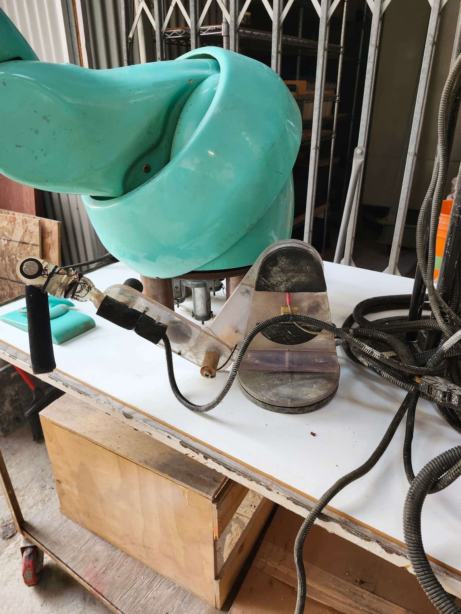
At each joint it had a potentiometer and had a mess of cables that I assume would have led to some sort of controller (same controller all the motor and encoder cables would have gone to). I’m guessing that Eddies’ various joints would have been manually moved to some central positions and then was puppeted using the exoskeleton control. The operator would have had to make sure they did hit any of the mechanical limits which would have been fine for the limited amount of operation needed for the movie or add it was used for.

But this wouldn’t work for animatronic control where I have to limit movement to ensure I don’t rip it apart and need to always know the absolute position of each joint. The joints can easily be moved manually so Eddie could power up in any position, this means I always need to know the absolute position of the parts.

I also had to think about how I wanted to control Eddie. Ideally I wanted to be able to use animatronic control software like Visual Show Automation (VSA). VSA lets you sequence various motor movements with a sound track and there are ways to set this up for stand alone operation. That means Eddie can have various sound tracks created and movement can be choreographed to it. Then any of the sequences can be activated via a switch or whatever desired…

VSA also supports DMX output so this lets you use a host of controllers, lights or whatever you have that supports DMX. And it also means that if Eddies controller uses DMX it can be controlled using any DMX source (and thin can make testing, setup and troubleshooting much easier. However there is no cheap off the shelf solution to allow DMX control of DC motors with absolute positioning. But there are cheap DMX servo controllers (and I have a few) and since 2 of the 7 motors are servos this will immediately solve some of the control challenges.

The DMX servo controller I plan to use is called the Bobcat and it was designed by some Xmas lighting folk back in 2011. It supports 8 servos and 8 constant current LED channels. It has configurable limits for the servo range. Kits and PCBs for these were sold back in 2011 but are no longer available (luckily I have a few kits).

I still had the issue of positional control of the 5 other DC motors. I eventually found this site:

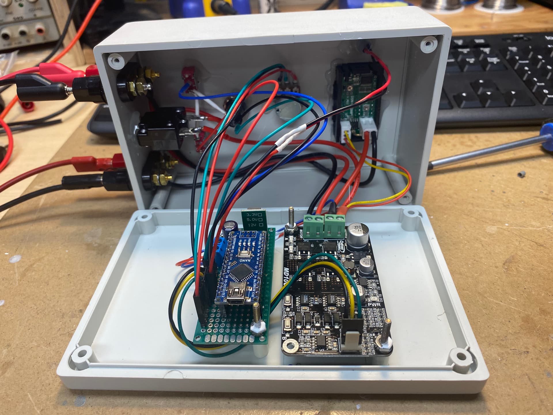
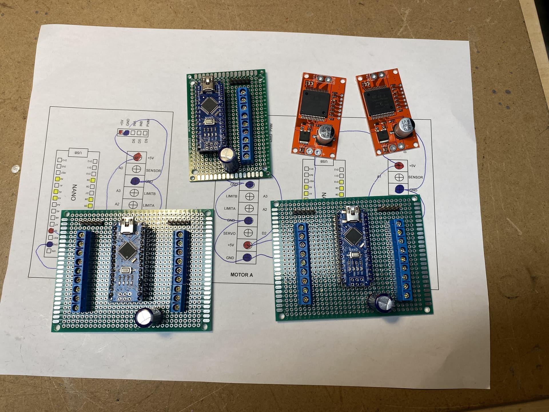
This code will allow you to control a DC motor (using a cheap H-Bridge controller), track it’s position (using an attached potentiometer) using a small micro controller responding to a servo PWN signal). This means I can control each motor from the DMX servo controller. Sounds a bit convoluted but I don’t think I can find a easier (or cheaper) solution. And I may already have most of the parts.

In this code a SAMD21 based Seeduino XIAO is used. These are cheap (less than $8.00 at Digikey). However I am going to see if I can get this working on an Arduino NANO as I have some of them. And since the NANO has 2 pins with interrupt support (needed to for measuring the servo PWM control signal) I’m hopping I can control 2 seperate motors with each NANO.

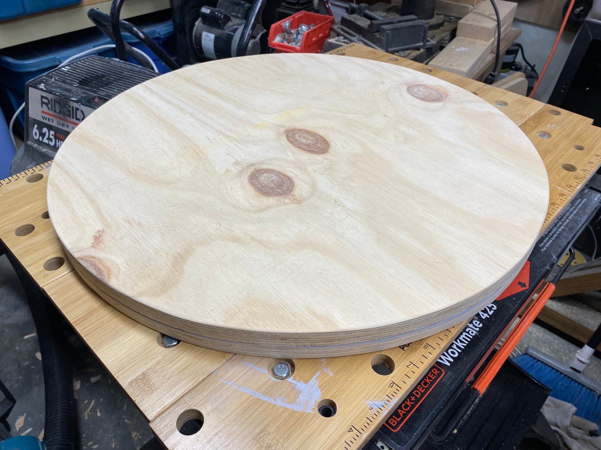
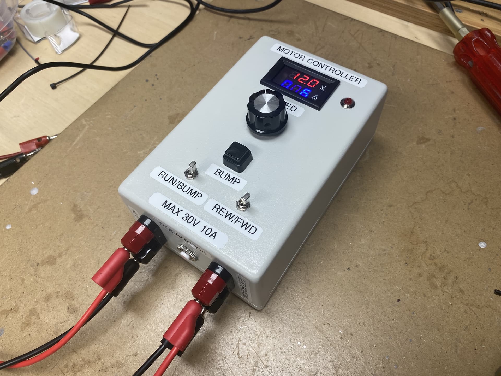
So next I’m working on building a test setup of the controller detailed above. I’ll try with a single motor and if that works I’ll try it with two motor control channels.

8 Likes

To start I removed the arm assembly from the base plate…

Luckily this was pretty easy as it all mounts via a central 1" steel shaft that is held by a heavy duty bearing assembly.

About this time I also decided to try to clean up all the grease/oil/debris/etc that covered everything. I put on some gloves and went over all the parts with rags and paint thinner. Went through a lot of rags (and did it outside in the cold). Then I went over everything again with rags soaked in alcohol and then again with some spray cleaner (this part I did inside in the warmth). This made it much easier to continue the rebuild.

Eddie’s base is made from a 16" disc of 1/2" steel plate with 4 6" lengths of 2-1/2" steel rod…

This weighs a ton and I wanted to try to lighten it up. To start I cut up some 3/4" plywood and glued it together…

Then I went on the hunt for a better (or at least lighter) way to do things. I thought various ways of usign angle and plywood but everything I came up with would impact the location of the motors and the ability to put some sort of position sensor on the central shaft…

The ideal solution (least the best I could come up with) was to replace the 2 1/2" steel rod sections with some lighter weight aluminum and even better would be to use some 6" channel. But not something you find at Home Depot… As luck would have it I had to go out to Burnaby and the Metal Supermarket was close by. They have an off-cut section and turns out they had some lengths of n6" aluminum channel. They charge by the pound for off-cuts (%about %5.00 for aluminum) so a 24" length was $30 and getting four 3" sections cut was another $8.00.

Next I drilled out the bolt holes and filed off the sharp edges

And I had my much lighter supports ready to go…

Next up were the motors that mount on the base plate. There are 4 of them connected in parallel driving gears that mesh with the robotic arm assemble. All the motors worked when I tested them earlier but they were noisy. I disconnected the wiring (which was a bit janky anyways) and removed them for testing. 3 of the 4 seemed OK but 1 of them was making most of the noise and it drew twice the current that the others did… So I decided to pull it apart.

First problem was they used a hex machine screw but it was so close to the gear box body I could not get a nut driver on it…


I ended up using some needle nose pliers (luckily they were not really torqued down) and managed to open the gear box.

All was physically well but the grease was pretty hard and sticky. I carefully pulled it apart (hopefully properly documenting where the various parts went) thinking that the gear trains lack of lubricant was the issue.
Turns out not the case as even with all the gear train removed the motor was still noisy and had the same high current draw. In fact by the end of the testing I could feel the motor shaft binding on it’s bearings so something was gone…

Unfortunately the motor bolts are in a similar position (really close to the motor housing) so my nut driver won’t reach them. I may try grinding a slot (for a screwdriver) or grinding done a nut driver to make it fit.

My thought is that 4 motors is a bit overkill and hopefully I can make do with just three. I plan to take the gear case of each of them apart to clean and replace the grease. If I get the broken one apart I’ll see if it’s viable to lubricate the motors bearings in them also.

Anyways I’m happy I have a base figured out for Eddie and that I lighten him up by a good 30 lbs…

4 Likes

Amazing. Love the base build and all this documentation. Looking forward to seeing what you do next. Are you leaning toward thinking the bearings are shot or that something is wrong with the motor itself on the electrical side?

Decided to sacrifice a nut driver

Managed to grind enough away using a bench mount belt sander to allow it to fit onto the motor bolts

This allowed me to take apart the motor that was making the horrible noise…
Looks like a few issues…

Both ends that ride in the bearing sleeves look like they are worn most likely due to lack of lubrication and age… Can’t replace the sleeve but can add grease…

Commutator is a bit warn but the brushes look OK, may try to clean up commutator with some fine sandpaper though this might make things worse…


It does look like part of the armature is rubbing on the stator magnets… Perhaps the bearing wearing out is allowing the armature to wobble or it does look like the magnet was chipped and perhaps a part got stuck or ??

I’ll try a combination of greasing the bearings, filing the armature and perhaps touching up the commutator… And then hoping I can get it all back together… At best I’ll have a spare working motor… At worse I’ll have some spare gears and the knowledge of not pullign apart the working motors (but I will still clean and repack the gear trains in them)

2 Likes

Turns out the issue was even simpler…
One of magnets has come loose from the housing…


They are just glued in…
May try using some epoxy…
Or may just consider this motor toast…
Even with some grease on the bearing it still doesn’t rotate very smoothly so may not be worth saving…

4 Likes

The grease in the motors gear boxes is kinda tar like so I decided to clean them out and replace the grease…

Used some solvent and a good brushing.

And got the gears cleaned up…

And hopefully put them back in the right places…

Once I was sure the gear train was working I pulled it apart and packed it with new grease…

While it’s hard to quantify the effect of cleaning and re-greasing things I did notice (at least in the one motor I have done so far) about a 15-20% drop in no load current draw…

One motor down and two more to go…

5 Likes

Finished re-greasing the 3 working motors and soldered on some better wires…

Mounted them on the base plate…

And discovered my aluminum mounts were a bit too wide…

So gotta narrow down the alum channel sections by a good 1/4"…

2 Likes

will it breath fire?

Perhaps for a short time the first time I turn on the power if I have screwed up…

I do want to at least get a bunch of fire’ish looking LEDs in the mouth to give the look of some fire…
@Weas3l was mentioning that he knew of some tiny smoke machines though I don’t know if there will be room…

I mean what’s a dragon without fire…

Though it could be Eddie the “No Greenhouse Gases” Dragon who doesn’t breath fire…

5 Likes

LOL! cant wait to here his back story

1 Like

I have seen some hand held atmospheric foggers used in Indie film shoots, they have about 50 shots of fog before needing refilling. In practice, a fogger is just a heat coil wrapped around a tube connected to a pump and glycol reservoir… So in theory one could figure out how small the heat coil could be and route a hose up the arm to a nozzle/coil/rgbled setup to create plumes of coloured smoke on command ~^.^~

1 Like

I’ve seen cheapo AliExpress vape pens modified into a very small fogger in costumes. Same principle, just missing a fan or puff of compressed air to blow it instead of just making a cloud.

MicroFogger 5 Pro – Vosentech is the brand I’ve seen used in my venue. It was really impressive in it’s ability to heat quickly, produce a big hit of smoke, and be refilled really quickly. I don’t do a lot of work that requires it as a personal tool, bit I do want one juuuust in case :rofl:

2 Likes

Perhaps we are thinking the wrong way for ‘breathing smoke or fire’. A) partially because you run the risk of setting off fire sensors b) not all people are comfortable around atmospheric particles from a smoke machine/hazer and c) there is a potential for spillage or reside buildup from a fog machine nozzle.

Maybe if there is a way to use a humidifier or atomizer somehow to release a large cloud of water vapour it may simulate smoke or flame, not fill the space with atomized heated glycol, and not set off the fire alarms?

1 Like

Good idea…
I actually have a few ultrasonic misting modules so this may be doable…

2 Likes

Alright…
Got the motors installed and wired up…
Installed the 3 gears…


Luckily it was easy to remove the base from the robotic arm assembly so I could mount it on the motors and confirm operation. There was enough play that it easily slide into place…
Fire up the motors and all worked fine…

It seems pretty powerful so think I can live without the 4th motor in place…

Above is the base with the bottom cover in place…
Eddie has feet…

Next I needed to look at the robotic arm mechanisms…

Getting base off was easy and then each side section just slide off it`s bearings…
One side had some limit switches that were broken and not used…

I pulled them off and greased up the bearing (which was pretty dry)

The other side had the gear and chain assembly for the tilt mechanism and it was pretty interesting


There is a home made chain tensioner held in place with a piece of wood and bunches on machine screws…
One of the chain pins is held in place with a bent finishing nail!!
The worst part though is that all the grease is gummed up (like really hard toffee in places) so I`m going to rip it all out to clean up… Here is a better view of it all

And a video of it in action

3 Likes

Getting the chain and tensioner apart was no issue but the sprocket on the motor shaft seemed to be stuck tight…

I used some penetratingly oil and lots of leverage but barely moved it…
It almost seemed like they glued it together with epoxy or something (not like Loctite) because I chipped away lots on top of the shaft… I have a small gear puller but I didn`t have the clearance under the gear for it until I moved it a bit. Used a combination of pliers, prybar, hammer, and screwdrivers and finally moved it enough to get the gear puller on it…

And yes the bolt on the left side of the puller is missing a nut (dropped it and couldn’t find it but still wanted to pull the gear) and did pop out just after I started cranking it down after I took this picture… I did get it off without hopefully damaging the motor…

Used more solvent to clean up the bits…

Once I clean the motor gear I`ll take a Dremel and use a small wire wheel brush to clean up the motor shaft and the inside of the gear so it will go back together without having to hammer the gear on…

3 Likes

Once I had the bottom gear and chain removed I decided to remove the gear and chains for the upper joint (the elbow in robotics talk sorta)

This required pulling out one of the pancake style motors…

They had no markings except for a manufacturer PMI and a patent number
Which lead to this:

https://patents.google.com/patent/US3144574A/en

But no real information… I contemplated opening one up to replace the grease in the gear box but didn`t want to risk ruining one…

Got it all apart and cleaned up then decide that I really should try to lubricate the bearings in the elbow joint…

So I pulled it apart also…

Hopefully will remember how it all went together…

Eddies has 10 DC motors and all have gears or chain assemblies that must be orientated correctly to get back together. I was getting tired of using test leads connected to a battery and quickly touching the motor leads to position thing…

Decided I wanted some sort of motor test jig…

To start I got a cheap DC motor controller but found it was crap… Even at it`s lowest speed the motor would still turn… Decided to use an Arduino NANO and a PWM motor control board…

Cobbled together some code and rigged it so it had a PWM speed control, Forward/Reverse toggle and the ability to use a bump switch instead of continuously running (handy to get the gears into the needed position). Also added a volt and amp meter and a circuit breaker…

Excuse the sideways video…

2 Likes

I have started testing the PID based servo control for the DC motors. This essentially turns any motor into a RC style servo. It takes the 1000-2000us PWM pulse from a servo controller and moves the DC motor as required based on feedback from an attached pot. It is all based on info I found on this site though I`m using a NANO instead of a XIAO controller:

I cobbled some stuff together to at least see if it works and it does…

I`m sending the PWM servo signal from a little servo tester and the NANO driven motor controller is moving the motor to match. I have the pot coupled to the motor shaft with some rubber hose and the pot is held in place by wire and a weight so all in all a pretty janky test setup…

But it works so Eddie`s motors are one step closer to being controlled…

Gotta set things up a bit better on the test board and then see if I can drive 2 seperate motors with seperate PWM servo inputs. As the NANO only has two IRQ inputs (and that is needed for the measuring the servo pulse) I am limited to 2 motor channels per NANO…

I also plan to use AS5600 hall effect encoders instead of the potentiometers for determining the motor shaft positions…

4 Likes

Spent a while cleaning up the remaining parts of the gear train in the base…
Lots of old hardened grease to remove…
It`s amazing how much guck is in a chain…
And then was able to start putting the robotic base drive train back together…

It certainly runs smoother…

Hoping I remembered all the parts…

And then got it mounted on the new base…

So now the 3 main motors and gear assemblies have been rebuilt or at least re-greased…
Here are the various bits in motion…

Now its time to make the motor controller boards. I had originally thought of putting all the control boards in an external box but now think I can fit it all in Eddies housings… May not have enough room for the 12V power supply but that will depend on how big it ends up being. I`ll need a power supply with enough capacity to allow all the motors to move at the same time… Here is how far I have got. One of the boards will be a single motor and mount in the base. The other two boards will each do two motors and be mounted in the arms. Each motor will also need a H Bridge controller. I am using some VNH2SP30 based ones I got a few years back.

3 Likes