Eddie the Animatronic Dragon

I’ve spent a bit of time trying to sleuth out this thing’s back story… Could we get a close-up of the EXCALIBUR logo? :slight_smile:

Neural Network Servo Control of a Robot Manipulator Joint in Real-time [1991]:

Douglas M. Charney and Gary M. Josh, Neural Systems Incorporated
Empirical results are presented for a real-time experiment where a feedforward neural network is
used to replace an existing PD servo controller and trained on-line in real-time using a
performance measure to control positioning of a robot manipulator joint. The optimized neural
network controller is tested on-line as both a fixed and adaptive controller, with step and ramp
input commands, under different joint loading conditions and the results are compared to the
existing PD controller.
[…]
Figure 2 mentions an “Excalibur Robot upper-rotate joint”:

1 Like

From a Google cached copy of UBC EngPhys “Pictures and Outlines of Past Projects” page which is really hard to find anywhere else:

4 Likes

Aha! The “RSI” in there is the final clue! Excalibur was a product of Robotic Systems International based in Sidney BC in ~1986.

I’ve messaged someone who was a software engineer there in the 80s, and here’s another guy’s description of his time there:

Designed and developed human/machine interfaces for robotic manipulators that were mounted on remotely operated submersible vehicles (ROVs) used in offshore oil drilling. Set up and managed a Unix-based C programming development environment with cross-compilation for robot controllers running OS/9. Managed team of four software developers. Applied advanced software project management techniques developed by Prof. David Parnas at UVic. Developed automatic fault-tree analysis method for incorporating exception handling in manipulator control systems. Documented manufacturing processes. Developed calibration procedure for company’s Hall-effect joint position sensors. Developed a high-level programming language and optimized motion control for shop-type manufacturing robots.

1 Like

I will get a better pic when I get home…

I don’t think we need it anymore, if my sleuthing has been successful, but thanks! :slight_smile:

A partial snippet from the 1986/03/31 issue of the Vancouver Sun:

2 Likes

So nice to know that Eddie was born in Sydney BC in the late 80’s…
A local dragon…

1 Like

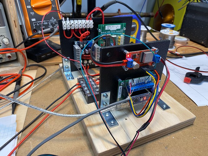
Put together the 5V power supply, DMX servo controller and first motor control board…

Have been playing with the NANO’s PWM frequency as the stock 490 Hz makes an unpleasant whine with my test motor. I bumped it up to 3921 Hz and it’s way better but still noisy… I tried going to 31,372 Hz but for some reason it make the PID really unstable…

I’ll try sticking with the 3.9kHz PWM rate and mebbe it won’t be as noticeable in the actually robot (compared to my test motor). I’m using the NANO as I have a bunch of them and the motor controller boards (which I also have a bunch of) need 5v logic (which the NANO has)…

Next come figuring out the AS5600 hall effect rotary sensors. While they have a I2C output they can also be set to output a simple 0-5V signal corresponding to the 360 turn of a magnet. The web seems to have contradicting info on how this is setup so we will see…

2 Likes

That power assembly is… It’s… Its beautiful! I am so envious of it.

In order to control Eddie’s various motor controlled joints I need some sort of way to detect the absolute position and supply that information to my controller. While a potentiometer is the simplest there is the issue of mechanically coupling it to the moving axis and the fact that most pots are not designed for large amounts of rotations (although essentially ever RC style servo has a pot inside for positional feedback).

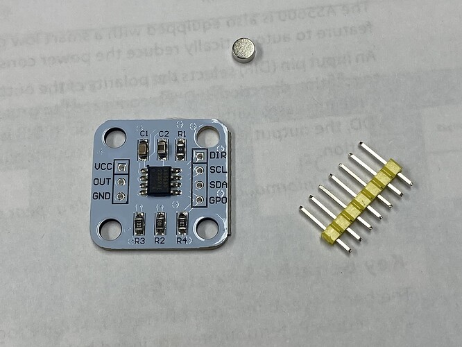
I decided to go with the hall effect AS5600 modules as they are cheap and plentiful on AliExpress. These come with a diametric magnetized magnet and provide a absolute value related to the rotation of the magnet.

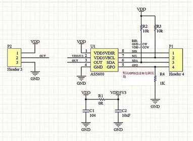
There are small while they have a I2C interface they also output a 0-5V analog signal so this is perfect for any control expecting a signal from a pot. However reading up about them found lots of conflicting information about getting them to work properly. In fact it was tough to even find an accurate schematic but this matches the modules I have:

AS5600 Module Schematic

The information below is for getting these modules to output a 0-5V analog value related to the 360 degree position of the magnet. You need to make a few changes…

Power
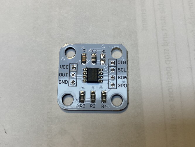
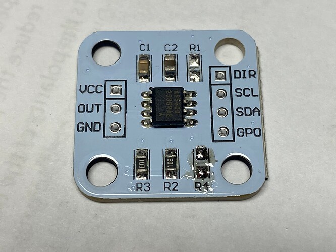
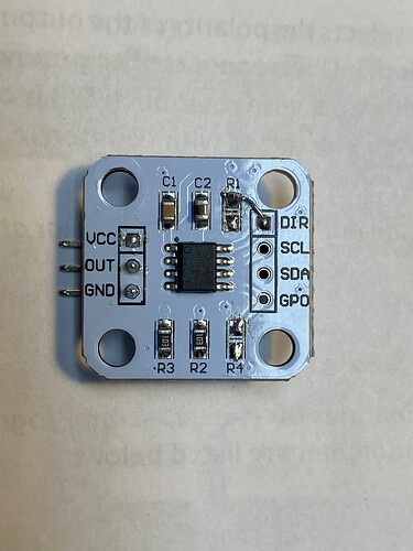
The AS5600 module can run off 3.3V or 5V. As they come, they are setup for 3.3V. If you want to run them off 5.0V then you need to remove R1. R1 is a zero value resistor that bypasses the internal 3.3V regulator for 5V operation. I used a soldering iron to heat up and pick off R1:

Analog Out
These modules have R4 on the GPO pin and this doesn’t allow the analog output. You need to remove R4.(or you can connect the GPO pin to +V but removing R4 is easier:

Direction
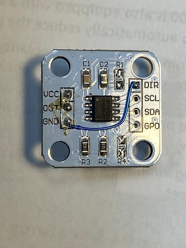
The DIR pin controls the output in relation to the rotation of the magnet. If it is connected to GND then the output increases as you turn the magnet clock wise. If it connected to +V then the output decreases as you turn the magnet clockwise. These modules leave this pin floating but all the manufactures info states you must use one or the other. I suspect the original designers of this module meant the R4 pull down for the DIR pin and this mistake has just been repeated by everyone making copies. Below you can see how I wired up a jumper for each of the directions:

I got the +5V from the R1 pad…

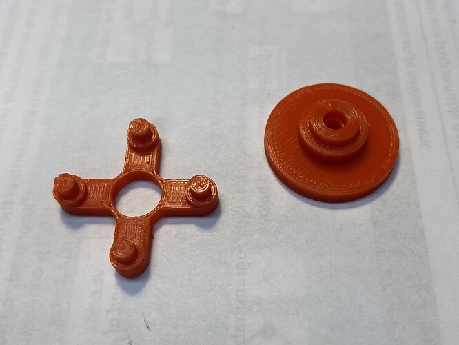
Once I had the wiring figured out I wanted to do some testing so I can figure out how to orient and mount the magnet. I found this on Thingiverse:

But the hole for the magnet on the wheel was too large so I also grabbed this file:

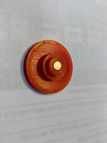
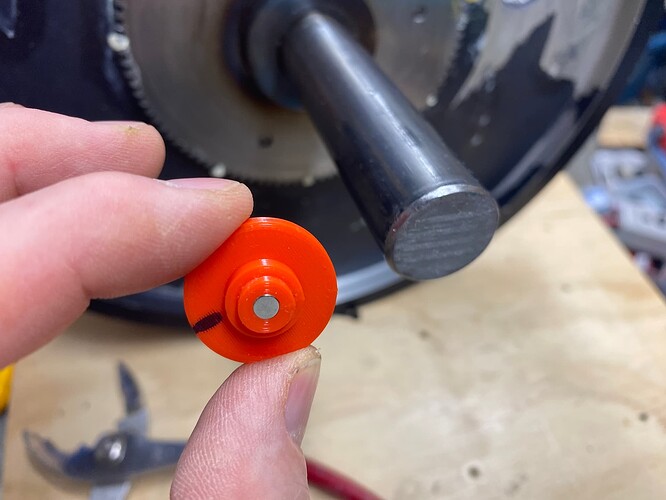
And I ended up with this:

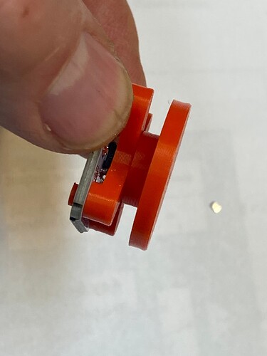
The magnet mounts like this:

And the whole thing goes together like this:

This allowed me to hook it up to a power supply and meter to see the output change as I rotated the wheel. It also lets me figure out where the output goes from the full 5V to 0V as it goes from 359 degrees to 0. You will need to know this to ensure the magnet and encoder are mounted in a way to give you a smooth voltage transition between the limits of movement on the axis you are monitoring.

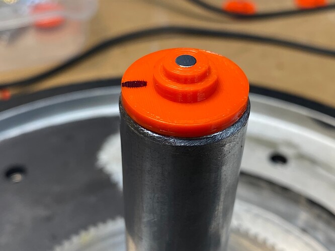
For Eddie I’m going to start with the base rotation axis. My plan is to mount a magnet to the bottom of the main shaft and mount the encoder module underneath it. The magnet wheel holder from the 3d print is actually the right diameter so I may just glue it onto the bottom of the shaft with some epoxy.

2 Likes

Was thinking of using hot glue for mounting some of the magnets but turns out the neodymium magnets don’t like heat:

1 Like

I epoxy glued the 3D printed magnetic holder to the bottom of the shaft. I had planned to design some sort of holder but this worked out perfectly as it is a slightly smaller diameter so it allows it to slide through the bearing. I just had to make sure the magnet was oriented correctly…

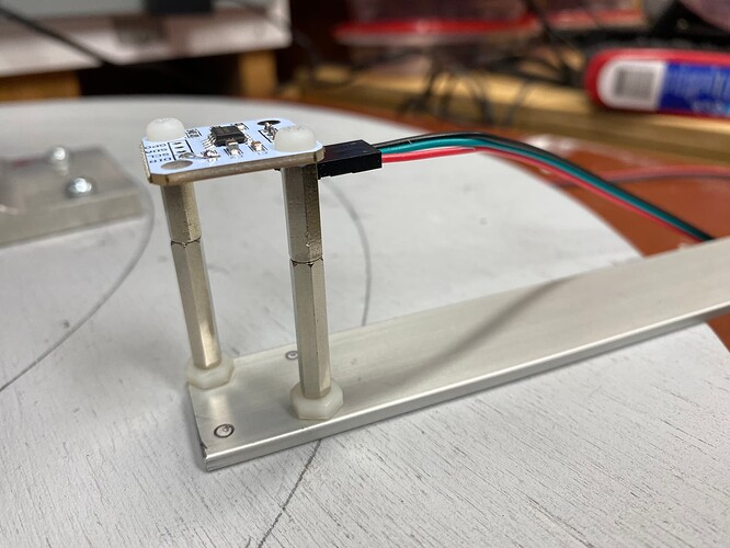
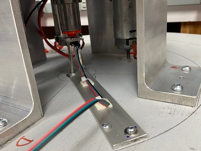
I then rigged up a holder for the AS5600 encoder board…

And mounted it under the bottom of the shaft…

Tested it out and got a voltage output from 0 to 5V as the shaft turned through out it’s 360 degrees…
Next I wired up the Arduino controller and connected it all up…
Though I plan to use a DMX servo controller I decided to test with a RC transmitter/receiver combo…

It works somewhat better than expected!!!
A few things:

  • With the usage limitations of the NANO I only have 3 PWM frequency options. 490Hz & 3190Hz are both too noisy so I’m usign the 31,000Hz. Previously I had issues with this PWM frequency but it now seems to be fine (and quiet)…
  • I added some bounds checking for the various values as I causes a few issues while unplugging/plugging in the servo controller. This wouldn’t happen in normal operation but still figured it was wise. I need to improve on this to hit the various scenarios with the PWM input doing strange things when the RC transmitter is shut off, the RC receiver powered down, etc…
  • I do need to add both an emergency stop button and limit switches to stop things when the PID software runs amuck… I do have two input pins wired in on the controller boards so this will be simple. I’m going to look around for more examples of such position control code.
  • Though it didn’t seem to ever happen in previous testing I now get a noticeable “clunk” when the motors are moving fast back and forth. There are 3 motors with gears that mesh with a gear on the base. Each has a fair bit of play so I didn’t seem to need to align anything but perhaps a gear is out of alignment. I discovered that the base has more than enough torque with the 3 motors ( hence the need now for an emergency stop ) so I may also remove one so just let 2 motors fight it out… Or I may just go with 1 motors as the less torque the better as long as it moves the head…

Anyways gonna work on the code a bit and get e-stop and limit switches in place. Then the code (and controllers) should be “cut & paste” easy to replicate for the remaining 4 motors…

And eventually Eddie will be alive!!!
test

2 Likes

So the led nerds in me needs to ask, are the horns transparent enough to cram some ws2812s in em, same question for the eyes. The thought of giving emotional colour and tasteful horn rainbows popped up looking at the above image :slight_smile:

Unfortunately the horns are a solid black rubber and the eyes are solid black plastic with a shiny metal discs for eyes…

But there will be LEDs… Lots of LEDs…

Sounds to me like the horns are a good candidate to be archived in silicone, and the eyes vacuum cast and for posterity to me :wink:

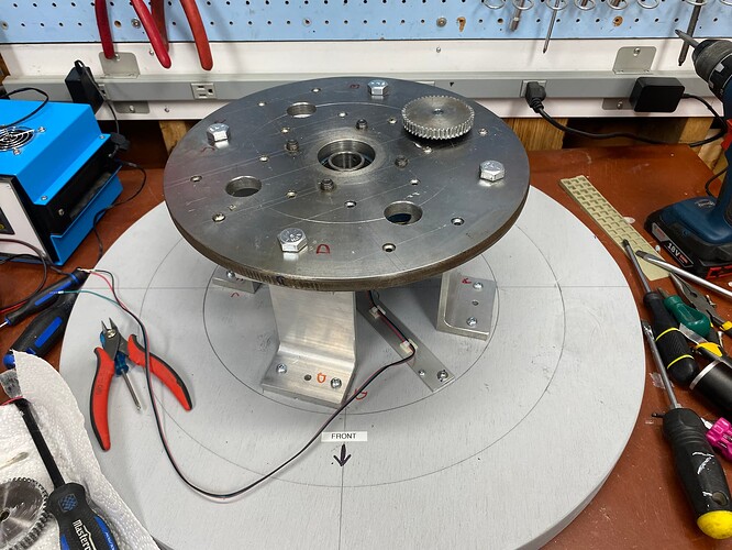
So I pulled the base apart (for the umpteenth time) and removed 2 of the motors leaving just one…

Put everything back together and it seems that the single motor is more than enough to move the base and it still seems to have plenty of torque. There is more backlash than with the multiple motors (and what dragon doesn’t have backlash) but the random clunking seems to be gone… And I have 2 spare motors…

And here is a video of the base being control via wired DMX from a little lighting console:

My DMX servo controller has 8 servo outputs (I need 7 in total, 5 for the various axis motors and 2 more for the horn and mouth servos). It also has 8 constant current LED output channels…

With this system I can use wired DMX so I can do all the animation sequencing using Visual Show Automation (VSA) but can also puppet it using a RC controller.

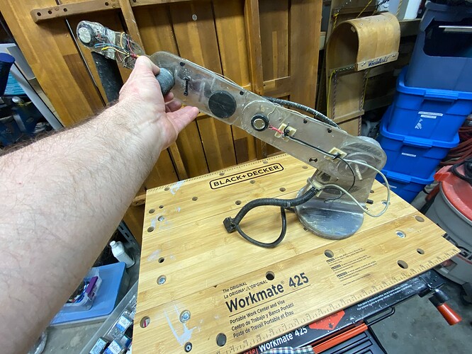
Eddie also came with a mechanical replica of his movements with a pot for each axis. It’s in really rough shape but I may be able to use it to help record the desired movement. The version of VSA I have only supports recording 4 channels but they do have a 16 channel version.

All this experimenting has taught me that I do need an emergency stop system (I have bashed the back wall a few times and had Eddie come pretty close to tossing himself off my bench)…

At this point I’m planning on a few layers of protection:

  1. Emergency Power Off switch on Power Supply. I don’t think I will have room for the required power supply in Eddie so I plan to have an external box to house it. I will add a big EPO switch on the case. It will have to be manually reset to power up Eddie

  2. Emergency Power Off switch on Eddie. I will also mount a EPO switch on the plywood base so I can easily reach it while working on it. Once the base cover goes on I may mount an EPO on Eddies body…

  3. Limit Switches - I’m going to install hardware limit switches on each axis. The software limits of the servo motor code should keep the range within the mechanical limits but I’ll add little limit switch that the code will check and if they are tripped it will go into a shutdown loop required a rest to start again.

  4. Motor Fuses - Once I get an idea of the various motor current needs I will fuse each motor (or better still use a breaker). This way if the software goes wiggy and a motor is pushed to a hard stop it will blow the fuse…

3 Likes

Had an interesting bit of troubleshooting…
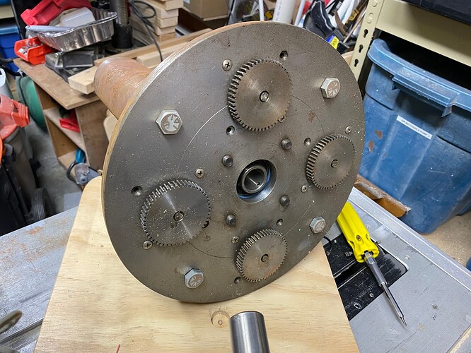
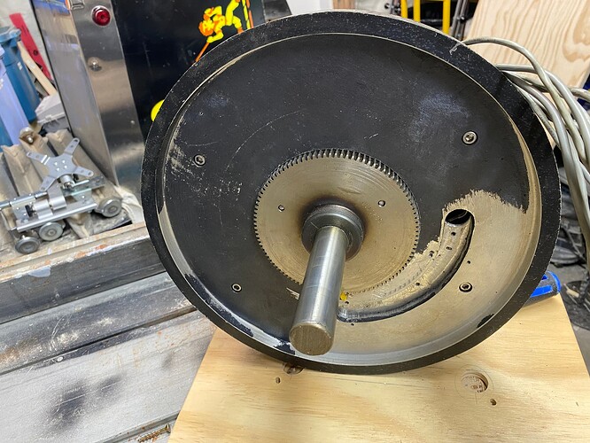
The base originally had 4 motors, each with a gear that connected to a gear on the central shaft…


One of the motors was bad so I ran things with just 3 motors…
Each of the motors had a fair bit of play in the gear train so no fancy alignment was needed to get the central gear shaft assembly put in place…

I setup the motor controller (using the RC servo signal driven Arduino NANO driving a H Bridge driver) and all seemed ok except that every once and a while it would seem the drive train would shudder with a big clunk…

I thought this may be due to misalignment of the various motor gears and really even 3 motors was overkill as there was more than enough torque…

So I needed up going with a single motor. This seemed to have more than enough torque and would avoid any issues with the gear train. This seemed to solve the issue until it didn’t. I was still getting the occasional shudder and clunk… This would happen randomly as I panned the base back and forth…

Lucky for me the motor driver board has LED indicators for direction. I finally noticed that when got the cluck and shudder that the LED for the opposite direction would flash ever so briefly… So something was sending bad motor control signals…

First I thought it may be the DMX lighting panel I was using. I thought it may be sending bad data at times. Moved it to a PC driven DMX driver and although it wasn’t happening as often I still got the odd clunk…

I then setup the NANO code to print out the variables in real time. What I did notice was that somewhat randomly, the variable for the PWM input would go nuts (but just for a 20-60 milliseconds). I then used the Arduinos IDE Serial Plotter function to graph the variables in real-time and confirmed this.

Now I thought it may be the code but it’s petty simple and uses an example I found on the web that no one else complains about. So I hoped it wasn’t the code.

Then on a whim I disconnected the motor and ran the test. Now I had no issue what so ever. I then realized that it may be noise from the DC motor affecting the system. I had long wires running to the motor right next to long wires connection the RC PWM input on the NANO. I separated the wires and the issue seemed to go away. I moved them closer together and the problem appeared and was much worse…

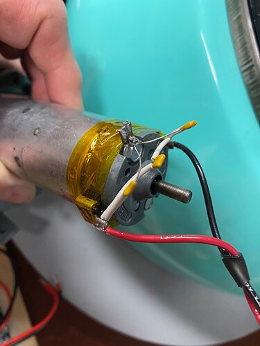
So turns out it was noise from the DC brushed motors which are pretty old and probably act as a pretty good spark-gap transmitter. A better motor would help but I only have what I have…

So spent a bit of time researching and are going with this:

  1. Sticking some capacitors across the motor terminals
  2. Using twisted pair wired for power supply
  3. Keeping the motor leads as short as possible
  4. Using shielded cable for the various signal runs

My plan is to have the AC power supply (a switching 12V 20A supply) in a remote box and may run an earth ground with the power leads to ground the metal motor cases. I’m hoping that this larger motor in the base is the most noisy one and that the smaller motors in the arm don’t make as much noise. But I have re-designed the layout of the remaining controller boards to keep the motor and power leads as far away from the signal leads as possible…

2 Likes

You could also try adding a ferrite bead to the wires to suppress motor noise. Put them as close to the affected input(s) as you can reasonably manage. There is a parts bin of ferrites somewhere in the electronics area at the space.

1 Like

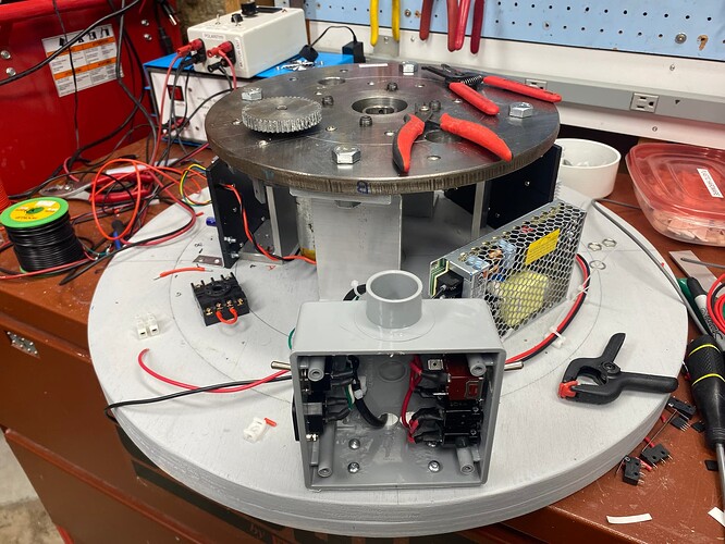
Since long wires from the motors will cause problems I revamped my design to do away with the remote power supply. None of the 12V power supplies I had would fit in the space so ordered one from Digikey and for some reason it took almost a week even though it was a in stock item…

Anyways working on fitting everything thing in the base. The PVC electrical box will house the 120V AC input and power switch. Also adding a seperate motor power switch and some circuit breakers for the motor feeds. And decided to use a relay with the emergency power off switches to avoid having to run the full motor current through the EPO switch.

I have added caps for the motors, twisted cabling for the drivers and will try to seperate the motor wiring from the data wiring along with grounding the frame and using shielded cable for the data lines. Hopefully this will end the data corruption I was getting in the motor driver servo inputs. Once I get the base together I’ll do another round of testing and hopefully be able to start working on the motors in the neck…

3 Likes

Ok…
I have wired things back up and have the base pan motor control working as I wanted…
Proper cabling and filter caps seems to have solved the intermittent glitches I was getting before…

Here is a quick video of the base in operation. It is being driven by a DMX signal from a test routine in VSA. You can see the VSA window on the computer screen at the end (along with a serial plotter view of the variables from the Arduino IDE)

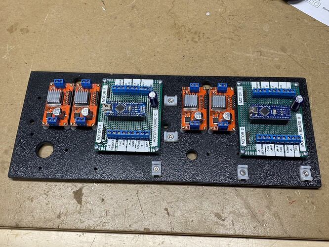
Now I have to complete the wiring of the 4 motors controller that will mount in the arm…

4 Likes