Frackkkk

Discovered the hard way that Eddies body needs a bit more clearance to fit over the controller board I made…
Back to the drawing board…
Frackkkk
Discovered the hard way that Eddies body needs a bit more clearance to fit over the controller board I made…
Back to the drawing board…
I looked at various options and decided cutting a part off the fiberglass body piece was going to be the easiest solution. I figured I can easily re-attached the cut off part. I marked off where I wanted to cut with masking tape and then used a Dremel tool with a cut off blade…
It cut pretty easily and didn’t seem to chip the finish much…
You will notice a hole on the top of the grey plastic box used to mount the power switches. This is for the umbilical of various wires to the moving part of Eddie. But the mounting of the emergency power off switch kinda blocked the path for the wiring. I did a little re-work and mounted the EPO switch on the front. This probably makes it more usable and frees up room for the cabling.
I mounted the controller board and started with the power and signaling cabling for the first 2 motors…
Next I have to rig up position sensors for each of the motors and program the NANOs. The code should be easy as it is just a copy of the first controller but these controllers drive 2 seperate motors rather than just the single motor used in the base.
Finally got off my butt and cleaned up the code…
Added a couple safety features:
Limit Switch Inputs - If either triggered will stop and shut down motors
Sensor Value Checking - If rotation sensor value is out of bounds it will stop and shut down motors
Neither will help if the NANO goes south but then hopefully the motor driver thermal cutout and/or circuit breaker will come into play if the mechanism inadvertently hits a physical limit
And I have the E-Stop button that shuts down all power to the motors…
Don’t want Eddie killing anyone…
…not anymore
Or not yet…
IT WAS NEVER PROVEN! THEY SLIPPED! NO ONE READ THE WARNING SIGNS!
you eat one stray tourist in a sleep deprived hallucination DECADES AGO and it’s all that anyone remembers…
So the motor driver for the base works fine. Its a NANO driving a single VNH2SP30 motor driver.
Its load is minimal as it is just panning the base and the driver barely gets warm…
The next two motors are in bottom of the arms and move the first two joints (shoulder and elbow in robotics talk apparently). Since I wanted to avoid running long wires for the noisily motors I figured I could mount things in the arm. So for these motors I used a NANO to drive two motors drivers.
And in my limited testing these motors only seemed to need a few Amps at 12V and my drivers would easily handle that…
So I made up new code that can drive two sperate motors and rigged up the position encoder for the first axis
Fired it up and it kinda worked… I set the PID to minimal values initially so I could confirm my motor polarity was correct (it wasn’t). Then got a little more aggressive in the settings and it did work. Using 2 seperate faders on my DMX console I had control of the first two axis!!

But it started working intermittently and I smelled what I thought was my soldering iron, which should have been off. And it was…
The tiny VNH2SP30 motor driver was smoking hot and its thermal protection must have been cutting out.
So looks like I have a few new problems:
The motor is drawing way to much current for the controller. In initial testing it seemed like it would be fine but it’s obvious way to much for the VNH2SP30 (though its rated for over 10A). Im going to setup a ammeter to see what its actually using. I did monitor the power supply voltage and there was no appreciable sag in the 12V rail so the power supply appears to be fine…
The motors rated voltage is unknow to me. I’m using 12V because that worked when I tested them initially. Its possible these may run on 24V (in which case the current draw would be 50% of what it is drawing now). Unfortunately my motor drivers are only rated to 16V.
This axis has the highest mechanical load as all the weight of the arms and head are on it. The motor lifts the arm much slower than it lowers it. It doesn’t have any sort of counterweight or spring to help it. And once the motor starts lowering it really struggles against the inertia to start lifting. I was thinking adjusting the PID may help (though not sure if there is a easy way to have seperate PID values for lifting vs lowering) but this may be due to the motor not having the required power due to me usign too low of a supply voltage. I play with the supply voltage but I don’t have any spare motors and they are not replaceable (robotic arm was made in the 80s by a company that no longer exists)
So I’ll start by monitoring the current and see if bumping up the motor supply voltage to 16V (limit of existing driver) helps.
I’m gonna look around for a beefier motor driver. Do not wanna spend too much $$ so may try these from AliExpress:
Rather than something much more $$ (but much better) from Pololu. Also want something that will fit in the space I have available…
I have also found that using my little DMX lighting console is a pain. If it gets powered down the channels stay off when powered up rather than going to whatever the slider is set at. And it has a master fader that adjusts all channels and I keep knocking it and then wondering what the channels to move to where they should…
A while back I starting on a animatronic centric DMX controller and its time to finish it. It has 8 channels. 4 slide faders (each with a bump button) and a 4 way joystick (X & Y as you expect, Z from twisting the knob and a 4th channel from a button on the knob). Driven by a Teensy and it has an OLED display to show channel data and allow configuration of the channel parameters. I have the running portion working great but got bogged down on the programming options portion…
Another possible issue is the high PWM frequency I am using on the NANO…
I have it set for 31kHz as I can hear the motors whine at 3.9kHz and 420Hz (the only other options)
Looks likes the VNH2SP30 is only rated for 10 kHz…
Spent some time troubleshooting:

As you can see it still seems to hunt at a steady position which I don’t experience in the previous motor I setup in the base. However I think I know why:
The arm motor has the load of gravity pulling it down so it is constantly having to fight this (the pan motor doesn’t)
The rotation sensor is reading movement from the axis shaft and since the amount of motion is not much (mebbe 30 degrees) the range of the sensor output voltage isn’t much. While the sensor can output from 0V to 5V for a full 360 degree range (which the NANO analog convertor translates to a 0-1023 value) my input voltage swing is minimal so I only get a change of less that 10% of this. Couple this with the 10 bit limitation of the NANOs AD convertor I suspect I don’t have enough granularity in the sensor signal to get a smooth operation…
If that makes sense…
I can think of a few options:
And in the event that the high PWM frequency is also causing issues I may look to see if there are any soft PWM libraries that let me set the PWM output frequency to something other that the 4kHz or 31kHz options I have with the hardware based counters I am using… Though I may run out of steam on the NANO so may not be worth it…
Looking around to find a better micro for my motor controllers than the NANO without spending too much $$… I also want something with a small form factor…
The Raspberry Pi Pico ($5.73 @ Digikey) has the all the features and is almost at AliExpress NANO clone pricing (well mebbe double but still cheap)
I also like the Seeed XIAO RP2040 ($6.70 @ Digikey) but it only has 11 GPIO pins and that limits me with using 2 motor drivers. But it is small and has an onboard RGB led for showing status.
The RP2040 has a 12 bit ADC (so better resolution than the 10 bit in the NANO which may help with the narrow range on my sensor input) and seem to have an adjustable PWM output frequency (that will let me move it to above the hearing range but below the limit of various motor controllers.
But I will need to add level translators for the 5V RC PWM control signal input and for the motor controllers that need 5V logic (though lots of the newer motor controllers support 3.3V logic, just not the ones I have a pile of)
Both are also supported on the Arduino IDE which I’m sure is crap but nicely aligns with my coding ability… I’m still using 1.8 so mebbe it is time to try 2.x
I downloaded and tried the Arduino 2.3 IDE and it is dramatically faster compiling the code than my 1.8.x version was so certainly worth moving to… Time will tell if I have issues with any of my older code…
I built a new motor controller board this time using a Seeed XIOA RP2040…
I do like the small form factor of the Seeed XIOA and the many features of the RP2040. I have some of the cheaper RP2040-Zero clones on the way…
Does it require two power supply levels?
There is an evaluation board from Infineon Semiconductors that does level shifting (IC is EIC…). It also has galvanic isolation (may not be needed here).
Ok…
I ran into a few issues with the motor drivers and sort of got sidetracked…
I know Eddie has been gathering dust and taking up space on my workbench…
But I’m back working on it…
And worked through a few issues:
Motor Drivers
I was originally trying to use the VNH2SP30 based motor controllers I already had. These are great (and when they were available they were cheap on AliExpress) but they need a 5V logic signal so won’t work with 3.3V logic. You could use a level shifter but it adds to the complexity.
I am now using the Seeed/Cytron MD13S (single 13A H bridge) and the Seeed/Cytron MDD3A (dual 3A H bridge) as needed.
Motor Controller
I was originally using the Arduino NANO but it has limitations in it’s supported PWM frequency. (either around 4 kHz, which is really whiney or around 31 kHz which higher than most cheap motor controllers support. I wanted around 12 kHz.
I then found out about the RP2040 PICO chip and it has all the features that I needed but the official PICO is a bit big…
Then I tried the Seeed XIAO RP2040. It has onboard leds for status indication (including a WS2812) and it really small. Only problem was it didn’t have enough IO pins.
Then I found the RP2040-Zero. It’s only a bit larger than the Seeed RP2040 but has more IO pins. And still has a WS2812 pixel onboard…
So I am building new motor controllers and Eddie will start moving again.
Here is a video of testing the first controller:

As you may recall I want all 7 of the DC motors to be controlled by RC servo signal and provide absolute position control. The controller takes the RC signal and using a AS5600 hall effect position sensor and some PID software converts the DC motor to a big servo.
All 7 “servos” will then connect to an 8 channel DMX servo controller. The DMX servo controller will be controlled by animatronic software called VSA (Visual Show Automation) that lets you sequence the movement of the motors with an audio track.
Anyways got to mount this first controller and then build 2 more dual channel units for the rest of the motors in Eddie’s neck…
There was some discussion in here about smoke that I noticed the other day which reminded me that I wanted to look into tiny humidifiers as a possible solution for that sort of thing - turns out you can get these on Ali for a couple of bucks: DC 5V Micro USB Ultrasonic Mist Maker Atomizing Humidifier Module Rubber Gasket Semicircular circuit board atomizer module - AliExpress 1420
And here’s a video about modifying one for use in a model kit https://www.youtube.com/watch?v=Nk1FhPA-nyw
I will definitely be looking at adding Dragon’ish smoke and fire effects once I get him all working…
After a few issues I have got the new motor controller setup and installed on the base:

I have VSA running on a PC sending a pan sequence via DMX to the DMX servo controller…
It then sends the servo PWM signal to my motor controller board which then sends DIR and PWM signals to the motor driver board…
Using the RP2040 uC let me crank up the motor PWM frequency to 10 kHz which got rid of the annoying whine from the lower frequencies used by the NANO…
At first test it was a bit “jerky” and using the Arduino IDE Serial Plotter let me look at the various signals and see the analog input from the ADC was the issue. I had issues with this originally and put filters on the motor and used shielded cable for the sensor. But the problem was still there and was quite annoying… I had grounded the metal from to the AC ground thinking this was best but ended removing the earth ground and connecting the motor frame (and ground point of the motor filter caps) to the power supply negative rail. This cleared up the noise substantially.
One other issue I ran into was that in my decision to go with a 3v3 uC (and a motor driver and rotation sensor that were also 3v3 compatible) I neglected to think about the RC PWM input signal. Turns out my little servo tester puts out about a 4.5V signal and my DMX servo controller actually sends out a 3V3 signal. Various web sources seem to indicate that the RP2040 can take 5V on it’s none ADC pins but this isn’t actually supported (mine was seemingly fine with the near 5V input). I though about a 5V-3V3 level translator but thought this may muck up things when usign a 3v3 input signal and I had already soldered up the board (so didn’t have a nice spot for one). I stuck a 1N4148 diode inline with the input and this dropped the 4.5V down to something more suitable and a 3V3 signal still works fine.
Next I will make up two more motor controllers but in for these I want to run 2 seperate PID instances so each board can control 2 seperate motors.
All of Eddies parts are going to be controlled via DMX512. DMX is a simple control protocol (512 seperate 8 bit channels) that is supported on many micro controllers. And more importantly it is supported by the software used for animatronic control (I’m using Visual Show Automation) that lets you sequence the control of anything DMX controlled with a sound track.
But for testing it is a pain to have to create VSA sequences and very clunky to manually control from within the app. There are many software DMX control apps but with a mouse you are limited to a single movement at a time.
So I have been using a small DMX lighting board. But it is a bit clunky also and has some issues (like a master fader to overrides all channels and if it gets power cycled the output is zero even if the fader is set to something else, until you move the fader…
I have been working on a small DMX controller that is geared for animatronics but it is not ready for prime time and only has a single joystick…
Then I realized I did have a FlySky DS-i6 RC transmitter and receiver. I am using RC servo signaling for all the motor controllers but they are fed from a DMX servo controller (needed for the VSA control) so I didn’t want to lose that functionality.
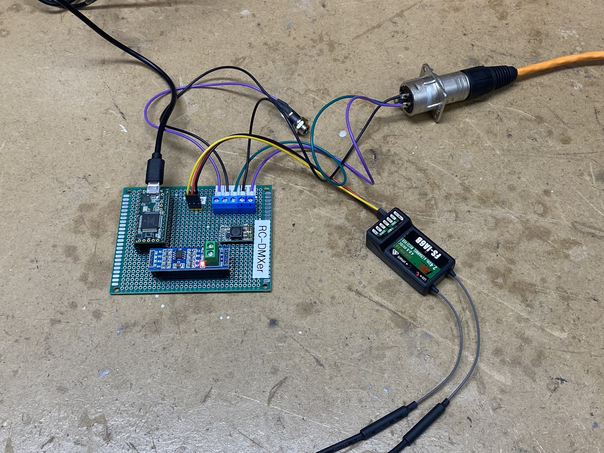
So I putzed around with a few options and came up with RC-DMXer. It takes 8 channels or RC control from the FS-i6 transmitter via a FSiA6 receiver, connected to a Teensy 3.1 (via a single PPM connection) and then spits it out using DMX.
This lets me use the various controls on the RC controller to manually control Eddie. And all I have to do is disconnect the DMX cable from the PC (running VSA) and replace it with the cable from RC-DMXer.
I have to clean up the code and mount it in a box but it works:

The stock FlySky FS-i6 only sends 6 channels but you can easily modify it with 3rd party code to get 10 channels:
This mod also gets rid of the annoying beep if you haven’t moved a control in 60 seconds (changes it to 10 minutes)…
I do have a small issue in that my 6 channel controller actually send out 8 channels via the PPM connection (weird that it isn’t the 6 channels it is meant to do or the 10 channels my transmitter is sending). I’m workgin on getting a 10 channel receiver to test with.
Time to get cracking on the remaining motor controllers…
Nice build and documentation, its looking great!
Not sure if this is useful to you, but there is an Arduino library for connecting to that receiver via ibus and a hardware serial port, it gives you a nice digital link with all the servo positions. Works for 10 channels even on a 6 channel receiver. I’m using it and a teensy on my rc loon.
Thanks… I did look at that I-BUS library and wasn’t sure if it would run on a Teensy… I’m gonna try it out tonight…