You shouldn’t need a hv current probe. It should be sufficient to use a multimeter in series with the LV side of the tube and measure the current. This is how I troubled shoot it last time.
A [Mahoney optical power measurement tool] 1 was really valuable. Science World let us borrow theirs last time and it was extremely useful to ensure we were getting the correct power generated in the UV spectrum.
Do we have (or can we get) a schematic for the laser power supply? I have experience repairing switch mode power supplies and high voltage flyback transformer systems (trained in high voltage procedures). Capacitors, power switching MOSFETs and Schottky diodes can often be replaced same day, with locally available direct replacements or equivalents. Some supplies don’t even need parts, just re-soldering joints that have cracked due to high frequency vibrations. Others just need a good cleaning to remove carbonized dirt that acts as a short circuit to high voltages. Of course, extreme caution needs to be taken when handling high voltage systems, as HV capacitors can store a lethal charge, even when the unit is unplugged.
Given the $$ value of the Laser tube and the years of use already put in on the laser it may be better in the long run to put a new power supply in place.
It’s definitely good to have a back up power supply, but if this one can be repaired, we may be able to be up and running sooner. and least i can dream
Given the $$ value of the Laser tube and the years of use already put in on the laser it may be better in the long run to put a new power supply in place.
Certainly, an understandable position on this situation. Just wanted to offer my help if cost or downtime becomes a major issue. Also note that, though new is often better, it isn’t always so. Some new equipment is made with mediocre parts, and actually works better when name brand, or more robust parts get put in. Seen this many times with low ESR caps.
We don’t have a schematic. We did open it and inspect it, tested fuses and the power transistors. We found no obvious issue, but our troubleshooting was far from exhaustive.
Well, that’s bad timing. How dare that machine break now? Why couldn’t it have waited until after my mom’s visit? I wanted to show her how it worked by making something cool for her! (grumble, grumble)
Thanks for the update, LCC. And thanks for your hard work on the laser cutter.
Hi guys, thank you so much for taking care, ordering the parts, investing your time, etc. Feel free to count on me if you need any help. I will be more than glad to offer my time as well. Have a great evening.
I wasn’t able to find a schematic for the power supply while searching online, but I’m still willing to attempt a fix. Am at VHS right now (Wed Mar 1 8:15pm ), so if I get permission from a Laser committee member within an hour or two, I will take a look.
Thanks, will peek around, but won’t actually attempt repairs today. Just a scouting mission for what parts are being used and how, so I can look up some datasheets. If I find anything unusual, I’ll let you all know. BTW, do you know if VHS has a resistor dummy load to take place of the laser tube while testing power supply?
Yes, I have seen a few large wattage resistors and an adjustable 10ohm 50watt potentiometer as well. If you can’t find them pm me and I can meet you at the space.
Also, it’s worth pointing out that the laser’s power supply died a few months ago and it was replaced. I believe the old power supply is in a box labelled power supplies under (or near) the microscope bench. That means you would have two power supplies to play with.
I have some 40KV wire if you need some for testing as well.
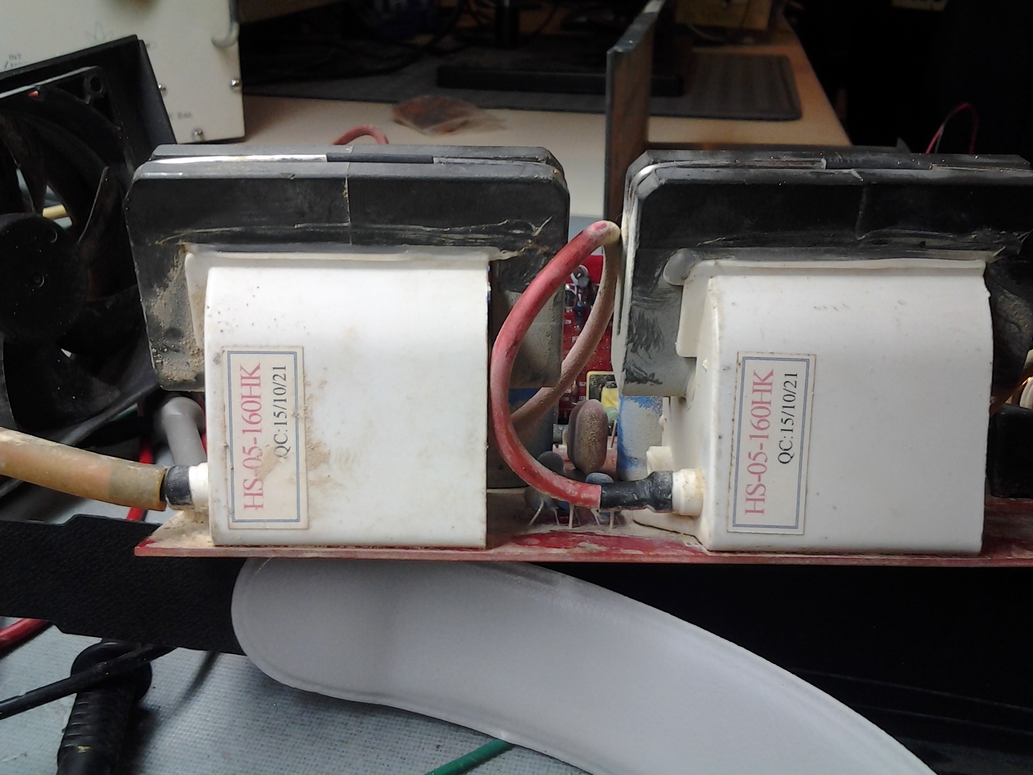
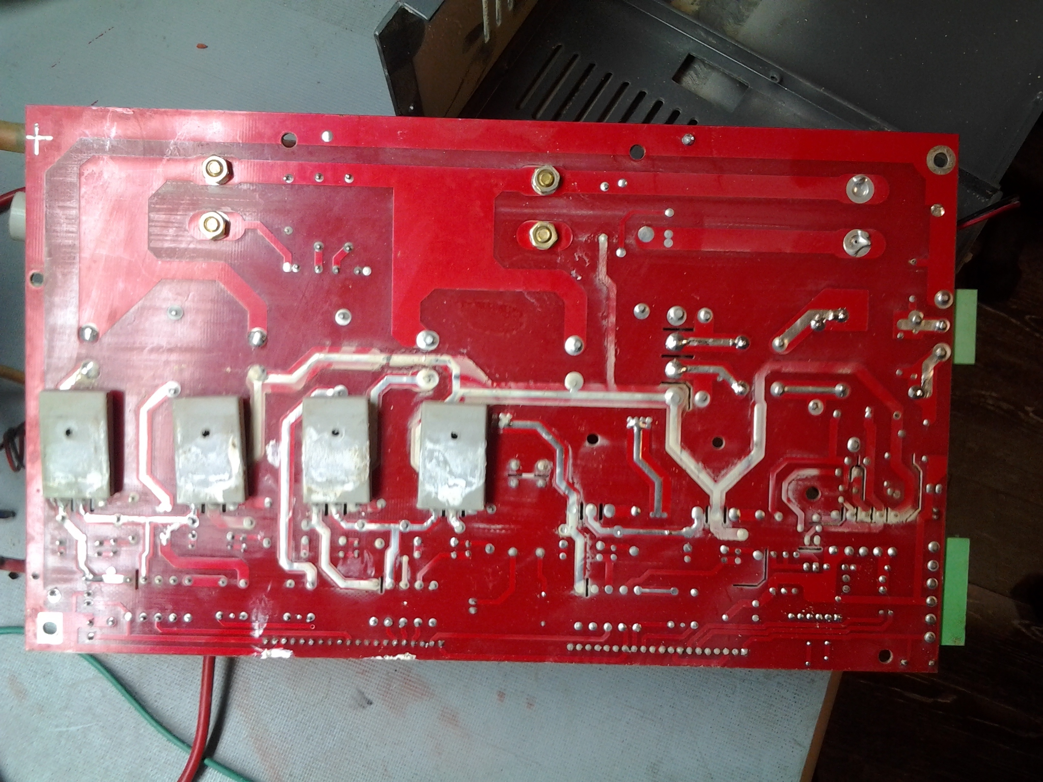
Below, bottom of power supply board showing 4 main switching MOSFETS that drive the flybacks. The white residue is normal. It’s thermal compound that helps transfer heat to the outer case :
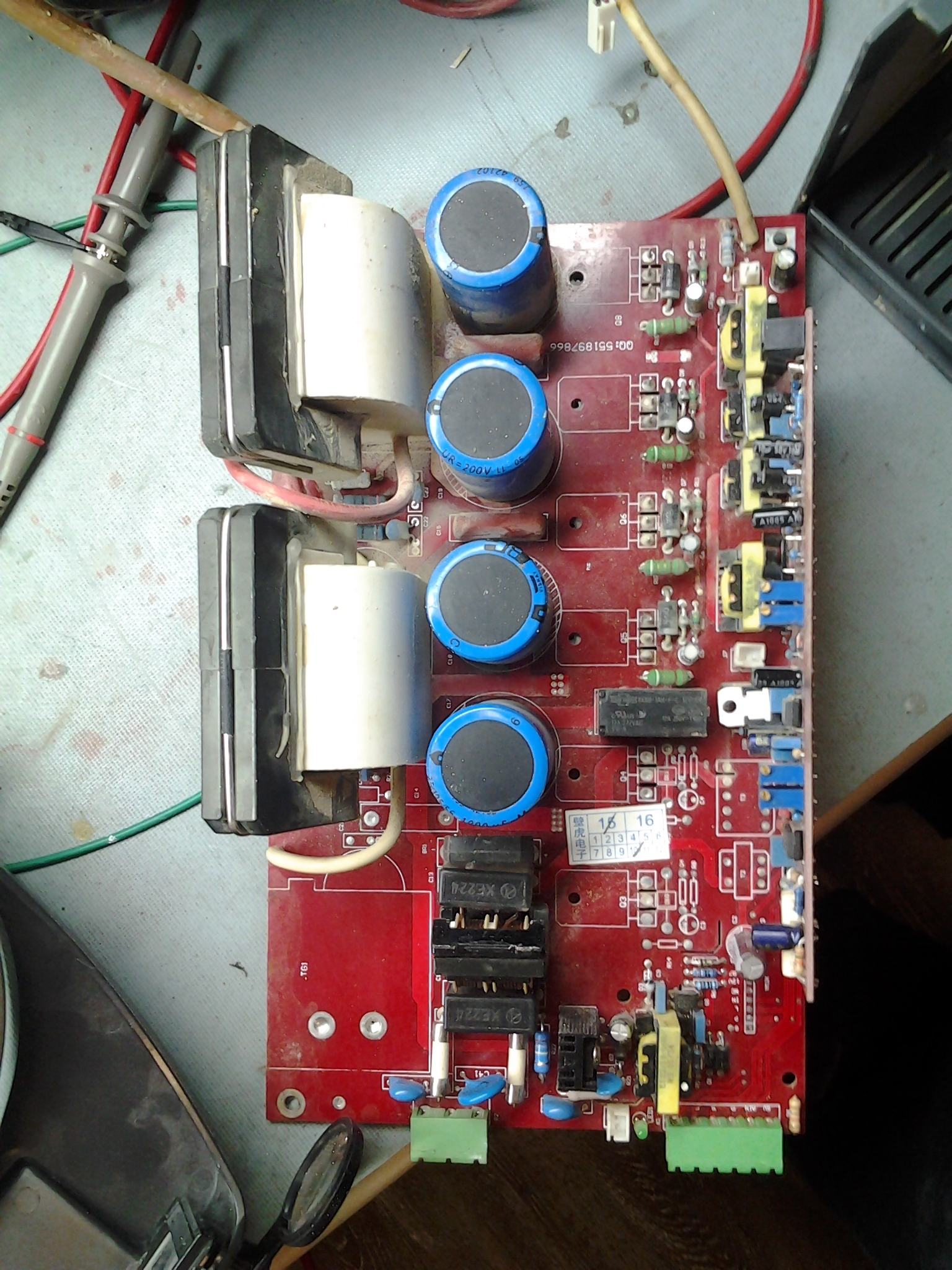
Below, Top down view of main PS board showing flybacks on the left and the big blue filter capacitors that feed them with DC (rectified) mains power The four black lumps below them are the main bridge rectifier and the LC line filter capacitors and inductor. Below them are two ceramic power fuses (white) and the RF suppression caps (small blue) and control logic wiring connectors (green).
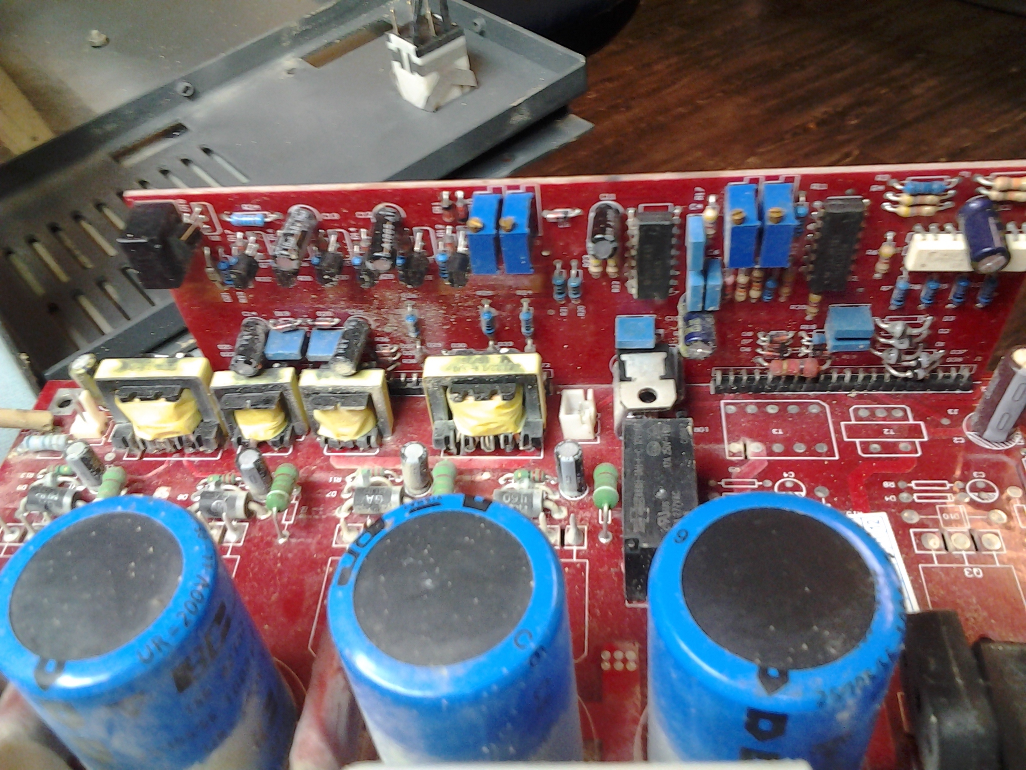
So far, no obvious visual signs of physical damage such as burning, arcing, blown caps or cracked solder joints. Will do more in depth testing at next opportunity. Will any key holders be at VHS tonight? I don’t see any calendar entries for this evening.
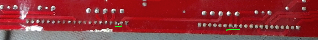
I’m an electronics n00b, but A couple of pins (in the daughterboard connectors?) look like they might be bridged (green underlines in image), plus the general dirtiness might be hiding problems.
Presumably very little of the dust will contain conductive materials, but you never know, you know?