Charlie: The talking, seeing, balancing robot

A brief description of the goals of the project are to create a robot that is able to interact with the world in a semi-natural way.
I have been reading a lot about openCV facial recognition, and also the amazon alexa or google home type speech and talking interactions and realized that it would be awesome to have a robot that could a) recognize people (distinguish different people, and identify a person that it did not know), and then interact with the person using STT (Speech to Text) and TTS (Text To Speech) algorithms. A simple example would be to say “what is your name?” if it did not recognize you, and then possibly store a number of facial images from you that would allow it to later say “hello, Roland” for example.

How could this be done?

Well, here are my first thoughts on the subject. Following posts will be describing the progress that I have made so far.

  1. TTS and SST: there are several dedicated *nix SBC (Single Board Computers) that have been built for hobbyist to accomplish this goal fairly easily. I have narrowed it down to a really good candidate - The Core 2 Respeaker board from seedstudio. (ReSpeaker Core v2.0 | Seeed Studio Wiki)
    They have lots of tutorials and examples to play with that allow you to run a version of amazon alexa out of the box. It has plenty of processing power and also an on board DSP chip with 8 microphones that can do beam finding and other cool stuff to allow the little guy to hear you properly.

  2. openCV visual object recognition: Decided that a dedicated SBC was also the way to go here, and narrowed it down to the http://wiki.friendlyarm.com/wiki/index.php/NanoPC-T4
    It has tons of processing power for an SBC and also 2 CSI camera ports to allow stereo vision capabilities (distance detection), and could easily run openCV and be able to recognize faces or other complex objects in real time. Have not have too much chance to play with this guy, but I bought it have started building it into the robot head design.

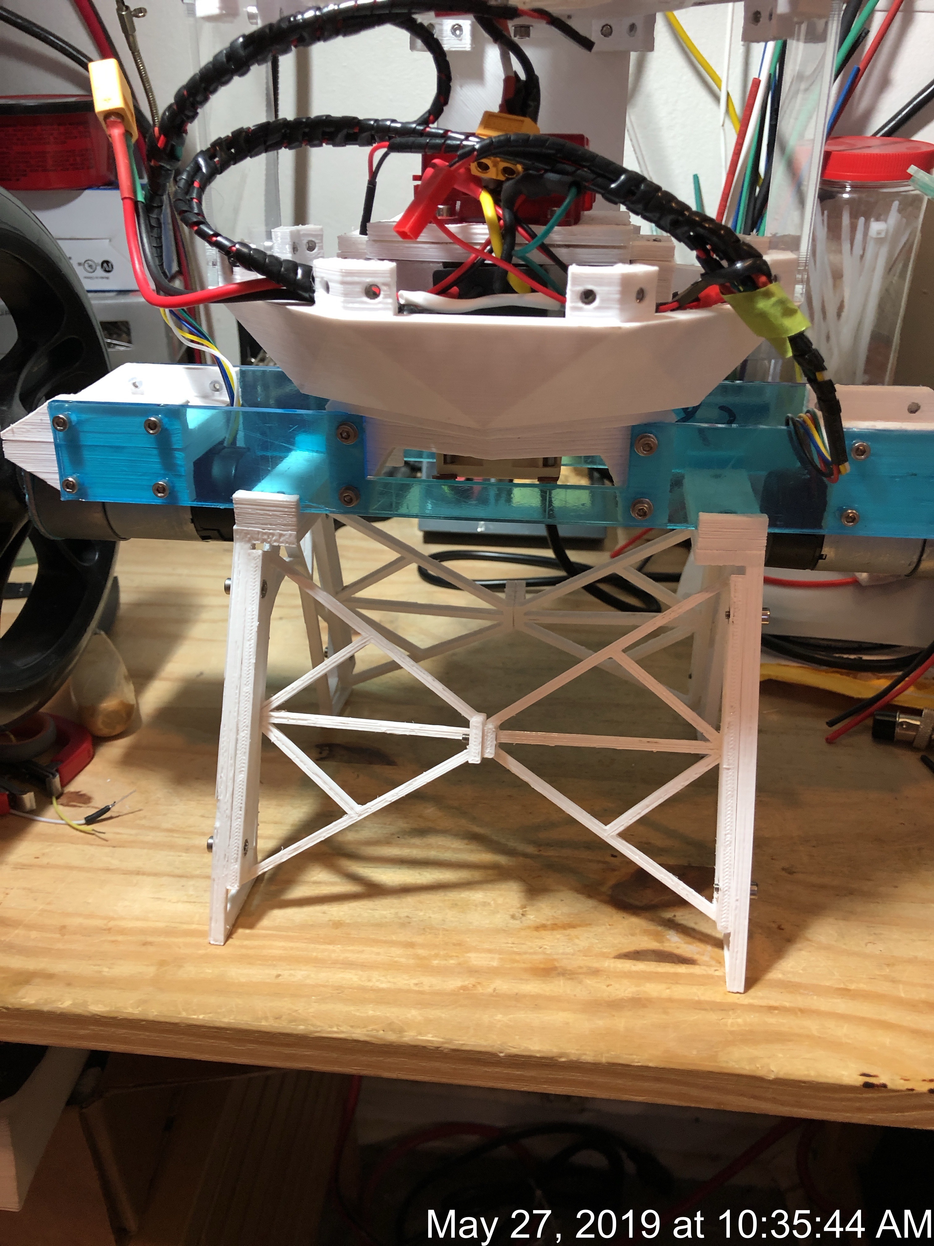
  3. Balance Bot: because why not. A robot that can not demonstrate dynamic balancing will definitely not appear intelligent enough for the project. What way to scream “I understand my environment” like a balance bot. I was planning on building a big version of the balance bot on the ardurover page in order to save time and then think about how the speech and vision brains will talk to the wheels and direct motion.
    Finally, there should also be a “rest” mode, so I designed the balance bot with a retractable “foot” that can be extended when batteries are low, or the robot wants a break.

Put it all together, these are the essential elements of the project. A balance bot, that will have a sensor head incorporating two dedicated SBC computers that talk to the body and allow it to see people, roll up to them, ask them their name, etc…

What I have acquired so far:

  • The core 2 respeaker

  • The NanoPC-T4

  • Two CSI camera modules for the NanoPC-T4

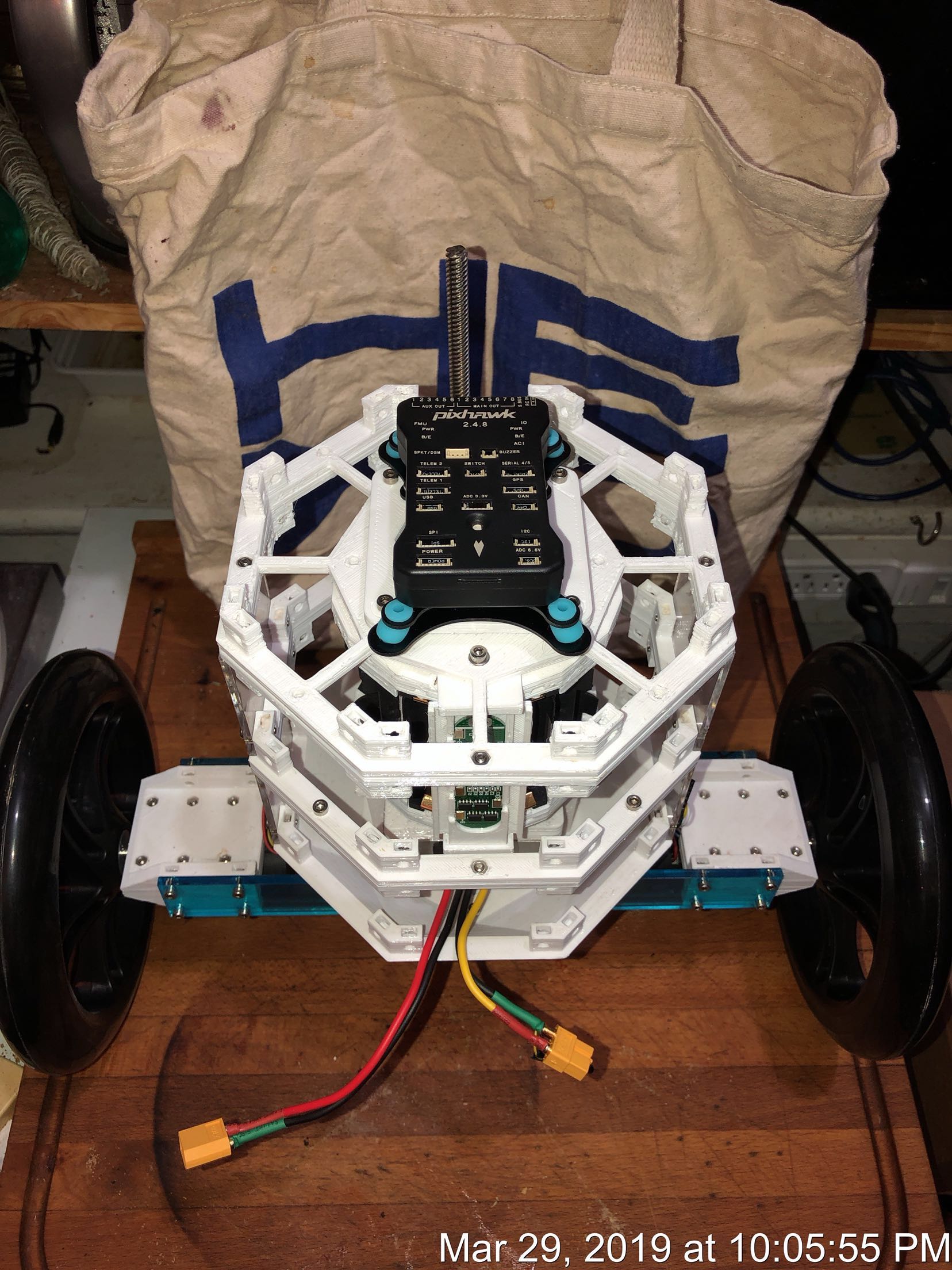
  • A pixhawk flight controller for the balancing

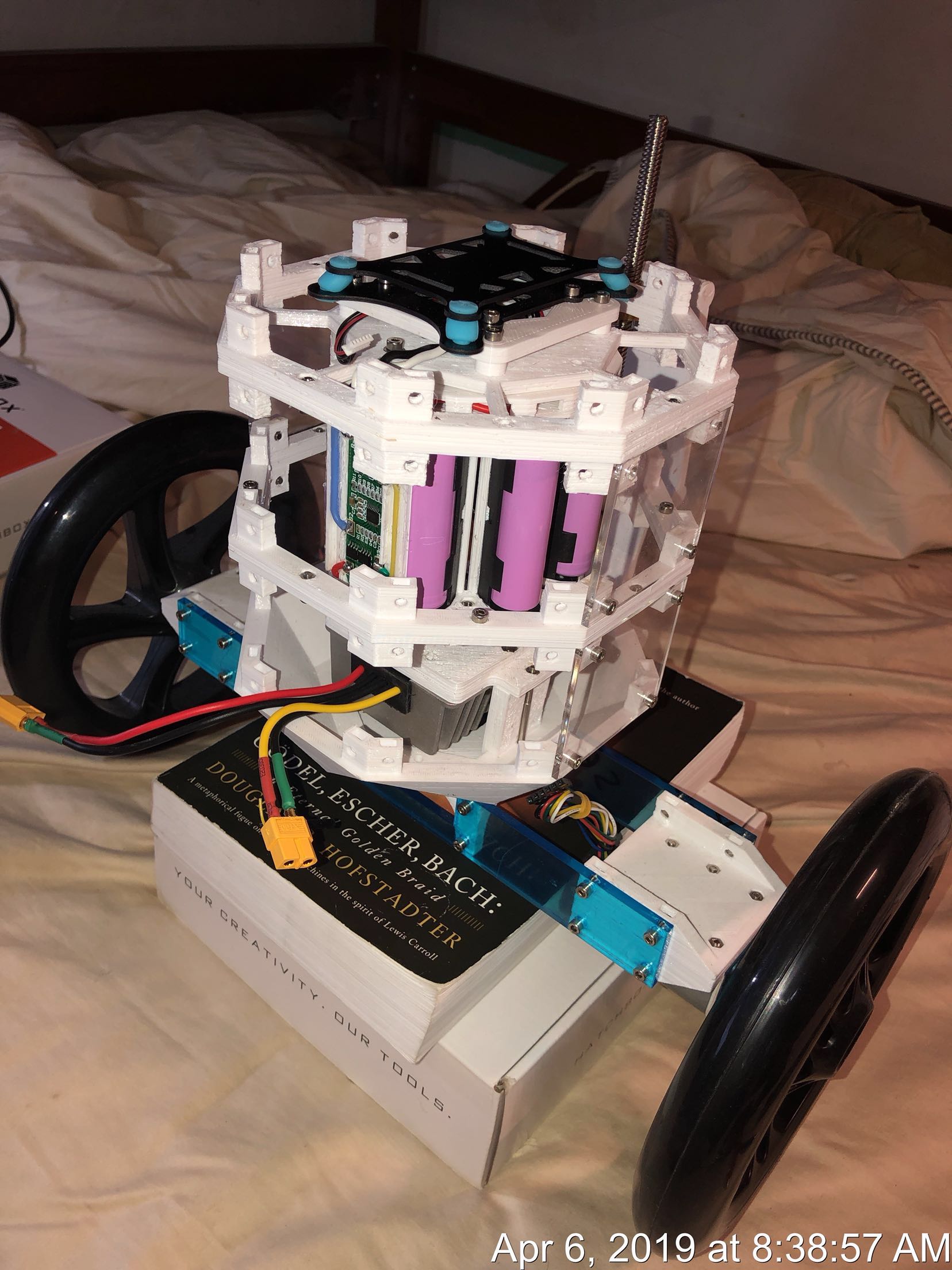
  • A motor controller, and two pololu geared motors, with nice giant wheels

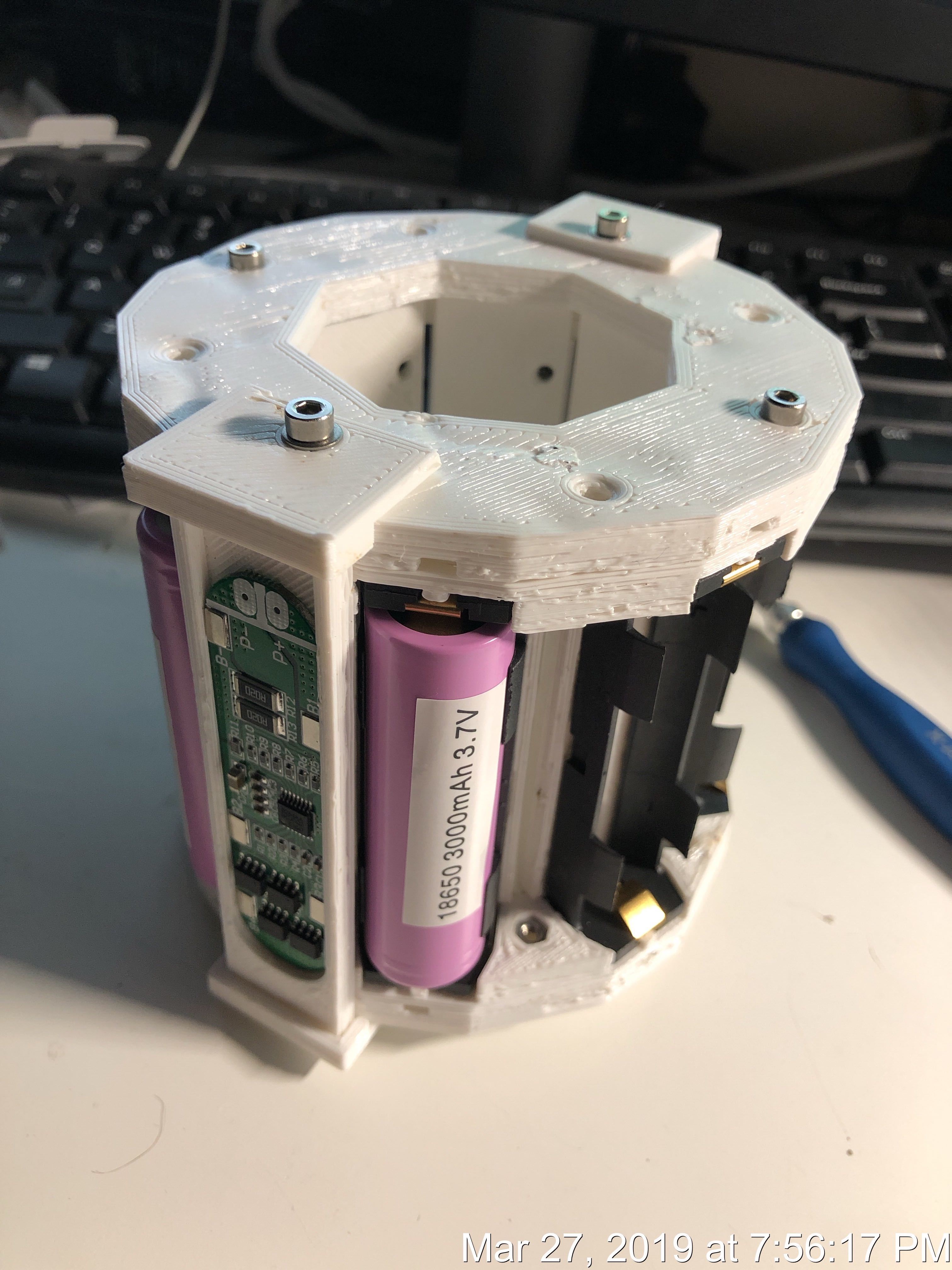
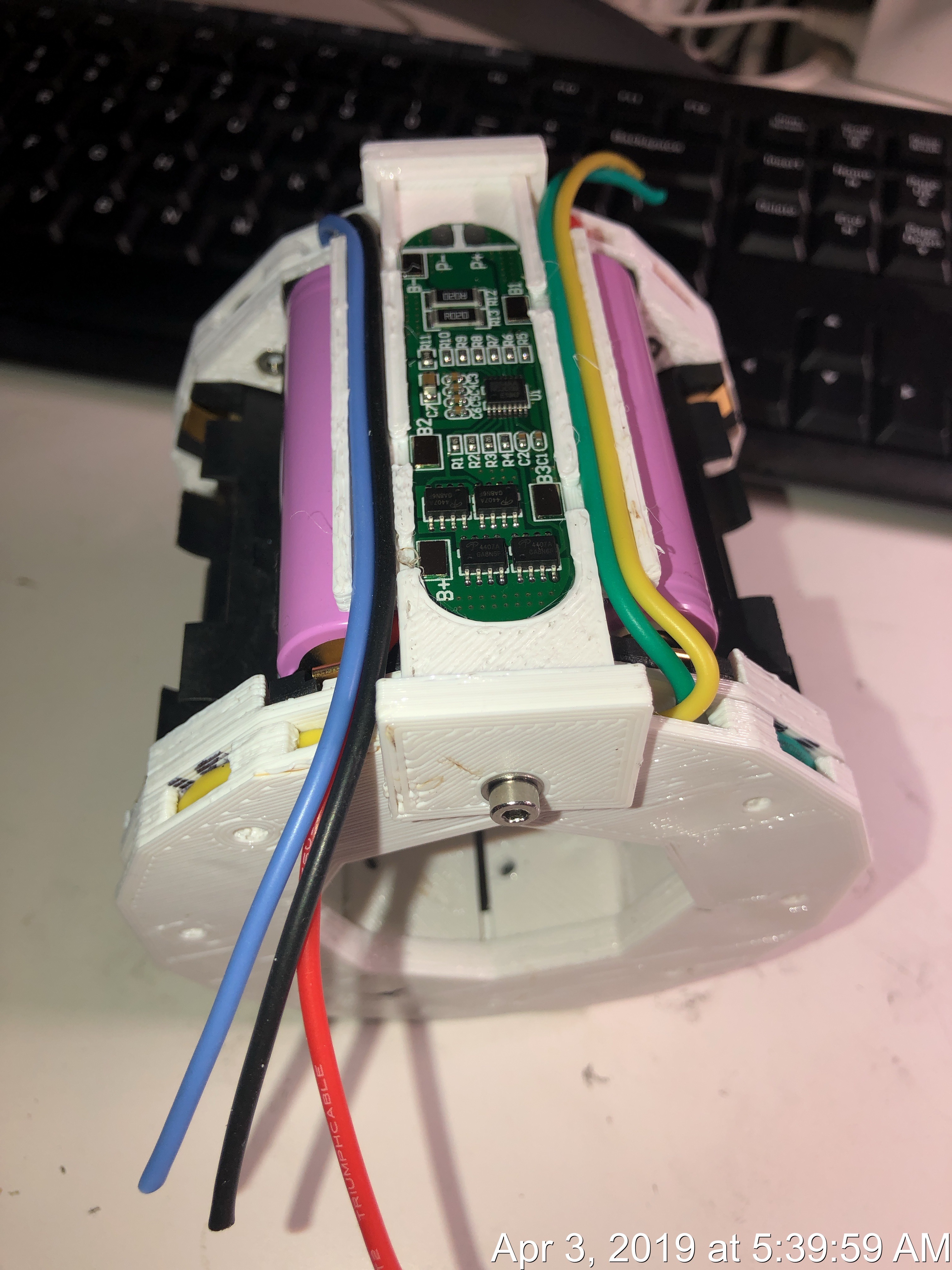
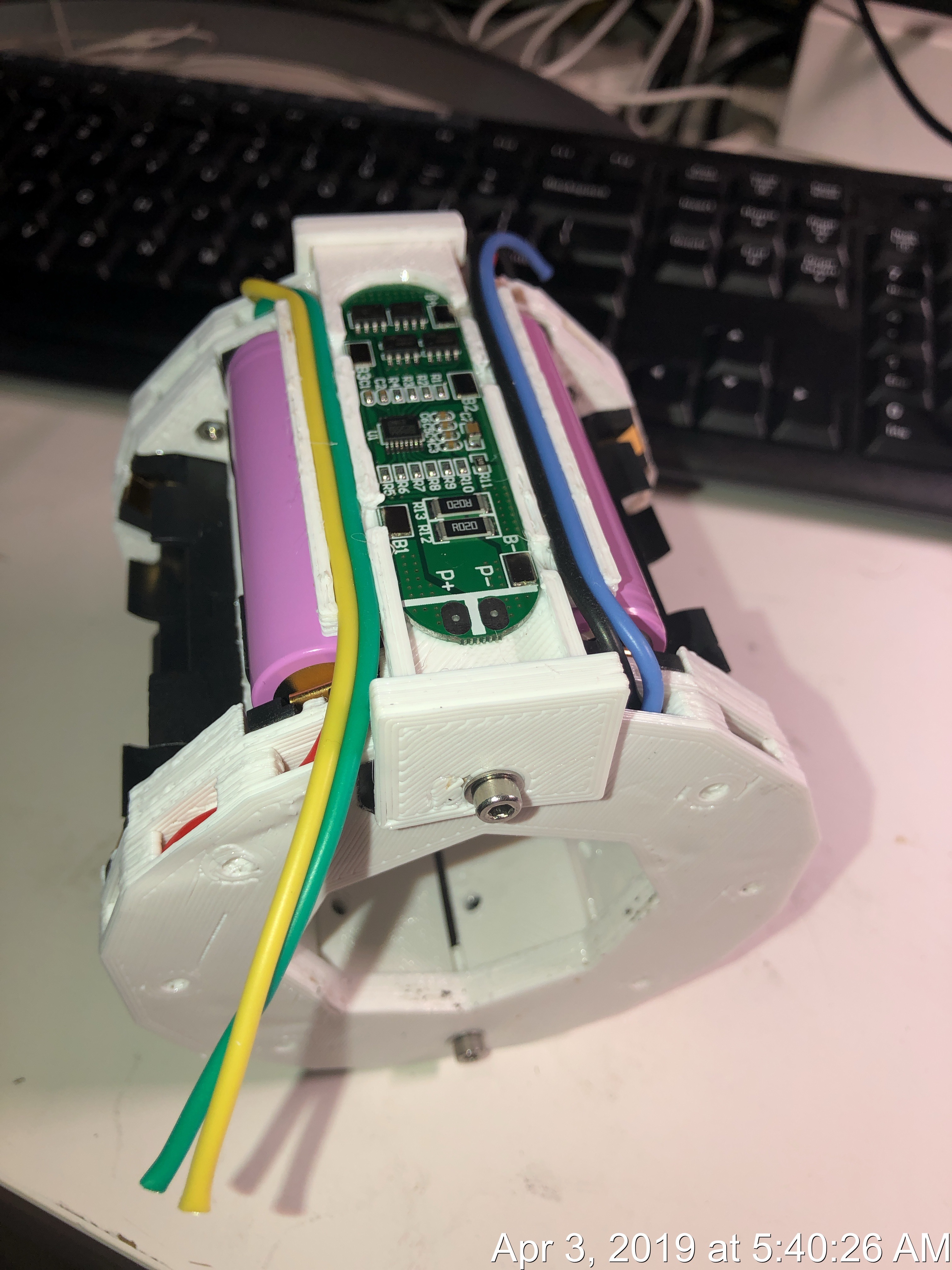
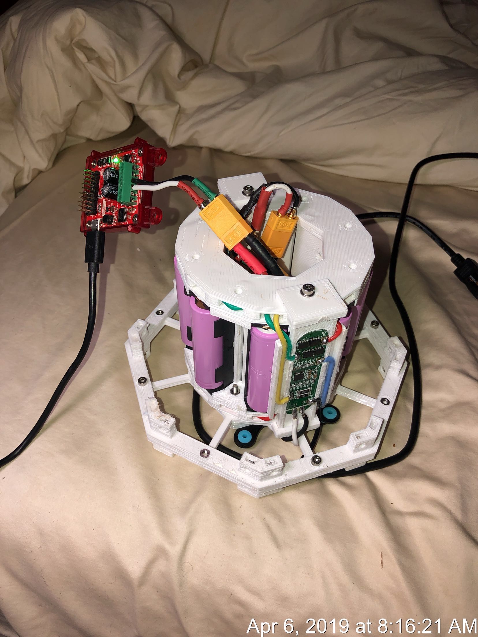
  • lots of 18650 Li-ion batteries for hours of robot fun (also battery holders and BMS boards for the custom power system

  • a high power 12V regulator to run the wheel motors

  • a small lazy suzy platform so the head can swivel

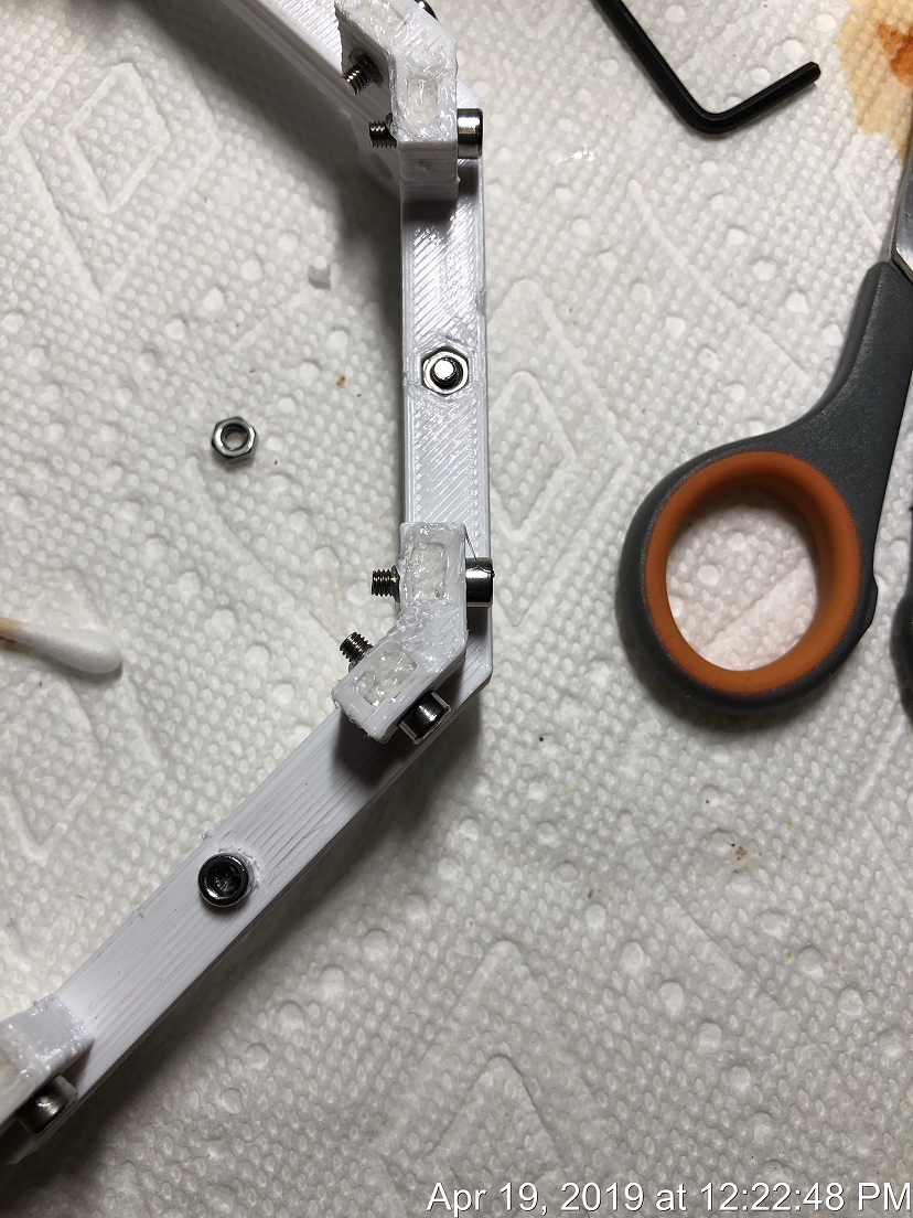
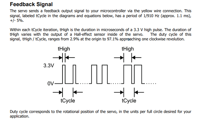
  • two continuous rotation servos that will move the head around

  • lots and lots of 3D printing to put all the pieces together.

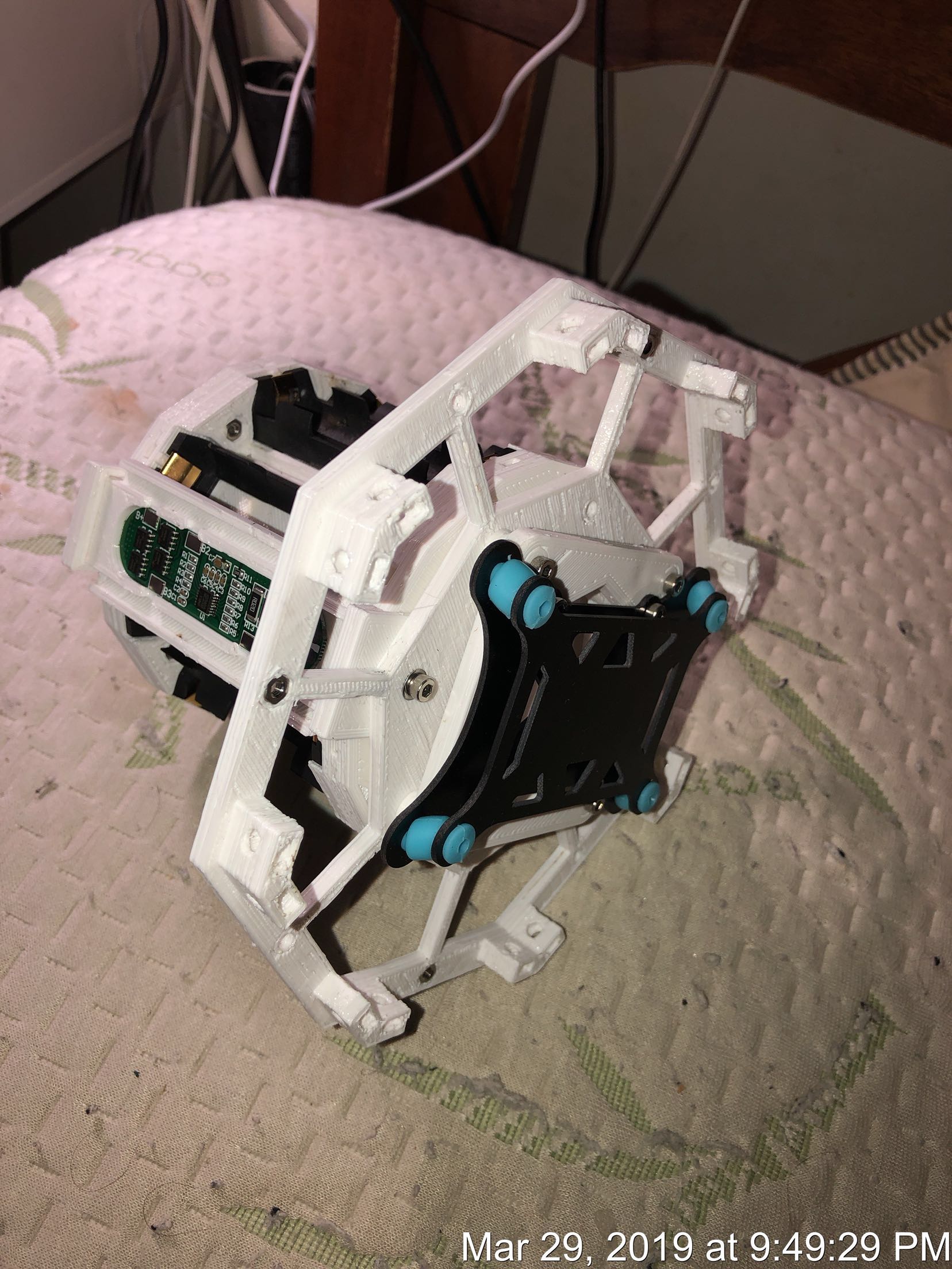
This is what the body looks like now…

This is what the head looks like now, I am testing the servos that will move the head around and up and down

This is the head with the SBCs fully mounted to give you a better look at it all together

Stuff left to do (So much!, but lots of fun)

  1. Finish the head movement mechanism
    Servos are basically mounted but need to be connected to the SBC with some simple test scripts.
    Also want to install some optical stops so the head can not break itself by rotating too far.

  2. Finish the power system - this is fairly close. I have the right wire on the way, and have regulators for 12v and 5V up the wazoo to power the wheels and the SBCs all at the same time. Also have mostly figured out how the wiring will be routed.

  3. Start programming the vision SBC and speech SBC to talk to each other and also talk to the pixhawk. This will be the biggest challenge once the physical beast is put together, making it move around and perform simple checks and tasks. Super simple tasks like recognizing objects like pencils and coffee cups, and then saying “pencil” and “coffee cup” will definitely be one of the first cool applications. Object following with the head will also be very cool at first.

Here is a link to some extra documentation on google I have been making along the way, with some parts that I purchased.

Finally, why is it called Charlie? Well, no good reason. I played around with a lot of acronyms that spelled “ISAAC” (Interactive Speech yada yada) but they all sounded very boring and laboratory. I wanted this robot to interact with people, so I wanted it to have a friendly name. My girlfriend chose Charlie.

What do you think?

6 Likes

New images of the Li-Ion power system. This will be 2P 4S 18650 Samsungs (4 in series then two of these in parallel). Should be a total of 3Ah X 3.7V X 8 = 89 Watt-hours of power!

Note the vertically mounted BMS boards from Aliexpress. Each board will run one 4S pack at 10 amps, so the parallel combination should be able to supply 20A. This should be more than enough considering that the stall amperage of the wheel motors are 5A each and should not draw more than 1 amp during normal movement. The SBCs should only add another amp or two to the total power draw (need to measure this at some point)

4 Likes

Early testing of the speech brain part of Charlie. The respeaker board comes with some easy demos that allow you to test all the STT and TTS parts with reprogramming in python script. I adapted an amazon demo to have it recognize its own name.
Wooohooo!!

2 Likes

That’s cool. What does programming it look like? Is there some sort of on-board wifi so you can SSH in and write Python on the board?

1 Like

Both the respeaker and the NanoPC have physical ethernet and WiFi options. They are both fully functional linux machines, so sky is the limit!

3 Likes

NanoPC has lots of GPIO pins, so maybe that is the best choice for how to interface with the pixhawk for motion control, and also to control the servos for the head (these are minor details I have not fully worked out).

2 Likes

Uploaded all the STL files. Lots of them are not current versions. Need to take some time to trim the files and only include latest parts.

3 Likes

Wiring has begun on the battery pack. Soon I will begin testing capacity etc.
I am happy with the way the layout is working so far. Also I am following the most common wiring convention for 4s: black, yellow, blue, green, red
This will hopefully help when I need to diagnose problems.

3 Likes

Both sides of the battery pack now fully assembled. BMS units on both sides seem to work like a charm. Tried charging each side until a common voltage of 15.4V was achieved, then connected the two sides to complete the 2P configuration. Also tried a test assembly to see how much room I left for the motor controller on the bottom. Does not look good. Probably need to increase the size of the acrylic side panels a bit in order to give more room for the base motor controller and power supply for the legs.

1 Like

IT LIVES!!
But yet is not quite alive.
First motor tests using the new battery pack and the Roboclaw 2x7a motor controller. Motors respond well. No sign of anything overheating. Next steps I want to check the power draw.

2 Likes

Today, I have the day off, so I am going to do a few hours of the tedious not so exciting work to put the rest of Charlie’s exoskeleton together.
Many moons ago (probabaly about a year ago), right after getting my 3D printer, I discovered the wonders of nut capture technology.
This post is intended to share a bit of that magic, and maybe spur a discussion into what other solutions or similar solutions people might have found.

OK, Nut Capture Technology: the ability to grab an M3 nut and then allow your 3D printed designs to be bolted together in a modular fashion.

  1. Design little channels that are the right width for the thin width of the nut but will not fit the long width of the hexagon. I also made the bottom of the channel have a divot that will exactly fit the pointy bit of the hexagon and allow the nut to nussle itself in there until it is fixed by some silicone and paper towel.

Note that I used the M3 screws to hold the nut in place as I glue them in. This I had to learn by trial and error. If you just trust that the nut will sit in the right place, you will be super disappointed when it moves around, rejects your screw after glueing, and then you need to bust your piece to get the nuts out.

Step two: add a little bit of silicone sealant

Don’t add too much. You want just enough to fix the bolt in place but not too much that the goop will start oozing out everywhere when you jam in the paper towel.

Step 3: Jam in some paper towel (1cm X 1.5cm approx.)

The paper towel acts like the wadding in an old cannon. Just stuff it in there and it makes sure that the silicone gets in all the cracks and the nut will be securely fixed in its little hole. Don’t want that nut moving around after the silicone dries!

Step 4: Seal in the Paper Towel Wadding

I always add a little silicone on the top of the wadding for good measure. This ensures that the paper towel does not start pealing out at some later date and compromise the whole piece. It is probably mostly aesthetic, but I stick by it because nut capture holes done in this way have never failed me.

3 Likes

Oh, by the way, solved the wiring problems I had at the April 9th open house. I believe that it will balance now, but need to assemble everything again for testing!

2 Likes

The silicone / paper towel wadding is an interesting approach. Does the paper towel make a difference? Could you get away with hot glue instead of silicone?

I’ve also done this style of but insert with a 3d printed indent to keep the nut from moving.

If you have never tried them before, you may want to look at brass heat-set inserts.
A good guide is here: Threading 3D Printed Parts: How To Use Heat-Set Inserts | Hackaday

They look pretty when done well. Also apparently stronger than tapped or printed threads according to one informal study I saw. (Which unfortunately did not compare slotted nuts).

I’ve found them especially helpful when space is tight, or the print orientation would require some awkward support material. Though I’m typically using larger fasteners so the size of the but is on the edge of what you can bridge reliably.

1 Like

Thanks @JDMc !
The heat set inserts do look a little more cool.
This method I basically developed on my own. I don’t have a lot of experience with glue guns but I see no reason why it could not be used.
The main thing for me was to hold the nut in place solidly enough without too much expectations on the tolerance of the printer. My printer tends to go wonky fairly often, and I needed a way to fix them in place easily.
The paper towel I found through trial and error.
First, I just wadded in the paper towel because I did not want the silicone leaking out of the bolt holes. This was not sufficient for holding the nut, however, and several of them started to move around and create really frustrating assembly issues.
This is why I went to the silicone/wadding/silicone technique.
Its been failsafe since then.

OK, my next frontier is…

In order to control the head movement, I need to run two servos off of the GPIO in the NanoPC-T4. Luckily, the control is basically a clone of the Raspberry Pi and they even support the RPi.GPIO python library. This is cool. Now, the servos that I am using are the Parallax Feedback 360 high speed servos and they are equiped with awesome feedback sensors that can measure the rotation of the servo.

Ideally, this can be used to measure the angle of the head and prevent Charlie from hurting his neck if he forgets where his head is.
Unfortunately, the feed back is based on the pulse width of a 910Hz signal. This means that I can either measure the width of the pulse with the NanoPC-T4 (which might be a pain), or use a dedicated arduino for pulse width measurement and then feed this data back to the NanoPC-T4.

I’ve seen implementations of this kind of solution (arduino → flight controller) used for RC measuring, so in theory it should work.

Anyone care to comment?

My first thought of a “clever” way to do that would be to abuse the board’s UART capabilities. Just set up the serial baud rate and encoding such that a 0-ish is the readback 0-value, and so on.

Here’s the page from that servo’s datasheet:

Quickly looked into how to do that, and I think pigpio will do that on a Raspberry Pi at least, without even anything being abused. It seems to have hardware timers built in. Does it work on your board?

Also throwing another vote onto the “heat-set inserts are amazing” pile :slight_smile:
You should pick some up with your next AliExpress order, although your captive nut method looks like it works out well for you, too. Having both techniques in your toolbox is great!

This may work. I know that they support the RPi.GPIO library on the NanoPC series. Maybe someone ported the library to NanoPC, or it may just work. My feeling is that the NanoPC GPIO section is just a copy of the Raspberry Pi and may use the same chip even. Don’t quite know enough at this point.
Thanks!!

Sorry… maybe someone ported the pigpio library. need to do more research.

On the previous thread, I’ve decided to get design a STM32 based solution for the control signals. I need some intelligent control since the servos will rotate an indeterminant angle to move the head a certain angle (need to measure this). The STM32 can then also handle the rotation angle measurement and calibrate everything so that the seeing brain can more simply point and shoot. Some testing has begun, but slow going due to free time issues.

Upgraded Charlie’s “test stand”. Got tired of balancing him on a bunch of books during testing. Now inspired to build a set of “training wheels” so he can move around without braining himself.

5 Likes