I’m starting to get my 3d models into the design; these will be used in both enclosure generation as well as documentation images.
Here’s an early rendering.
Adding a GL orthographic render, I think I like this more:
I’m starting to get my 3d models into the design; these will be used in both enclosure generation as well as documentation images.
Here’s an early rendering.
Adding a GL orthographic render, I think I like this more:
This looks really professional!
I don’t claim to understand the use-case, but there something that came to my mind while admiring the rendering…
Those potentiometers or rotary encoders at the top are quite close together. If you haven’t already, I suggest checking that there is enough spacing for the knobs that go on to the shafts. I had to redo a front panel because of this once…
There is also a usability aspect of having knobs very close. In my last project, I glued all the knobs and buttons and stuff on a printout of the circuit board and played around with them to see how it will feel. I ended up spacing the rotating knobs further apart so that my fingers have space to go between. Really depends on how you plan to use it.
(If you haven’t gotten the knobs yet, 3D printing a rough approximation of their shape of them worked well for this purpose)
Thanks!
I’ll likely be turning my own knobs, but yes, they are tight but I’ve ensured clearance between each knob.
In reality, if I were making the above layout, I’d probably just omit the knobs above the buttons to give more room in-between the channel faders. They are potentiometers rather than encoders. I have ordered both center-detent and non-detent ones depending on how the user wants it.
The primary use is to use it as an input device for either DJing or mixing, but the flexibility of it is intended to support lots of layouts. For instance, if you just wanted a 16 button hotkey keyboard, this can function as that.
It is a small board for a couple reasons. Primarily, due to price. Once you go over 100mm x 100mm, the price goes up fast. The second reason is I want these to be very portable. If someone needs more buttons/sliders, there’s nothing saying they can’t run 2 of them (they could even put 2 in the same case).
You are right though, it can be cramped when you populate every piece in there.
It has been a long time since I posted…
I ended up sending the board off and ordered all the components. Once I got them all and the board, I looked it and basically shat myself with how much work it would be to assemble the board. Certainly not appropriate for my first surface mount project. I lost momentum a bit. Here’s what a partially populated board looks like to get an idea of look and feel.
But the reality is; I’m just not excited about what it came out as. But this isn’t over!
Instead, I’m using it as a reason to change this into something a bit easier to manufacture.
I’ve changed out my software stack a little bit. In the year since I started this project, there’s been some maturity in libraries, and I’m currently on the phase of checking out hardware.
Another thing I didn’t expect is that the slide potentiometers I planned for aren’t in abundance at the space (don’t get me wrong, lots of slide pots at the space, in fact, too many, go use some, but many of them are audio-taper, and almost none of them are 10kohm. I can use different values, but it effectively became a mess). They are also a bit more difficult to get than I anticipated.
So Instead, I’m going to be trying something a bit different. I want to attempt to design something I can get manufactured where most of the components (pretty much all the surface mount at minimum) are assembled. Right now seeed has PCBA, so I’m going to try that out. I’m trying to use parts from the open parts list as much as I can to make manufacturing easier, and where I can’t I’m trying to find parts that are easy to source.
On the software side, @lukecyca’s/craft metrics ESP32 libraries have been awesome. In the past I’ve used his debouncer, and now I’m considering using his ADC library (GitHub - craftmetrics/esp32-mcp342x: ESP32 compatible library to interface with the MCP342x class of Analog-to-Digital converters). I’ve now gone through 3 ADCs in search of the right one for this project.
I have some hacked together code so far. It works but isn’t elegant. It does the following:
I’ve hooked it up to Traktor (in demo mode) to validate the end-to-end. While my sample rate isn’t great (just need to write that loop, lots of of extra delays in it right now) this is what it looks like as I control it.

I need to break a couple things down in hardware and software, and some need to happen before others.
For instance, one of the paramount concerns I have is latency. Luckily I’ve already got both input and output midi services implemented, which will let me test latency. There are lots of bits with latency I can’t change. For instance, I can’t change the computer BLE software/driver stack latency. From my reading, I know that some BLE stacks are slower than others. I also can’t change the hardware/protocol communication latency. These are all sources of latency I have to live with, but my research suggests they are, at best case, well under normal perception.
Where I can affect latency, so far, is:
Back to measuring, if I can get my button hardware and code roughed out, then I can hook up the logic analyzer, set Traktor to feed back my input to an LED on the controller, and basically measure the delta between the initial state change and when the LED lights up. This will let me determine what the best route is, or at least if a route is acceptable.
More to come soon…
I’ve been refining the code quite a bit, cleaning up rough edges and one crash I had.
I’ve got one button implemented (again, thanks to Luke’s esp32-button library), and since I have different sampling tasks, I now have a ring buffer that can accept commands and orders them into bluetooth commands. Theoretically it supports joining multiple commands into a single command if there is more than one in the buffer, but I haven’t gotten into the case where my sampling is faster than my bluetooth transmission time. If this case were to happen, it can omit one duplicated timestamp and join multiple commands into a single packet.
I’ve also implemented a hysteresis/filter for my analog inputs. This makes it so I don’t duplicate the same value, and I get a micro latch when changing directions to prevent any unintentional bounce back when you let go of or stop an analog control (such as a slider). The latch is on the level of a single value, but it just reduces the extra noisy signal you might get and retains the user intent a bit better.
On the software side, this weekend I was working on providing saved settings for what each button/analog input maps to using non-volaitile storage. I understand that most DJ controllers will allow you to remap buttons, but I figured I should, at least internally, have the ability to do custom mapping on the controller side too.
On the hardware side, I’m looking into power path and charging. I’m seeing that getting a proper charging circuit might be pretty difficult, but at least there are good reference designs. Given that this portion of the circuit would be super useful in a lot of other projects, I’m considering building this part of the circuit first, getting it made to validate it independently, and if I get a good circuit working, then I can use the prototypes as power supplies for other future projects.
Many of you have seen me quite active on the circuitry front. Some of that was to help validate portions of this project, and some of it was to improve my circuit designing skills.
What I’ve ended up with are several boards in the mail, lots of parts waiting for boards, a bunch of great knowledge (special thanks to @lukecyca who keeps furnishing me with amazing insights).
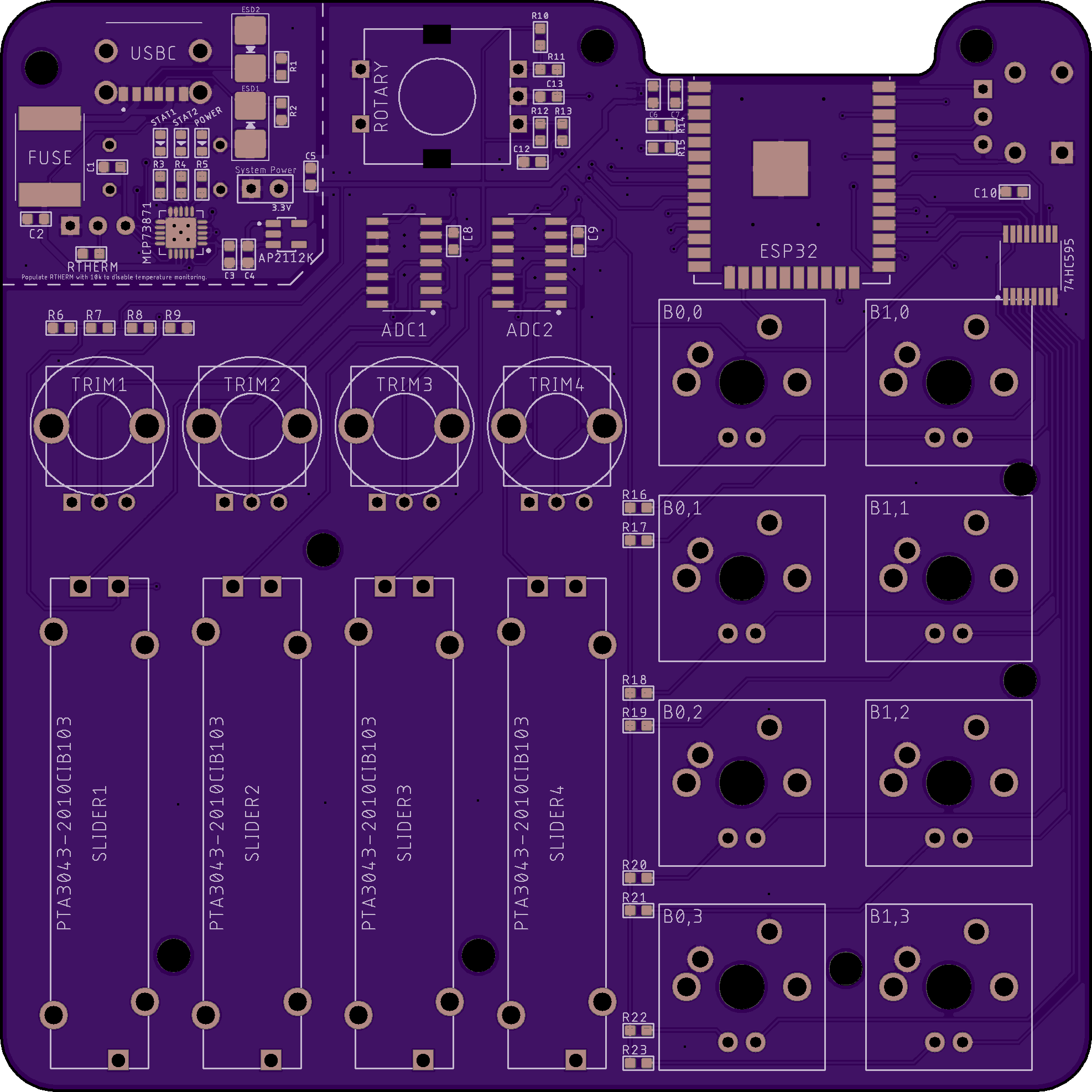
I’ve taken the in-progress version of the Bikeshed board and mapped it to a new version of this project (but not bike-shaped, and only one USB connector ![]() ). I standardized on 0603 or larger, so all the little flea-sized 0402 I’ve scaled up.
). I standardized on 0603 or larger, so all the little flea-sized 0402 I’ve scaled up.
I implemented (thanks to Luke’s links) local grounds for my high frequency devices (ESP32 and ADC) and also limited my power supply to a localized path with holdouts and my final filtering capactor for my supply output is nearby (essentially local-grounding the supply as well). This as I’m reading, effectively reduces the effect of the whole ground plane forming as an antenna (both input and output).
I’ve also taken a new approach to how I assign components. There’s probably a more automated way of doing this, but effectively anything that can be remapped in software, I defer the pin assignments, and only make the pin assignments as I lay traces. This allows me to jump less. It’ll be one more level of abstraction in the code, but that’s what code is meant for.
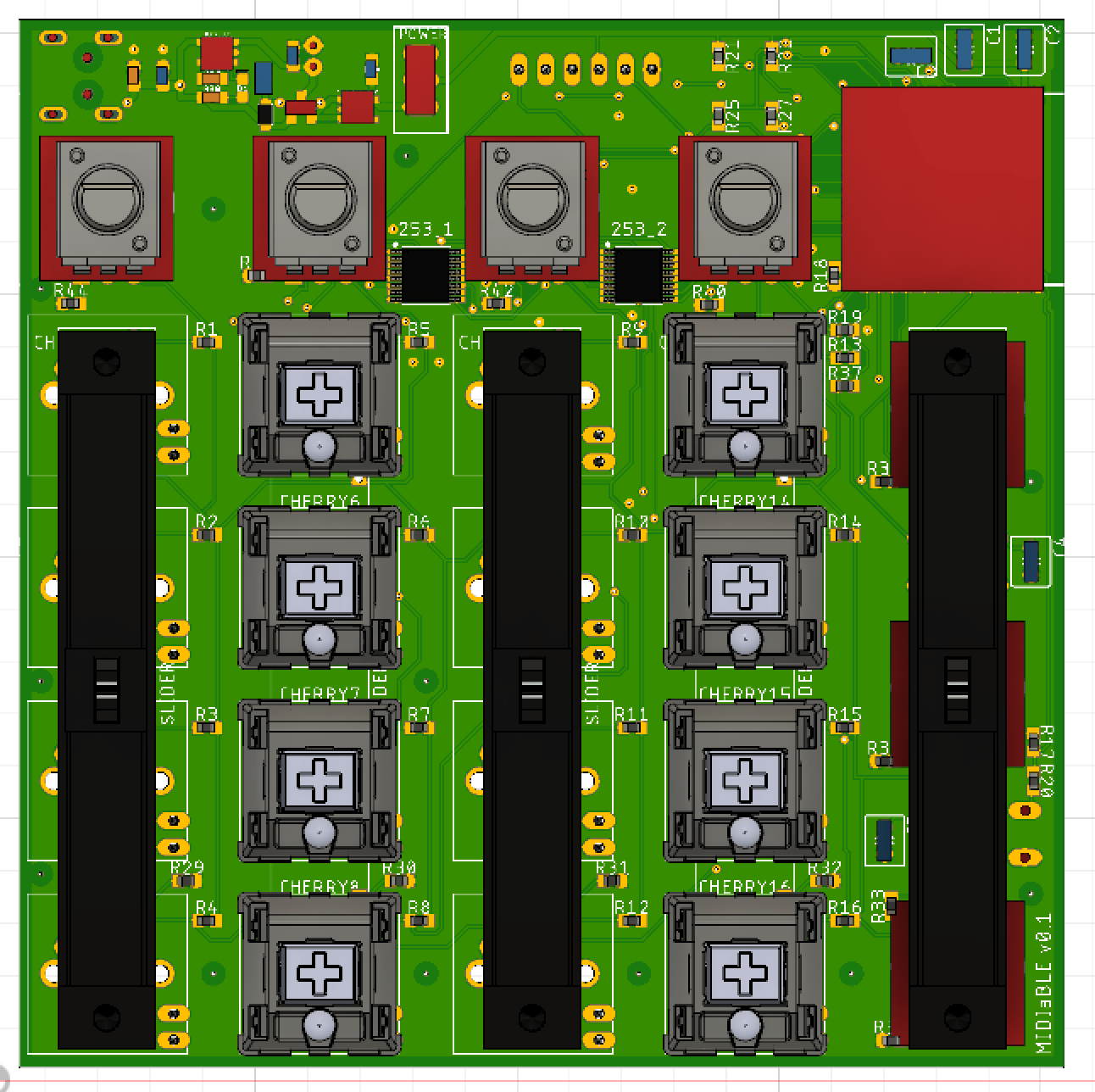
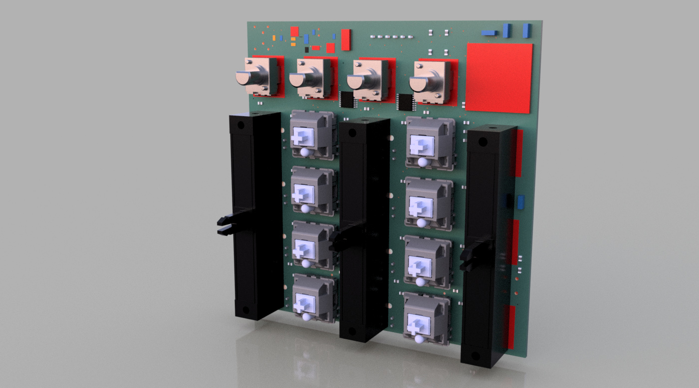
I’m still working on 3d models of all my major components, but here’s what it looks like right now:
I’ve also taken a new approach to how I assign components. There’s probably a more automated way of doing this, but effectively anything that can be remapped in software, I defer the pin assignments, and only make the pin assignments as I lay traces. This allows me to jump less. It’ll be one more level of abstraction in the code, but that’s what code is meant for.'ve also taken a new approach to how I assign components. There’s probably a more automated way of doing this, but effectively anything that can be remapped in software, I defer the pin assignments, and only make the pin assignments as I lay traces. This allows me to jump less. It’ll be one more level of abstraction in the code, but that’s what code is meant for.
I’m still working on 3d models of all my major components, but here’s what it looks like right now:I’m still working on 3d models of all my major components, but here’s what it looks like right now:
The layout is simplified from my original design, and I’ve designed this in such a fashion that it shouldn’t be a ton of work to expand/contract the design or modify in-place (though as mentioned before, I’d probably reroute and reassign some pins).
One upside to my new design is I’ve got a shift register so I can light up all the buttons. On the software side, the device implements a MIDI receiver so that it can turn MIDI notes into LEDs turning on/off. On DJ systems, they use this method for controlling lights on controllers so you know what items are active.
I’ve got some space left at the top for an eventual rotary encoder.
I’ve got a few smaller housekeeping items to do, plus validate the charging circuit (see this thread for progress on that The Bikeshed Board )
I’ve made sure to add pins for supplying 3.3v post-regulator, so if I wanted to validate this sans supply, that would make a test assembly a lot easier.
I’ve tried to keep component counts low, sizes as large as I can fit, spacing as useful as I can with manufacturability in mind. I’m not perfect, and I’ll certainly need some help evaluating how I’ve made some particular choices, but so far I’m proud of the new version. Even from a maintainability standpoint it is leaps and bounds past the first version.
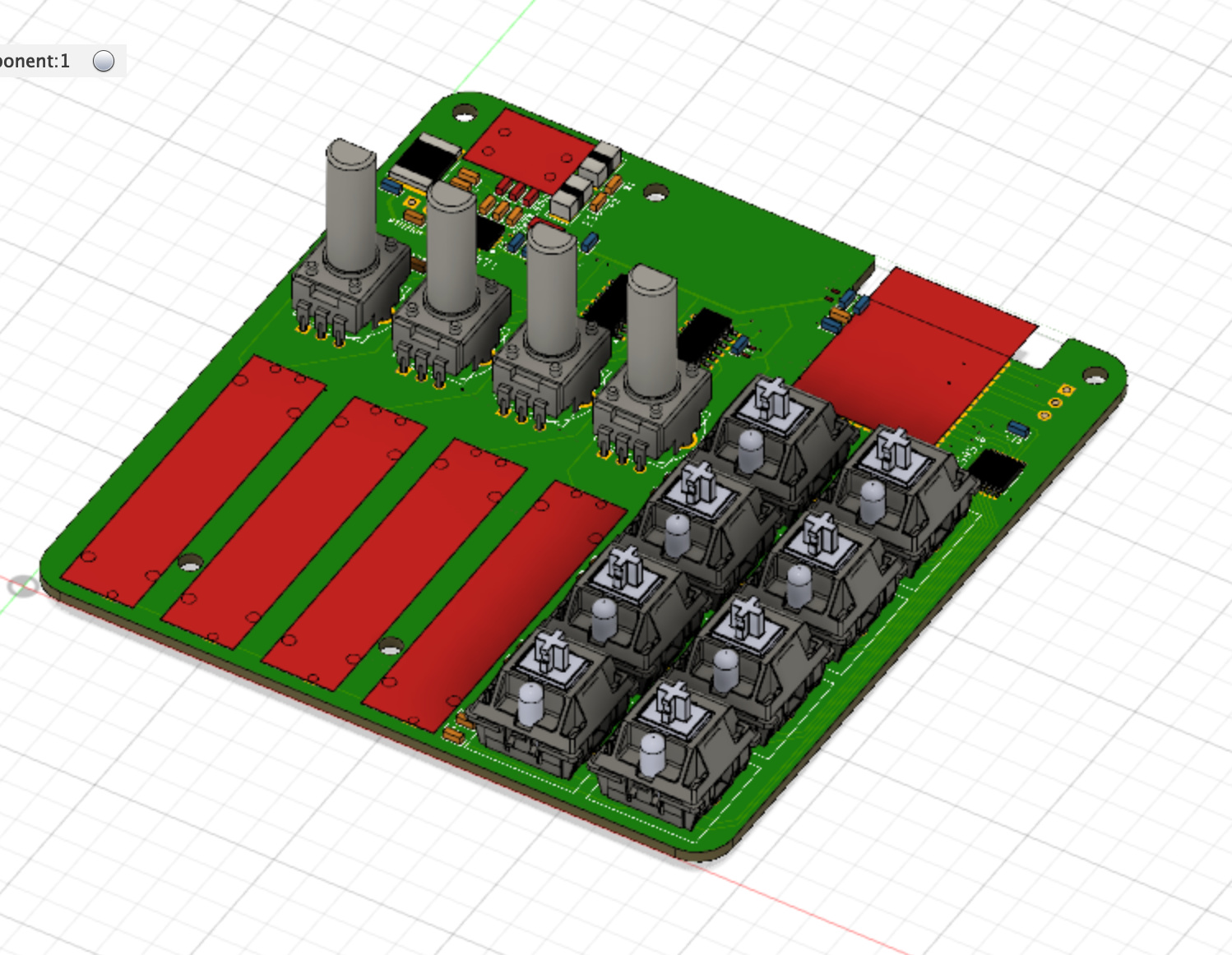
So I’ve done lots of cleanup. Getting the board into 3d helped me fit components and realize what didn’t work well.
I’ve added a rotary encoder at the top, and further isolated some of the local ground-planes so that the regular ground wasn’t coming nearby to ruin the party, the local ground planes for my high frequency devices now have pours under the component, but still only contact through the single shunt with a filter capacitor nearby.
I utilized the local ground for my charging circuit as well, and indicated the isolation in silkscreen. This is a pattern I’ve seen on some boards, where they keep some isolation on their power/charging side, so it seems prudent. The silkscreen is mostly indicative for any sort of bodges, (IE, don’t pull from here unless it is power related).
I cleaned up a bunch of the silkscreen locations, and standardized on a minimum font size that is legible (as determined from other test boards)
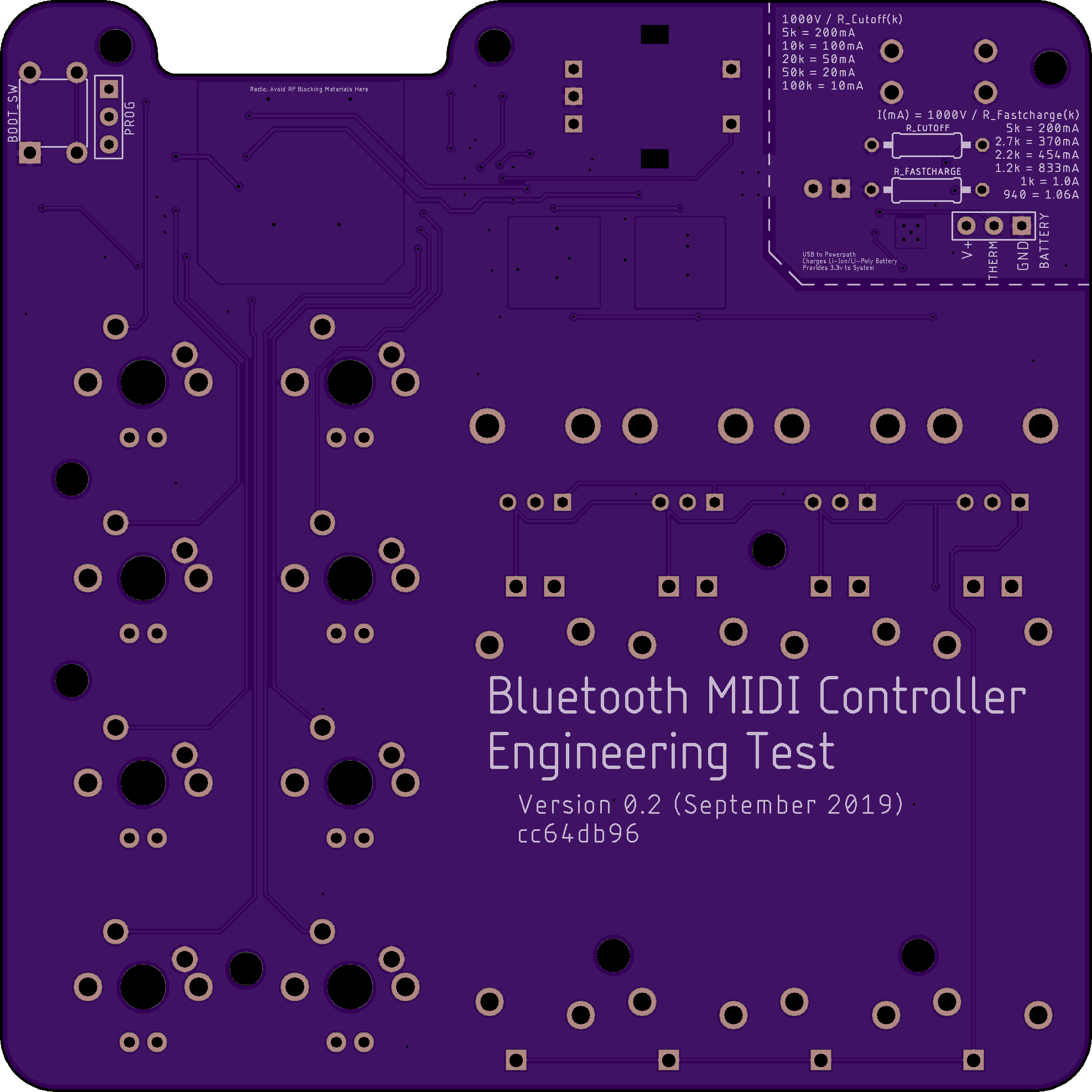
I’ve removed the pointy bits near the antenna cutout (they are now nice and smooth) and I’ve opted for two through-hole resistors for the charging circuit so I can more easily adapt to different batteries. I’ve also added silkscreen with the formula and example battery to charging profile parameters (to help with self-documentation),
The board is slightly wider now (about 5mm wider) which makes it a square 100mm x 100mm. This gave me room to spread out the buttons to provide some breathing room for the keycaps.
I realized my linear slide potentiometers, while probably fine, didn’t have plated holes (I put just regular holes) for the mechanical connections. Those have now been plated to allow me to solder them in place.
I found a bunch of tiny dimensional errors that, likely not critical, were incorrect, so I adjusted those to clean them up.
I’ve also added the boot mode button for programming.
All the components were re-numbered so that they follow a nice flow (and are roughly in the order of if you were soldering by hand and wanted to validate the circuit as you went along).
I refactored some of the mounting holes to give more options for case creation.
I’ve sent a prototype of these off to get things rolling.
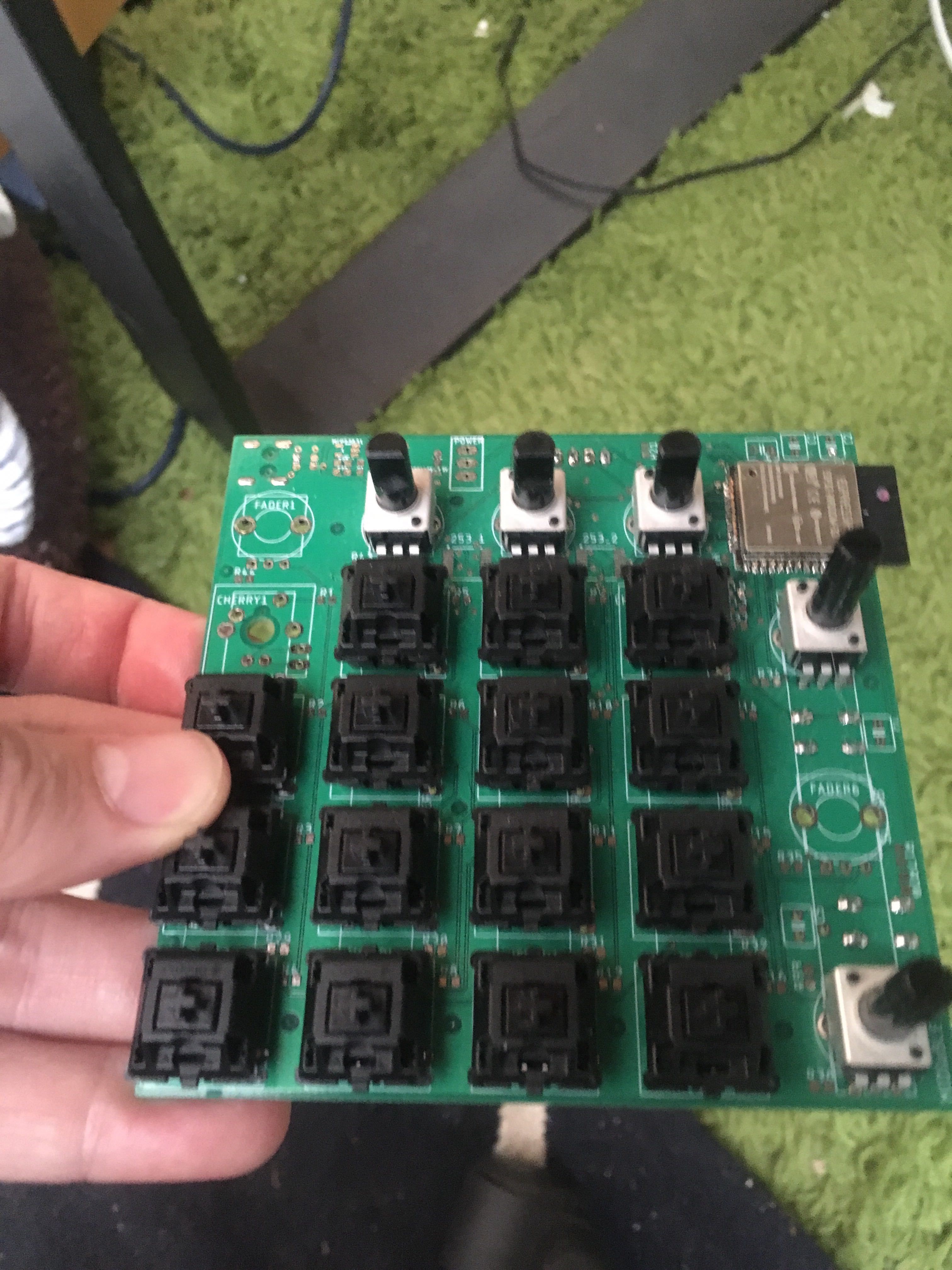
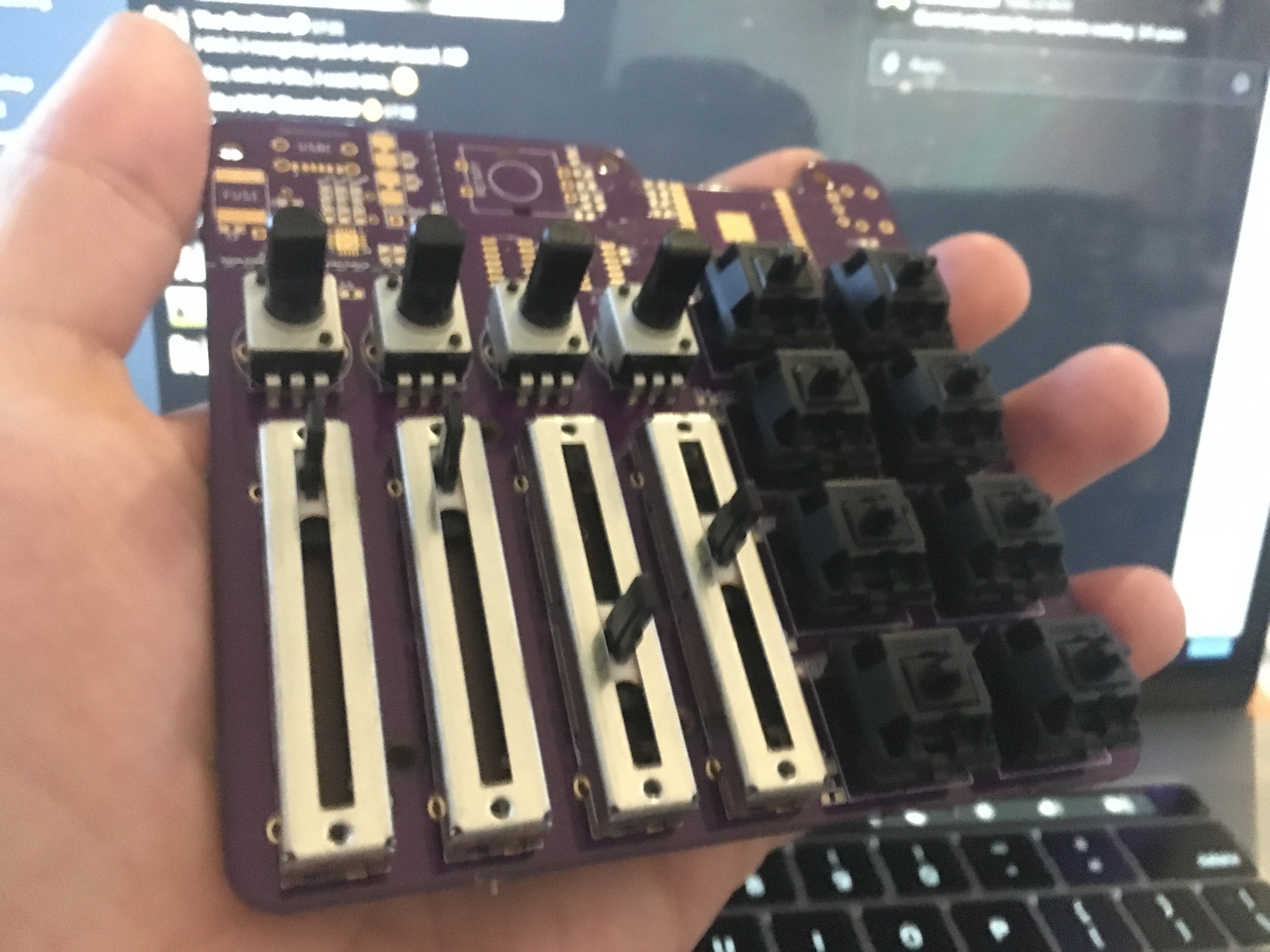
It arrived, and I couldn’t help but dry-fit a few components.
Now to build this bad-boy out and see how it works!
For an idea of how small this thing is (it is meant as a travel item)
looks awesome!
I got a chance to assemble the SMD components on one last night. To my dismay, the voltage regulator just sat there getting real hot, and the output voltage was wrong.
I figured I messed up the power circuit, so I popped off the ESD diodes, which were the only part not tested. No change.
I popped off the voltage regulator, which isolates the system power pins from the power management portion. This let me hook it up to a different 3.3v power supply and throw a multimeter in-between to measure current. It was drawing over 1 amp!
I went back to the data sheets, and poured through my schematic. Turns out I swapped the VDD/VSS pins on my two ADC chips. I sliced through those legs to disable them and my current went back down. It is still higher than I anticipated (around 100ma) but still not bad.
I made a bodge to swap the pins on one, but destroyed the other pads in the process of trying the bodge on the 2nd ADC.
After programming the ESP (and figuring out I really do need a reset pin, or at least the auto-reset circuitry). Originally I figured I’d just jump the pin, since I only need to program it once in production. But I really ought to build it into the board for programming ease (and maybe just not populate extra parts on build)
At the end of the day, I got all the buttons working and some analog inputs.
Now to make some changes.
After getting everything working that I can on this board, I did a test with an 850mAh battery. It wasn’t a highly controlled test, but it at least let me know my ballpark. With an 850mAh battery that probably wasn’t 100% charged, I got 6.5 hours of active connection to a laptop and still had a buffer of about .2 to .3 volts before the cutoff voltage. I’m missing power management code and a second ADC, so this really only gives me a ballpark. I’ll ultimately size my battery based on my power efficiency and my expected battery life. I think 6-12 hours of somewhat active runtime is around the range I’m shooting for.
While I have a low-battery indicator (thanks to my power path manager) I would really like a better sense of the battery level. To do this, I’d need a battery fuel gauge (a coulomb counter). This is essentially a device that goes on one of your battery lines and measures how much energy comes in/out of your battery. I’ve chosen one with an i2c interface because I already have i2c lines for my ADCs. Extending my i2c lines was pretty easy.
I’m currently targeting using this chip:
https://www.mouser.ca/datasheet/2/609/ltc2941-1270779.pdf
I’ve already implemented in the bluetooth low energy battery profile service, so all I’ll need to do is periodically query the fuel gauge and update that value. There is an alarm pin, but given my draw is very small, I think a periodic update will be just fine.
I’ll probably make a warning mode for low battery that flashes everything to try to get attention in case it is nearing low voltage dropout…
I’d say this is feature creep, but if this is to be reliable, I feel like knowing your battery level is important.
This morning I sent off for a new prototype board with the new battery fuel gauge and the fixes from my first engineering test. Tonight I got my rotary encoder working (probably should have validated that before sending off the next board) but at least it worked without issue.
What hasn’t been tested so far is the LED output and having the 2nd ADC on there, but otherwise it all works so far, and I now have rudimentary software support for all my inputs.
Next step will be a race between building out a high fidelity test, and designing an initial case for this. Luckily I have the board in Fusion360 so I can design with the constraints there.
And here it is hooked up to Traktor

OK i want one, looks friggin great!
Aw thanks, @Lukeo!
I’ve got my next iteration of the board in the mail, so you should see a full-functionality dress rehearsal on that soon. I still think I might increase the width a little to allow for larger knob caps and to give a little space between the sliders. Doing that would dramatically increase the PCB cost for small runs, but ultimately I think it is worthwhile for the final product’s sake.
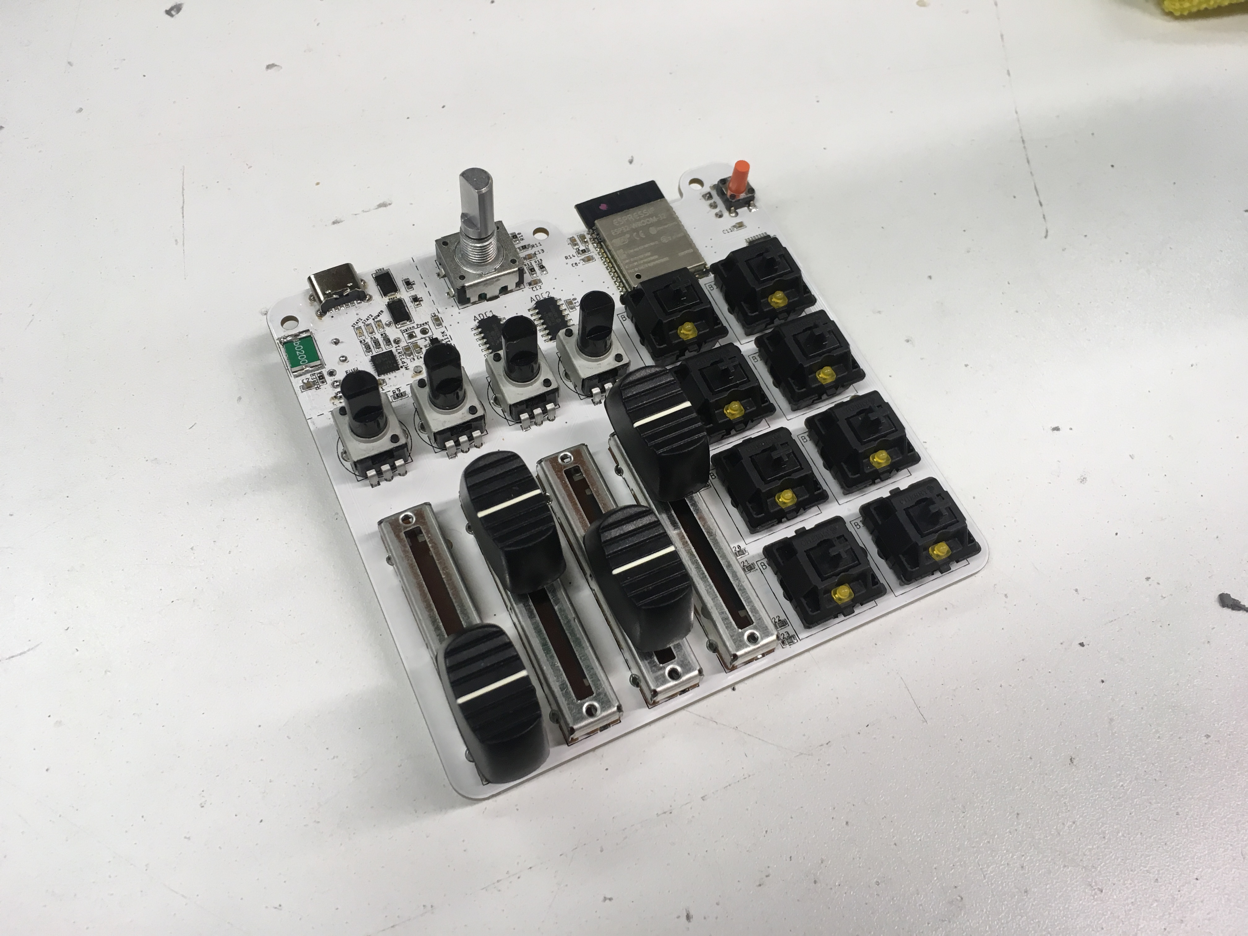
The latest revision just came in from Seeed studio ( www.seeedstudio.com ), and this time I opted for PCBA (which is the PCB creation, plus assembly). I didn’t populate the entire board, I just wanted to try it out, kick the tires, and see how running some parts that they have in-stock would work out.
The boards themselves came out really nice. No mouse-bites on the edges (they are fully routed, you don’t see tabs left where someone clipped the board). Overall, I love the quality. This time I did white, just because I like the look over green, but I’ve now tried nearly all their colours. I’m thinking white or black for a production run at this point.
Each board came nicely packed in bubble wrap to protect it, and the solder joints were great. There were some slight little ‘Kling on’ bits of solder that wiped off by hand, so I guess one takeaway would be to maybe take a quick brush and do a once-over if you were to get them. In retrospect, I wish I had them populate more components, but I also am still iterating on this board. I think I might be getting close to my final design.
Seeed ran a promotion where they covered a lot of the assembly costs. That’s what put me over the edge for this one. It really helped me figure out how the process goes. I need to spend more time on my PCB documentation so that it is more clear where each part goes. They ask you to provide a documentation pdf and an smd placement file for a pick and place. For short runs, they don’t use the pick and place, as the setup probably costs more than just doing it by hand. My pnp files were fine, but my documentation files weren’t that clear for the specific components I was asking them to place.
They emailed me with a picture of the board, a description of what they were trying to figure out. One quick email later where I was able to mark up the image to guide them on what I had failed to be clear about and they were on their way. I really appreciated how good they were at helping me out.
I’ve so far really appreciated seeedstudio for my prototyping. Most of the parts I’m using aren’t in their open hardware list, so in interest of time (it takes them time to buy parts they don’t stock, of course), I left those off. I’d be interested to see how the whole process goes once I do a full board.
Having gone through the process, I now know what I need to do to make it clearer for assembly. They have great tutorials on their site about the technical procedure, but I think I have a more clear understanding on how to lay out my on-board documentation.
I’m looking forward to building this board, as I think it will be my first full-capacity board (all features working).
More to come after I finish assembly on the first one…
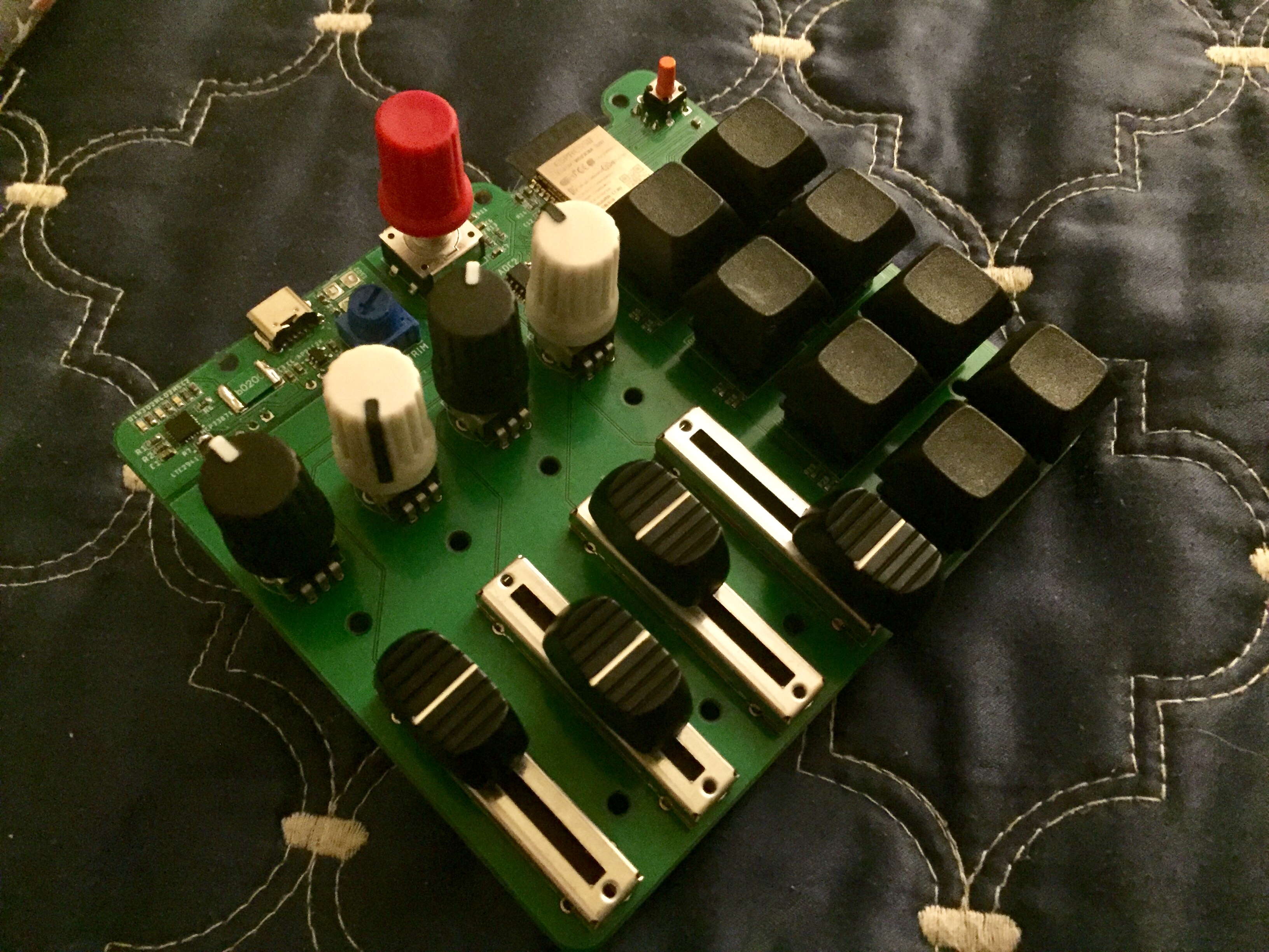
Assembly is completed on this new board.
I have two small errors (just a filtering cap put on the wrong line and one of my voltage dividing resistors is wrong).
I have all channels working (though because of the voltage division, the analog inputs are scaled down), I have battery power-path working, and I have LED output (via MIDI output) working for indicators under the buttons.
Here’s a look at where I’ve mapped a deck switcher and an indicator for which of the four decks I’m on via LEDs.

Wow, I haven’t made a blog post in a couple weeks, but lots has been happening.
I sent off my next revision as an assembled board to both check the process and to see how manufacturable it is. They sent me an email back where they reversed a diode, so I’m losing a few days on that, but seemingly it is coming out well. They have agreed to rework the diodes on the built boards. I’ll need to validate if this was a human error or if this was a pick and place file error on my end before I go into production.
On this run I made the board a bit bigger to allow for better spacing between the analog inputs. The knobs were getting really close together. While this is a compact board, I don’t think going 20% (or depending on how they feel, it might even go up to 50%) wider will be a problem for its intended purpose if it makes a better feel.
After extensive testing, I think I’ve isolated some of my button debouncing woes down to a narrow case. I’m still checking the software to see how it can be fixed, but I’ll write more as I find out more.
I’m starting to consider a hardware debouncing solution rather than software. Software debounce is 99% of the time the right solution in today’s hardware situation. Micro-controllers are so dang fast that you can throw some cycles away, save yourself some complexity, save a little on your BOM, and add some other features at the same time.
The problem comes down to quick presses and latency. As I increase the utilization of my analog input sampling, it is seemingly disturbing my button sampling on the same core. I could try moving the button presses to another core, but that core is dedicated to network communication and I’d rather not muck with that.
If I add my RC+hysterisis to my buttons, I can use proper interrupts so I’m not constantly looping to sample my buttons. This would allow me to have more time for my other functions, as well as have a clear flip/flop accountability on my inputs. Right now I can get into a state where only one direction is reported which can get problematic. Especially software like Garage Band don’t disable an action when any Release signal is received. Instead, it seems they implement an accumulation buffer. So if my releases don’t equal my presses, a note is stuck on.
I’m sure I’ll get people telling me I’m wrong on these assumptions (if you want to see some passionate internet yelling, look up button debouncing), but I’m still in the investigation phase.
I ordered some Pogo pins to see how those work, and I’m looking at how to utilize those with a test fixture. Because I intend to sell this unnamed MIDI board as a kit, I want to make sure that even without all the components populated that it should work as expected.
This video has been an inspiration for a testing fixture:

My current idea is that I can design a test fixture that can:
If I want to make this extra awesome, I’ll build a rPi to administer the tests, drop a bluetooth dongle on it and have it do a bunch of tests that also validate the input functions over bluetooth. If I do that, I’d also like to allow it to do a burn-in test where it runs a sequence over time to ensure that it is nice and stable and getting the midi sequence I expect.
If I add an rPi as a test controller, I can also script it to upload a firmware to validate user-upgradable firmware. If I do that, the first upload would probably a self-test firmware where it is designed to inspect itself, but also include the firmware upgrade code. The rPi would then update the firmware OTA at the end of the self-test and perform the production test, then the last step would be to repeat the same step after uploading the same firmware again. Its a bit overkill, but it makes sure I can have extra testing on my board, that I test all production features, including OTA updating.
I’m getting a variety of switches to both have options, as well as feel the difference between them.
Some of my recent decisions to widen the board come down to knobs that I’ve chosen. They are a bit wider than normal knobs, but they come highly recommended.
I’m considering shipping with DJ Tech Tools’ chroma caps:
They are a bit more expensive, but anything that the end user interfaces with directly I want to feel great. This is a tool for passionate people, so I want to do right by them.
I’ve been slowly investigating a website (oh man, I hate making websites) and honestly, I’ve gotten nearly nowhere with the website.
I’ve also gotten some of the bikeshed boards built. While that’s not strictly a BLE MIDI board, it was the test-bed for most of my power subsection, so getting that validated across multiple batteries and conditions has been quite validating for nearly the same circuit that I have on the bikeshed board.
I’m working on how to package up these kits. Ideally it’ll be easily recyclable packaging (thinking all-paper right now). Packaging for an SMD kit is important since it is easy to mix up or lose small parts.
I have a laser cuttable prototype for these and I’ll probably cut a few on the laser to see how they would work. I’d love to do a pulp thermoforming as a prototype for the midi controller but maybe out of scope for now.
So in documenting my failures:
While my part says 5.1k and is in the OPL database, lookinig further into the part, it is indeed mislabeled and it is a 1.5k resistor. :facepalm: I’ll have to specify another resistor
I didn’t ground my VREF- signal when I simplified my voltage dividers. This caused my ADCs to go haywire as the negative reference wasn’t tied to ground (but not quite floating due to internal chip stuff)
I mistook a 100mΩ for 100MΩ resistor. I’ll fix the problem and maybe I’ll get my fuel gauge working.
Even with the wiidening of the board, I still think the layout is a bit tight with the nice potentiometer caps installed. I’ll probably widen the board a little more. The vertical spacing is now nice. Widening the board will also open me up to other options for my slider caps. I don’t really want to widen the board too much both for cost and size considerations, but even if I widen it a bit more, this will still be a small controller.
Here’s an in-progress shot of one of my recent builds.
I don’t know if this is too late to make a difference, but a fun technique for prototyping is to laser cut or 3D print your PCB. You can laser /print the drills, too, and place your through-hole bits on top to get a good feel for how they all fit, or you can 3D print your sliders and larger components right on there as well if your footprints are complete with models.