BLE MIDI kit dev blog

Hi all. My last big dev blog was the Ukulele build log, so I figured I’d start up another.

At the beginning of the year, I decided on a goal to sell something by the end of the year. I didn’t give myself many parameters, and I could probably cheat, but in my heart I know the sort of things I want to achieve.

  1. I want to create something new. Doesn’t have to be something completely novel, just at minimum a new design or flavor.
  2. I want to sell it, or at minimum, be set up to sell it.
  3. I want it to be something that people want.
  4. I want it to be something that multiplies my efforts once designed.

There’s some other touchy-feely sort of things that I don’t really have words for. One thing that would satisfy this requirement is to make a kit. First I was thinking of making travel ukulele kits, but the design I started down proved to be a bit too difficult and needs some refinement. That project isn’t dead, but it is on the shelf for now.

The other idea I had from the start was a DJ midi controller. I considered making it a USB midi controller, but after discovering the ESP32 (or really, just convincing myself to take the plunge) I think I’ve decided on a Bluetooth Low-Energy controller.

I did some initial research; and for some of the touchy feely reasons, I’ve decided to go with the esp-idf sdk over an Arduino stack. There’s some good technical reason for this too, but it is mostly that I want to get closer to the hardware, and while Arduino is great, it isn’t very mature for the chip.

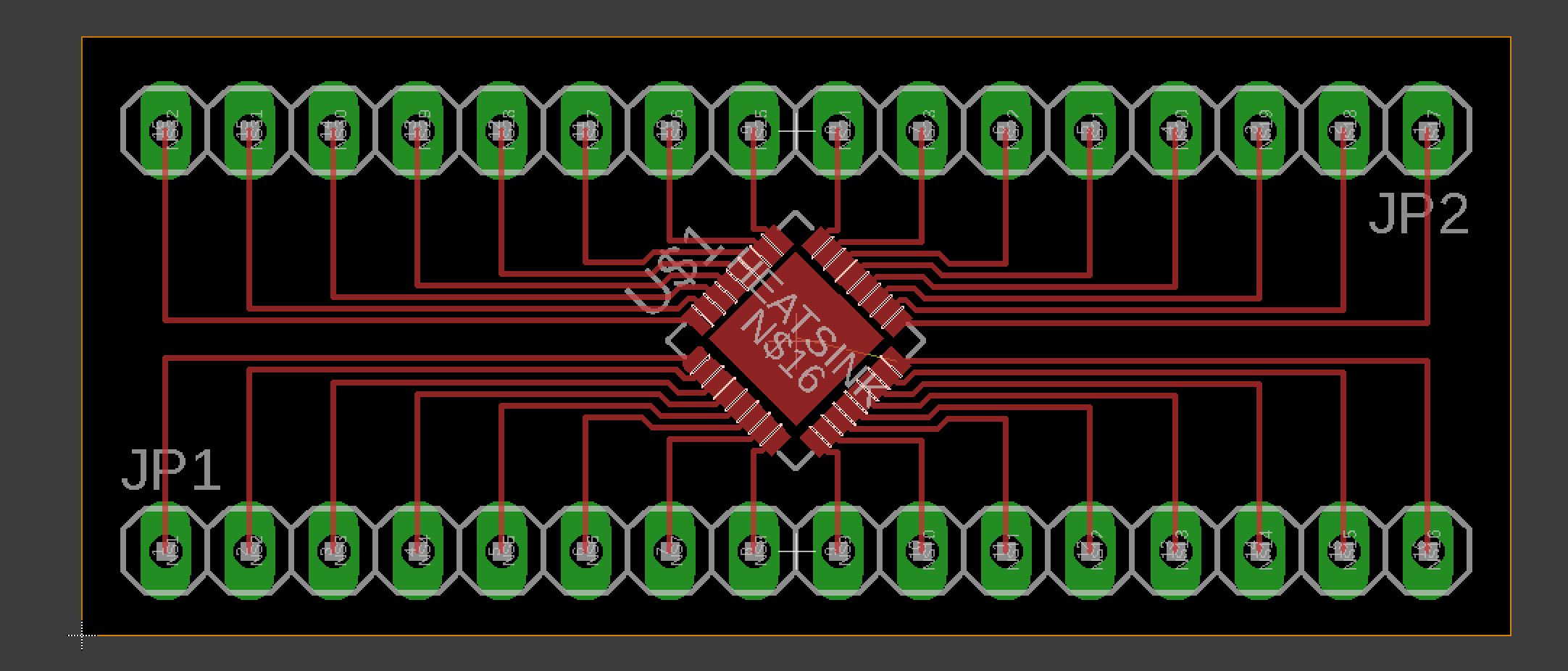
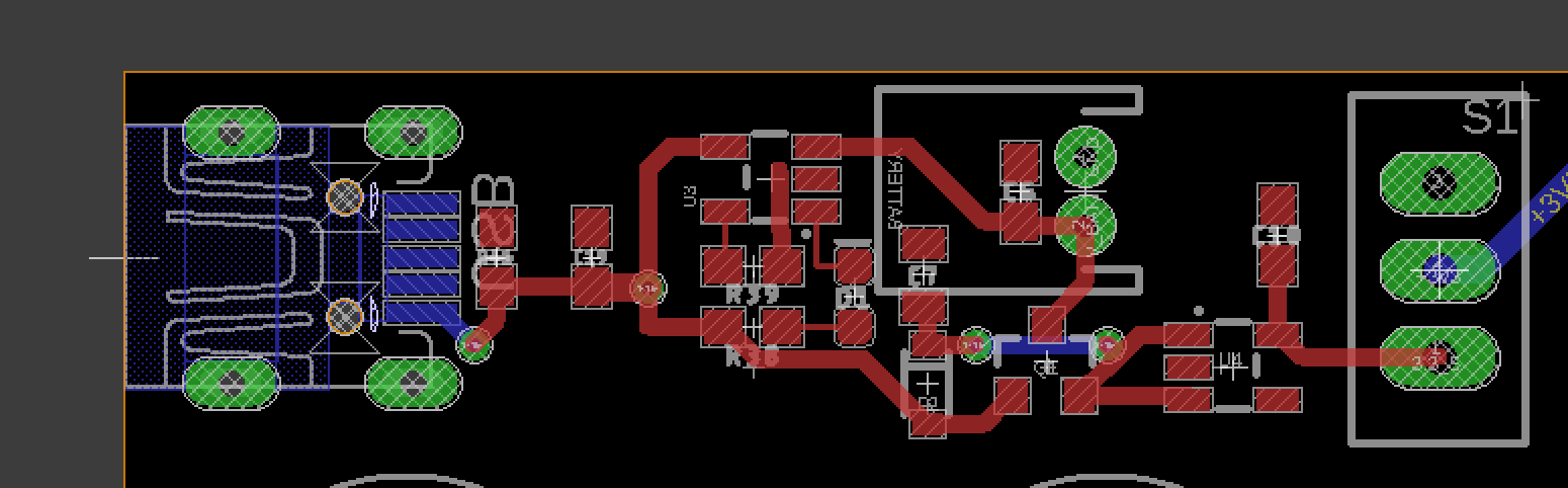
I also found out that the ADC on the ESP32 isn’t the highest quality. I’m only processing human input, so it probably would be just fine, but I took the opportunity to also grab a few dedicated ADC chips while ordering some ESP32-WROOM modules. I designed a little breakout board for those ADC chips and sent it off to seeed studio and should get those back soon. They were FAR smaller than I thought they would be, so this should let me try my hand at SMD soldering as well as give me something to do prototyping with.

For a prototyping board, I’ve picked up the ESP32 Thing board form Sparkfun. This has been a joy so far, but compared to the reference board, it threw me when it had a 26mhz clock rather than a 40mhz.

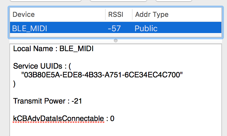
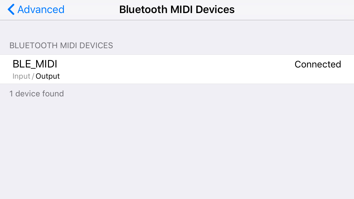
Now that I’ve got a dev board and my toolchain compiled, I’ve gone ahead and played with a bunch of examples in the esp-idf repository. All but one compile and flash out the gate, and it appears that the one closest to what I want to achieve works well (though I’d need either a phone/computer side app or a second ESP32 dev board to test it).

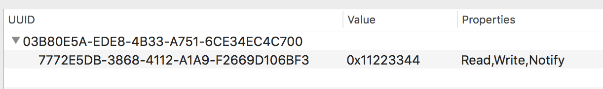
I’m now diving into the BLE MIDI spec. These two links should prove useful for anyone else diving into similar stuff:

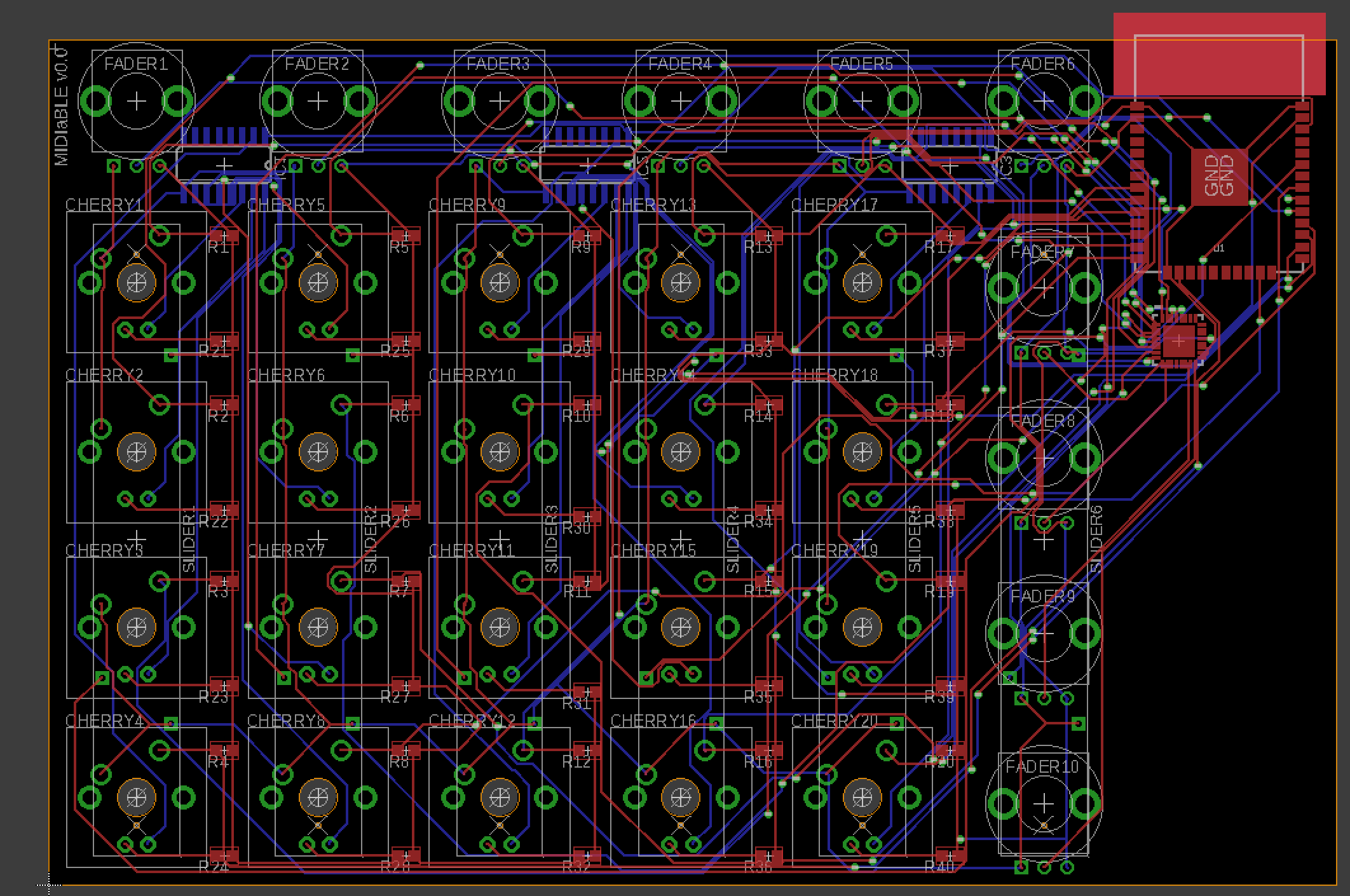
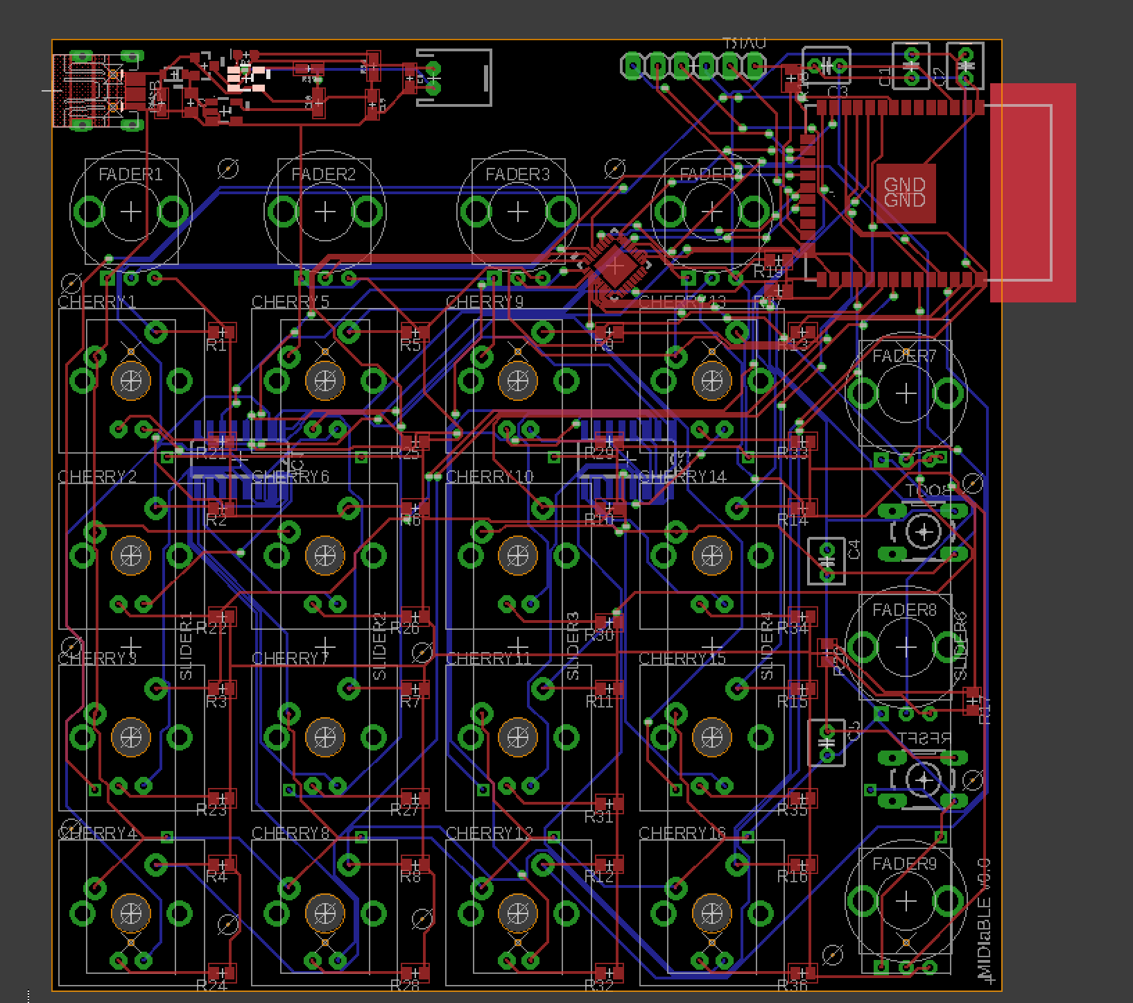
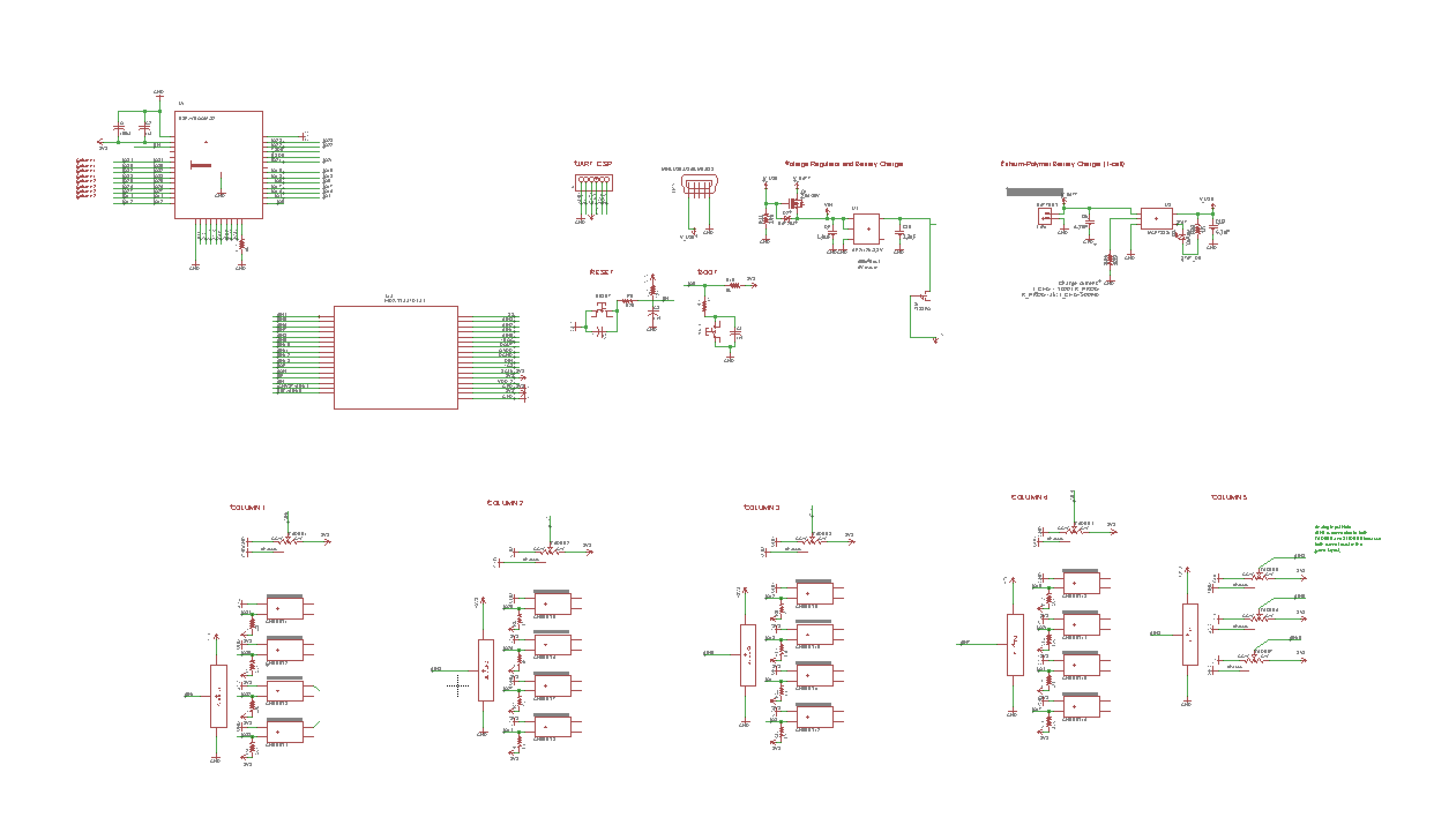
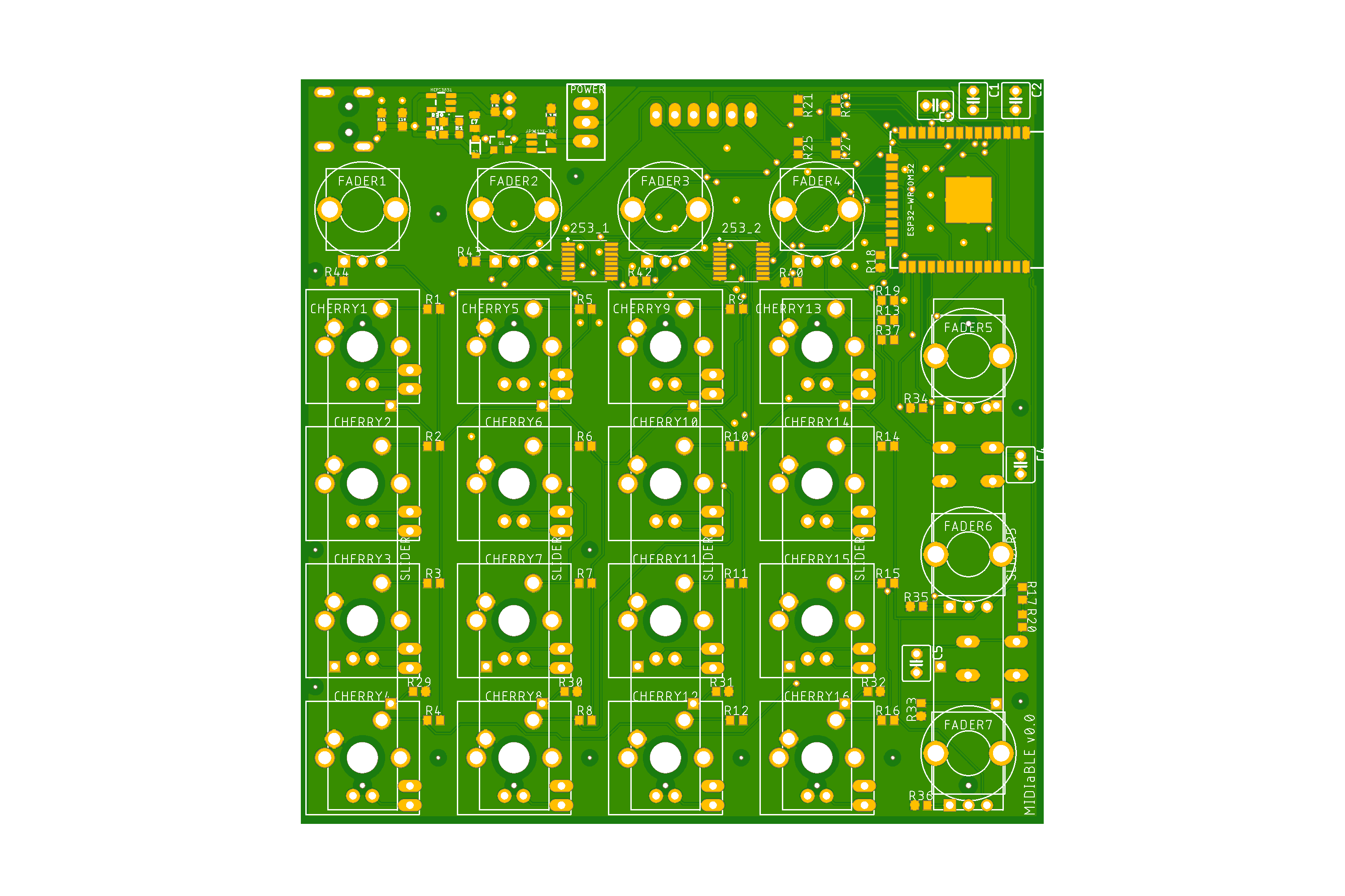
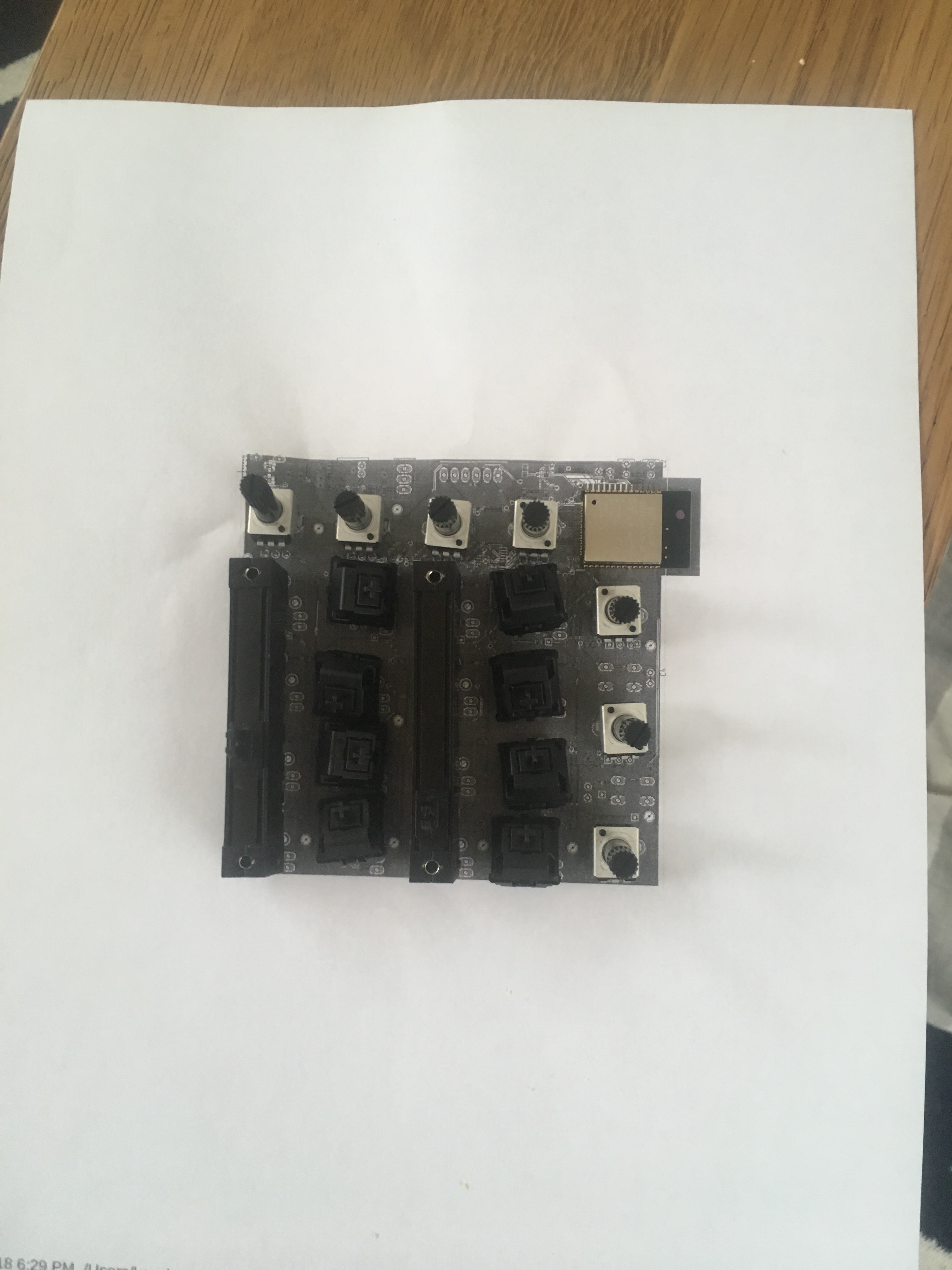
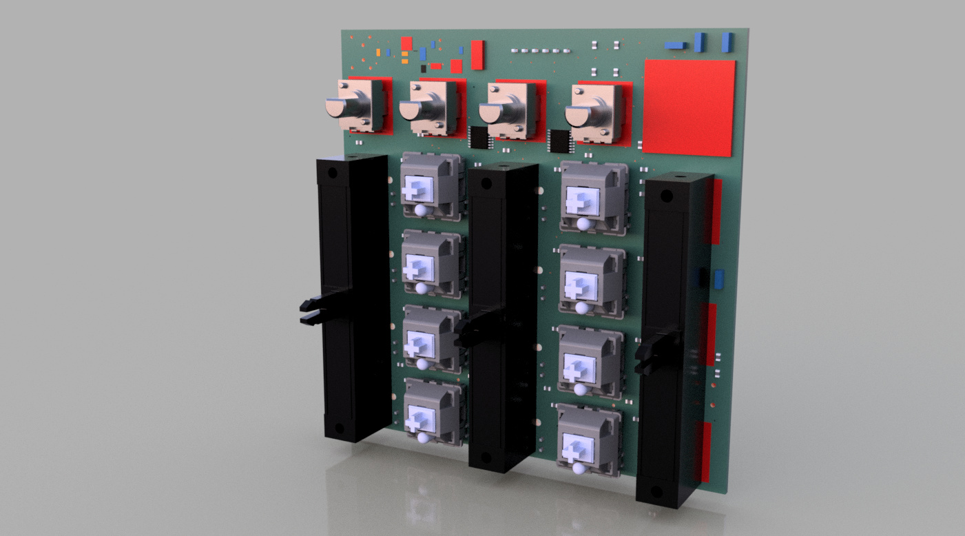
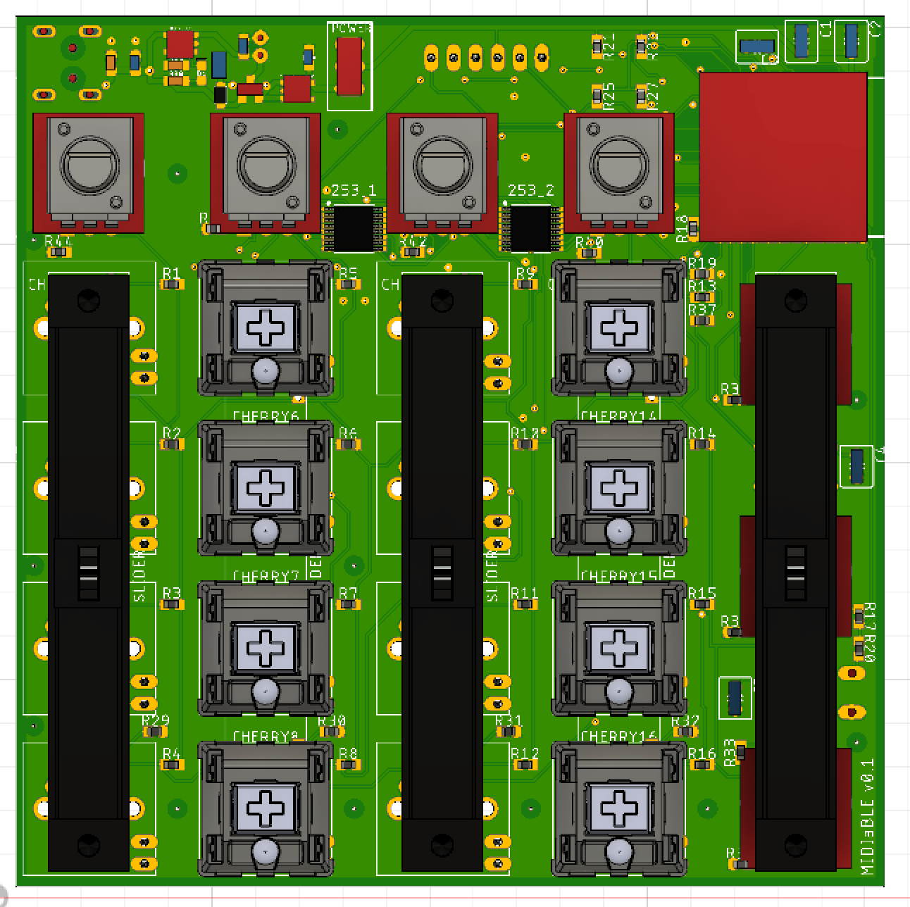
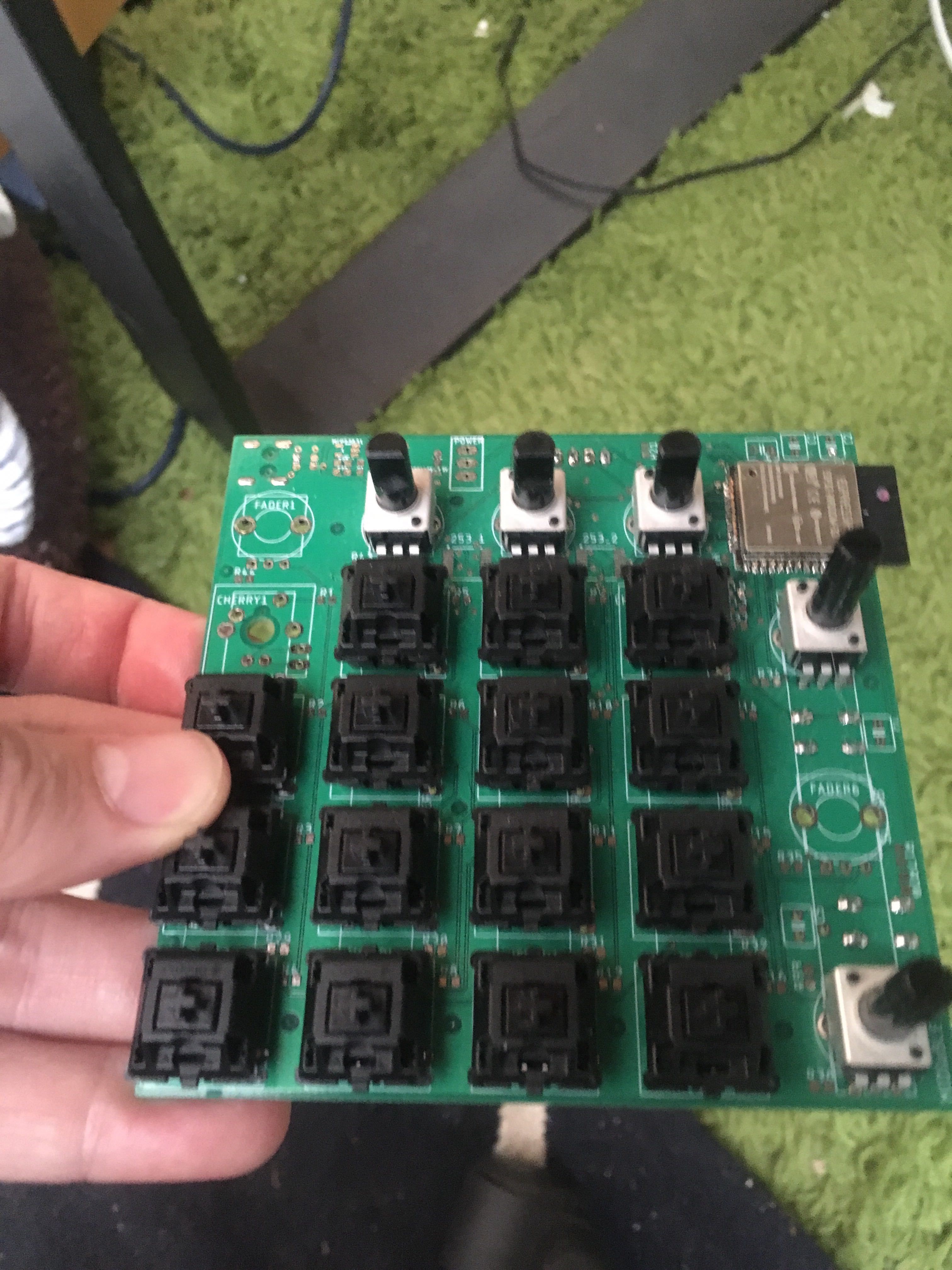
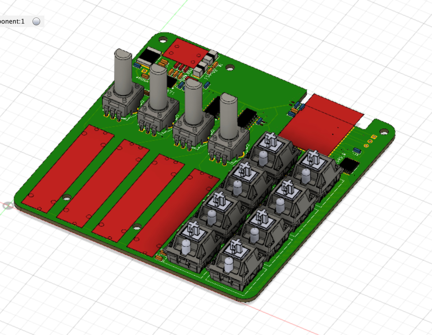
This weekend I was thinking about my design. I want to make this into a kit for DJs, but I also want it so sound mixers can use it for software audio levels. The input controls are a bit different between the uses, but very similar, and all the supporting hardware is the same. Instead of making two kits, I’m thinking I’ll have a layout on the board that is a bit modular so you can solder in either linear sliders, fade pots, or buttons. It won’t be entirely modular due to physical and input constraints, but I’ll try to make it so you can build a variety of configurations. I haven’t exactly figured out how, but I’m also considering adding if possible some way to auto-detect which parts are populated to auto-configure your device.

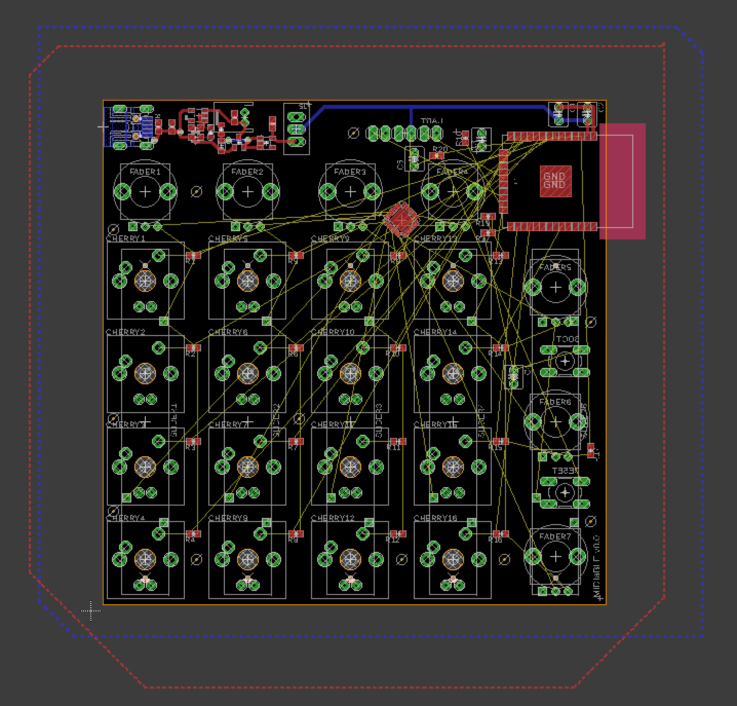
My plan is to design the circuit board in Eagle and use the Fusion360 sync to provide holdouts for an enclosure. This will allow people who buy the kit to design their own enclosure. Part of this came from a desire to have a mid-century modern inspired DJ controller, but it seems like the perfect way to allow anyone to make whatever enclosure out of whatever material(s) they want.

This is more of a brain dump of a bunch of ideas and progress since I didn’t think to start this earlier, but I look forward to keeping everyone updated with progress here.

I welcome comments along the way, and I hope this post serves as use for others. I’m sure I’ll make mistakes along the way and hope to share those too.

3 Likes

This is my breakout board for the ADC, I forgot to add that to the first post, I’ll add a photo once I have the physical part. I hope I did it right :).

1 Like

Well, tonight has been pretty successful. After finding the Gatts Table Create Demo, things went pretty quickly.

I got the Service and Characteristics matching the spec first (not sure on value, but the UUIDs are right).

Then I got advertising correct. After some research, I had too large of a payload since the UUID is 128 bits, so I had to remove signal strength and then advertising started showing the primary service.

I can see the device showing up in Garage band, but for some reason it doesn’t show up in the Midi devices panel, but I’m not sure if it is supposed to show up here. I can connect, I get a packet from the app.

Next I need to start implementing the service protocol now that the advertising is working.

1 Like

After a couple days of banging my head against the wall, it works! I was referencing just the wrong memory for the send command, I also made use of @lukecyca’s awesome debounce library providing a queue of debounced button presses:

Here’s me showing that it works (I threw the battery on there to show there’s no trickery through cables).

My circuit board for the ADC should arrive on Tuesday, and I’ll need to now get out the old breadboard to start roughing out a circuit. This is exciting!

2 Likes

I got back into the circuit design and have done my layout. The layout allows for either a column of buttons, or a linear slider with a fader slider at the top.

All controls are optional, so as a kit builder you’ll be able to have only the buttons/sliders you want.

Additionally, I’ve added LEDs for each of the switches, so you’ll be able to optionally illuminate them. I’m probably over-doing it by intending to use a variant of the 596. Driving a single low current LED is probably plenty done by a 595. I’ll end up ordering these and doing a prototype first just to make sure.

After talking to one of my friends that I am targeting this for, I also replaced one column of buttons with additional fader pots. This is a happy coincidence in that it makes it so I don’t have to use any special boot GPIO pins. All the pins I’m using should be ‘safe’. I wanted to avoid multiplexing so that I can get proper external interrupts on the buttons for minimal latency. The ADC I’m using had just enough pins. In fact, now that I’m writing this, I could re-use the conflicting linear slider analog input and have one left over.

There’s still a few more signal lines to hook up, and I noticed that the 596 does not have an Output Enable pin on the diagram (probably why my first circuit board forgot those, gah!).

Here’s what I’ve got so far:

Also, I haven’t figured out power (that’s likely the empty space) but for the first version, I might do my own first pass at duplicating a known circuit, but put it behind jumper pins so I can optionally just use a power module off the shelf.

3 Likes

I’ve been putting a lot of time into this one. Probably more than I should :-/.

Over the weekend, DHL delivered my breakout board for my ADC chip. It is quite small, so I’m hoping this doesn’t prove too difficult to solder. If it does, I’ll have to scrap that chip and go for something a bit larger.

Once I get this chip on a breakout board, I can validate that it works how I expect it, I’ll write the firmware to validate my assumptions. Hopefully there isn’t much to debug on this side of things.

After looking up how much it would cost to print this PCB, I’ve decided to scale it down a bit. If I could assume I was right I wouldn’t feel too bad with the prices I was seeing, but given I don’t know how this will work, I’d like something that I can grow into. Scaling it down means removing some buttons, which is also good because I need a few GPIO pins back for ICSP and some SDI chip select. i’ve decided to remove a row and a couple faders. This still gives me up to 5 channels of mixing; 4 of them with fade, or 4 channels, all with fade and 3 extra fade (plus a bunch of other possible combos). Removing one of the fade over the columns let me put the ESP32 into the board a bit more, and removing a column let me get the full width down to 100mm and the height is now 100mm. While this will be a smallish control panel, nothing says you can’t have several of them. Being under 100x100 means I can print them at seeedstudio for quite cheap.

After lamenting over what I’ll do for power, I realized that the sparkfun board I have is exactly what I want. I can plug in USB, run from lipo, charge the lipo battery, and run from the lipo. Also, sparkfun is open-source and they use Eagle, so i grabbed the Eagle .sch file. They break out the functions quite nicely so it was just a paste in. Board layout wasn’t nearly as easy.

I still have a few signals to wire up for SPI, but this is the board layout as-is.

I’ll need to spend a bit more time doing some hand-layout of the power components and beefing up the traces.

2 Likes

Work has continued for several days trying to clean up things, readjusting layouts, checking connections and pins, etc.

I got some great help on the circuit board design slack channel with regard to layout. I’ve taken many of these suggestions and incorporated them into my board, specifically for the power circuit.

Since I intentionally have some physical separation between the power/battery circuit and the signal area, I also drew a holdout area to keep the autorouter from draping a signal trace across my power lines.

Next I’ve built out power lines that go directly to my ESP32 power filter caps. I don’t know if this is necessary but my idea here is that hopefully I can achieve the cleanest rails by having large traces direct to these caps.

Also, to help isolation, I’m doing a GND fill on both top and bottom layers.

I’ve also simplified it a bit further. While I’d like LEDs, it adds another 1/3rd the number of elements to solder, causes me to have surface mount parts on the back side (shift registers) and quite frankly, complicates things for my first board. I’m leaving the solder pads in there in case I want to have the odd LED under a button hand-wired up to something, but it is a feature that I’ll leave for the future.

Maybe I’ll play with having the signal connection also drive the LED rather than them be microcontroller processed. That would make them simply light up when activated which would still give good feedback. By removing the second SPI device, it frees up a bunch of GPIO that can now be ‘safe’ GPIO pins (ie; not a lot of functionality conflict depending on what is happening, ie boot.

Here’s a look at the full board

And here’s a closeup of what I’ve done with the power section. It allows for USB in, to charge a lipo battery, and to operate on either the lipo or usb. It is literally a copy of ESP32 Thing by sparkfun

I also massively cleaned up my schematic because that was getting hard to read:

Things left to do:
Check all my connections
Finish wiring off my SPI lines from my ESP32 to my ADC
Add an override in case the power circuit doesn’t work
Make a protoboard mockup of my ADC to see if that works as I expect it to.
Check all my connections again
Add some silkscreen art
Check a third time.
Do a final check with the community (make sure I’m not crazy)
Send it off.
Hope it works.

3 Likes

So the ADC didn’t work out like I hoped, and in reality, it is probably too small a trace for a kit.

So I’ve done some validation with the onboard ADC and it looks like it’ll work. The ADC onboard is a lot faster than the Atmel, so I’m not so worried about it anymore. It is also 12-bit and so even if I need to do some remapping I’ll have enough resolution to hit the MIDI output (I believe 7 bit if I recall correctly).

One downside is that top and bottom end of the ESP32 ADC has some dead spots. Beyond that it is a pretty linear response curve. If I can fit my signal into a .1v to .9v range I should get about full use of the potentiometer wipers. I can up with overly complicated resistor nets to solve this when really it was a much simpler problem
With some help of @lukecyca early on and @Jarrett coming in with correcting me I have a better simple solution for finding my range. I’ve implemented that in the design and I’m pretty happy with the board so far.

The last big things to verify is if my assumptions are right with hooking up UART and the multiplexer. The multiplexers seem pretty straightforward and I can manually hook up a chip for UART to match my design to make sure I can program one of these once assembled. If I can’t program the chip once assembled I’m pretty much doa unless I were to make a pre-programming board, but I want to allow for in-circuit programming.

If this ever goes full-on kit, I intend to make a preprogramming fixture so at least a base version can be installed.

I did a quick calculation on the number of possible layouts that can be achieved and it is over 12-million. But in reality there’s only a dozen or so that I expect to actually see built. But since I’m using cherry switches, I do expect people to get creative with different buttons (for instance, clicking buttons for some and soft for others.

I’m building out my parts list for mouser so I can send in an order for my initial trial boards. Once I validate the last two major unknowns that are work-stoppers if wrong, I’ll ship off a batch for test boards.

Then I’ll turn my attention to refining software.

This is getting exciting; but it has taken about 10x more time that. I initially expected.

2 Likes

I’ve exported my BOM and come up with suitable parts in Mouser’s project manager (just a glorified saved shopping card). I now have a rough idea what one of these will cost me; and it still is below most MIDI devices I see out there, so win so far.

I’m narrowing down real fast into my prototype 1. This is what it looks like so far:

Assuming this works, this is the spec:
Up to 5 channels of linear sliders
Up to 7 channels of faders
Up to 16 low-latency “note” buttons
USB Powered (micro USB, no I didn’t go for USB-C, but I did think about it, maybe a future version).
In-circuit programming
Supports charging 1 cell lipo battery
Runs off of 1 cell lipo battery (won’t be included in the kit, since the capacity vs physical space is more of a personal preference)
Also just added pinouts for all the LEDs under buttons so you can do extra stuff with them (maybe make a second board that does light patterns :smiley: Mostly I’m leaving that as an option to the user,

Some of the up to conflict with each other, here are a few sample layouts:

  1. 4 linear sliders, 4 “note” buttons, 4 faders (might be good for mixing, with a few effects)
  2. 5 linear sliders, 4 faders (might be good for just a pure mixing board with no effects)
  3. 2 linear sliders, 8 “note” buttons, 7 faders (might be good for a 2-up DJ setup)
  4. 16 “note” buttons, 1 slider, 4 faders (where you want to maximize effects or triggering, or even use with a keyboard HID firmware (say for trigging special keys, keyboard shortcuts, setting volume, etc).

I’m in the final stages of pre-order verification. I’m nudging things around to try to make them the best. I welcome any and all suggestions/concerns at this point.

1 Like

I’ve further refined little bits here and there, mostly cosmetic (but one functional issue). There’s more bonus features I want to add and cosmetic cleanup, but they are all low risk.

I’ve shipped off prototype validation 1 (v0.1) to seeed studio. They have a $1/board deal for up to 100mm x 100mm for up to 3 boards. In total with shipping I’m in for a tad over 35 cad for 3 boards.

Because this is a kit, I’d like to eventually do a medium run at oshpark; as I hear the board quality is excellent.

1 Like

Looks awesome! A few questions, I haven’t been paying close attention:

  1. presumably this needs a computer or other host device with built-in or dongle support for BLE? Is there a dawless use case? Maybe a sister device to “break out” the Bluetooth to old-fashioned circular MIDI?

  2. Can it run off USB when there’s no lipo connected?

1 Like

Yeah, any computer with BLE (Bluetooth 4.0+) should support this. So far I’ve connected with my iOS device as well as my 10.13 Mac, but windows 10 supports BLE as well. Once connected it is just like USB midi.

A dongle to go from ble to USB/din would be cool, that might be a future project if this goes well.

Yes, no battery is actually required. The kit won’t come with a battery so by default it will be USB powered. You can plug/unplug at will and it shouldn’t turn off if you have a battery attached. I am trying to make it as flexible as I can since it is intended as a performance device.

Also, the LiPo/Charge/Supply circuit is directly taken from the ESP32 Thing board. One upside of open-source boards is that they solved it for me.

I’ll be interested to see how it goes over the long term, but that board has been doing well for me so far in testing.

I’ll be including their contribution in the distribution materials (as well as other contributors to the project).

I got my components in and printed out (on paper) my circuit while I wait. This gives me an idea of how everything will fit together.

I’ve set this up as a 2-up dj console with 2 sliders, 8 buttons, 4 top faders and 3 side faders (though i’d probably just omit two of the top faders if I were doing this as a 2-up)

It is tight, but I think it’ll work nicely. These are certainly smallish controllers, but I’m intending for them to be very portable; drop one in a bag and go.

I’ll start gauging interest on a large run once I have a final cost and once I’ve validated the design. I’ve already found a few cosmetic things that I’ve changed, but I’m tagging things in git so I know what I’ve sent.

1 Like

I’m starting to get my 3d models into the design; these will be used in both enclosure generation as well as documentation images.

Here’s an early rendering.

Adding a GL orthographic render, I think I like this more:

4 Likes

This looks really professional!

I don’t claim to understand the use-case, but there something that came to my mind while admiring the rendering…

Those potentiometers or rotary encoders at the top are quite close together. If you haven’t already, I suggest checking that there is enough spacing for the knobs that go on to the shafts. I had to redo a front panel because of this once…

There is also a usability aspect of having knobs very close. In my last project, I glued all the knobs and buttons and stuff on a printout of the circuit board and played around with them to see how it will feel. I ended up spacing the rotating knobs further apart so that my fingers have space to go between. Really depends on how you plan to use it.

(If you haven’t gotten the knobs yet, 3D printing a rough approximation of their shape of them worked well for this purpose)

1 Like

Thanks!

I’ll likely be turning my own knobs, but yes, they are tight but I’ve ensured clearance between each knob.

In reality, if I were making the above layout, I’d probably just omit the knobs above the buttons to give more room in-between the channel faders. They are potentiometers rather than encoders. I have ordered both center-detent and non-detent ones depending on how the user wants it.

The primary use is to use it as an input device for either DJing or mixing, but the flexibility of it is intended to support lots of layouts. For instance, if you just wanted a 16 button hotkey keyboard, this can function as that.

It is a small board for a couple reasons. Primarily, due to price. Once you go over 100mm x 100mm, the price goes up fast. The second reason is I want these to be very portable. If someone needs more buttons/sliders, there’s nothing saying they can’t run 2 of them (they could even put 2 in the same case).

You are right though, it can be cramped when you populate every piece in there.

1 Like

It has been a long time since I posted…

History

I ended up sending the board off and ordered all the components. Once I got them all and the board, I looked it and basically shat myself with how much work it would be to assemble the board. Certainly not appropriate for my first surface mount project. I lost momentum a bit. Here’s what a partially populated board looks like to get an idea of look and feel.

But the reality is; I’m just not excited about what it came out as. But this isn’t over!

Instead, I’m using it as a reason to change this into something a bit easier to manufacture.

I’ve changed out my software stack a little bit. In the year since I started this project, there’s been some maturity in libraries, and I’m currently on the phase of checking out hardware.

Another thing I didn’t expect is that the slide potentiometers I planned for aren’t in abundance at the space (don’t get me wrong, lots of slide pots at the space, in fact, too many, go use some, but many of them are audio-taper, and almost none of them are 10kohm. I can use different values, but it effectively became a mess). They are also a bit more difficult to get than I anticipated.

Changes

So Instead, I’m going to be trying something a bit different. I want to attempt to design something I can get manufactured where most of the components (pretty much all the surface mount at minimum) are assembled. Right now seeed has PCBA, so I’m going to try that out. I’m trying to use parts from the open parts list as much as I can to make manufacturing easier, and where I can’t I’m trying to find parts that are easy to source.

On the software side, @lukecyca’s/craft metrics ESP32 libraries have been awesome. In the past I’ve used his debouncer, and now I’m considering using his ADC library (GitHub - craftmetrics/esp32-mcp342x: ESP32 compatible library to interface with the MCP342x class of Analog-to-Digital converters). I’ve now gone through 3 ADCs in search of the right one for this project.

Progress

I have some hacked together code so far. It works but isn’t elegant. It does the following:

  • Provides a wifi access point where I can upload new firmware (for OTA updates without internet/servers)
  • Provides a bluetooth low energy MIDI service profile
  • Samples two potentiometers from a MCP3424 and sends control MIDI packets
  • Provides a bluetooth battery status service profile (though does not currently send any real info).

I’ve hooked it up to Traktor (in demo mode) to validate the end-to-end. While my sample rate isn’t great (just need to write that loop, lots of of extra delays in it right now) this is what it looks like as I control it.

Next Steps

I need to break a couple things down in hardware and software, and some need to happen before others.

For instance, one of the paramount concerns I have is latency. Luckily I’ve already got both input and output midi services implemented, which will let me test latency. There are lots of bits with latency I can’t change. For instance, I can’t change the computer BLE software/driver stack latency. From my reading, I know that some BLE stacks are slower than others. I also can’t change the hardware/protocol communication latency. These are all sources of latency I have to live with, but my research suggests they are, at best case, well under normal perception.

Where I can affect latency, so far, is:

  • My button choice (cherry switches have a stated 5ms debounce time, there are some buttons with higher and lower debounce times).
  • My debounce option (while software debounce can be about as performant as hardware, I need to see how busy my app core will be. If it is already too busy, I might have to implement hardware debounce to keep the core more available.
  • My sampling code (just need to implement it well)

Back to measuring, if I can get my button hardware and code roughed out, then I can hook up the logic analyzer, set Traktor to feed back my input to an LED on the controller, and basically measure the delta between the initial state change and when the LED lights up. This will let me determine what the best route is, or at least if a route is acceptable.

More to come soon…

5 Likes

I’ve been refining the code quite a bit, cleaning up rough edges and one crash I had.

I’ve got one button implemented (again, thanks to Luke’s esp32-button library), and since I have different sampling tasks, I now have a ring buffer that can accept commands and orders them into bluetooth commands. Theoretically it supports joining multiple commands into a single command if there is more than one in the buffer, but I haven’t gotten into the case where my sampling is faster than my bluetooth transmission time. If this case were to happen, it can omit one duplicated timestamp and join multiple commands into a single packet.

I’ve also implemented a hysteresis/filter for my analog inputs. This makes it so I don’t duplicate the same value, and I get a micro latch when changing directions to prevent any unintentional bounce back when you let go of or stop an analog control (such as a slider). The latch is on the level of a single value, but it just reduces the extra noisy signal you might get and retains the user intent a bit better.

On the software side, this weekend I was working on providing saved settings for what each button/analog input maps to using non-volaitile storage. I understand that most DJ controllers will allow you to remap buttons, but I figured I should, at least internally, have the ability to do custom mapping on the controller side too.

On the hardware side, I’m looking into power path and charging. I’m seeing that getting a proper charging circuit might be pretty difficult, but at least there are good reference designs. Given that this portion of the circuit would be super useful in a lot of other projects, I’m considering building this part of the circuit first, getting it made to validate it independently, and if I get a good circuit working, then I can use the prototypes as power supplies for other future projects.

2 Likes

Many of you have seen me quite active on the circuitry front. Some of that was to help validate portions of this project, and some of it was to improve my circuit designing skills.

What I’ve ended up with are several boards in the mail, lots of parts waiting for boards, a bunch of great knowledge (special thanks to @lukecyca who keeps furnishing me with amazing insights).

I’ve taken the in-progress version of the Bikeshed board and mapped it to a new version of this project (but not bike-shaped, and only one USB connector :wink: ). I standardized on 0603 or larger, so all the little flea-sized 0402 I’ve scaled up.

I implemented (thanks to Luke’s links) local grounds for my high frequency devices (ESP32 and ADC) and also limited my power supply to a localized path with holdouts and my final filtering capactor for my supply output is nearby (essentially local-grounding the supply as well). This as I’m reading, effectively reduces the effect of the whole ground plane forming as an antenna (both input and output).

I’ve also taken a new approach to how I assign components. There’s probably a more automated way of doing this, but effectively anything that can be remapped in software, I defer the pin assignments, and only make the pin assignments as I lay traces. This allows me to jump less. It’ll be one more level of abstraction in the code, but that’s what code is meant for.

I’m still working on 3d models of all my major components, but here’s what it looks like right now:

I’ve also taken a new approach to how I assign components. There’s probably a more automated way of doing this, but effectively anything that can be remapped in software, I defer the pin assignments, and only make the pin assignments as I lay traces. This allows me to jump less. It’ll be one more level of abstraction in the code, but that’s what code is meant for.'ve also taken a new approach to how I assign components. There’s probably a more automated way of doing this, but effectively anything that can be remapped in software, I defer the pin assignments, and only make the pin assignments as I lay traces. This allows me to jump less. It’ll be one more level of abstraction in the code, but that’s what code is meant for.

I’m still working on 3d models of all my major components, but here’s what it looks like right now:I’m still working on 3d models of all my major components, but here’s what it looks like right now:

The layout is simplified from my original design, and I’ve designed this in such a fashion that it shouldn’t be a ton of work to expand/contract the design or modify in-place (though as mentioned before, I’d probably reroute and reassign some pins).

One upside to my new design is I’ve got a shift register so I can light up all the buttons. On the software side, the device implements a MIDI receiver so that it can turn MIDI notes into LEDs turning on/off. On DJ systems, they use this method for controlling lights on controllers so you know what items are active.

I’ve got some space left at the top for an eventual rotary encoder.

I’ve got a few smaller housekeeping items to do, plus validate the charging circuit (see this thread for progress on that The Bikeshed Board )

I’ve made sure to add pins for supplying 3.3v post-regulator, so if I wanted to validate this sans supply, that would make a test assembly a lot easier.

I’ve tried to keep component counts low, sizes as large as I can fit, spacing as useful as I can with manufacturability in mind. I’m not perfect, and I’ll certainly need some help evaluating how I’ve made some particular choices, but so far I’m proud of the new version. Even from a maintainability standpoint it is leaps and bounds past the first version.

3 Likes