Ok, the nest is nice, but everything else is straight out of the 80s industrial design. I can’t believe it.
So, I’m taking it upon myself to improve slightly, starting with my own apartment. This place has 4 separate zones for a tiny apartment, so I’m certainly not going to buy 4 nests.
The requirements:
I have 240 volt baseboard heaters which run right through the wall to
the thermostats, so I need to be able to switch high current/high
voltage. (This could be easily switched for a control of a low voltage for other people’s houses)
I don’t care about controlling it locally, I want to set and
forget.
A display would be nice, showing current temp and if it was
heating or not, but I don’t plan on doing this on version 1
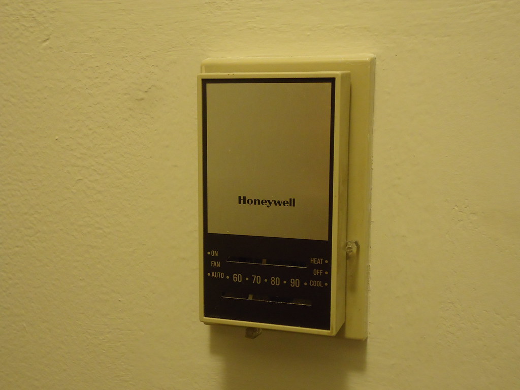
It has to not look like ass [like this][1]
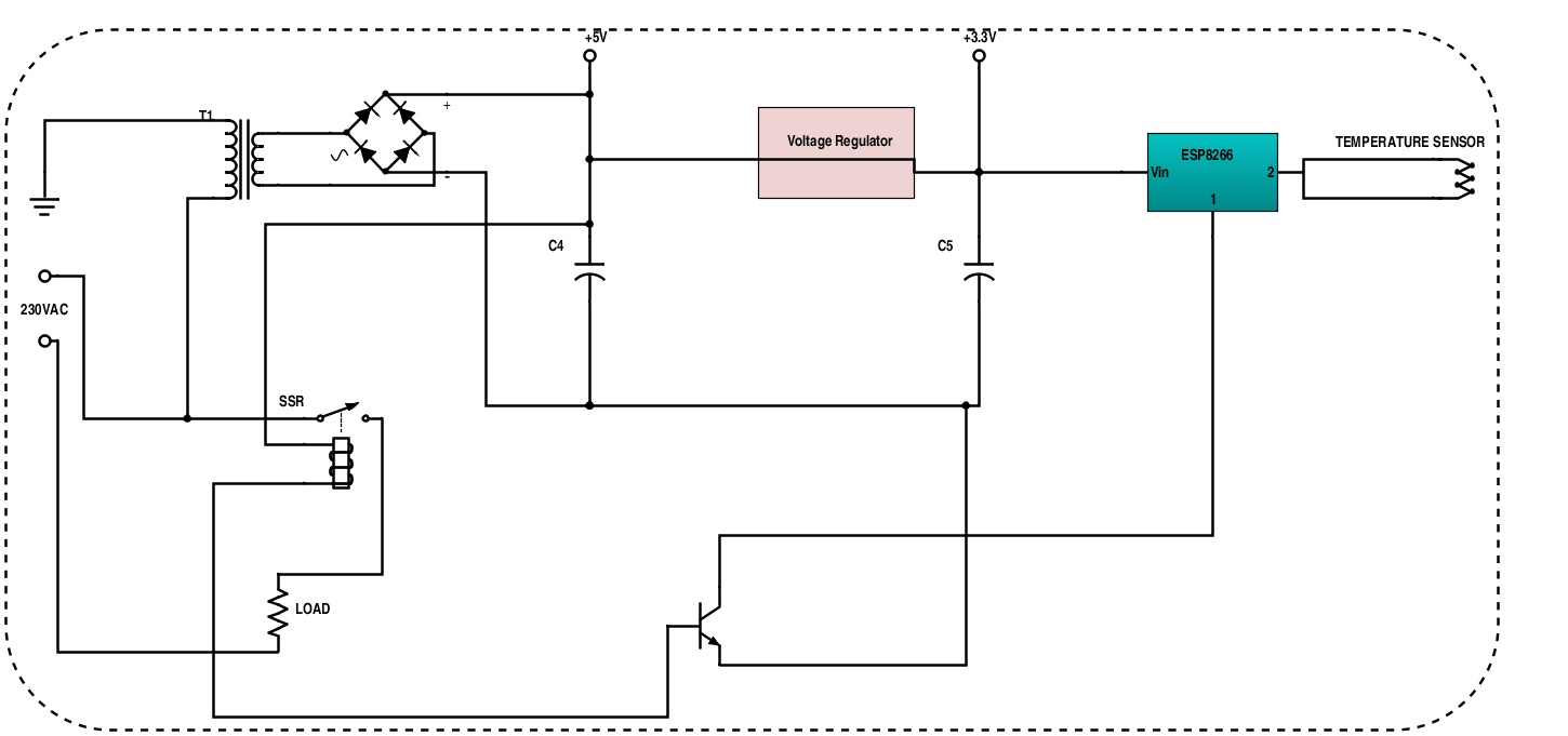
So, for electronics I plan to stick an ESP8266 inside, a step down power circuit from 120V to 3.3V, a SSR to handle the power, a transistor to power the SSR off the 3.3 volt line directly, and a temperature sensor.
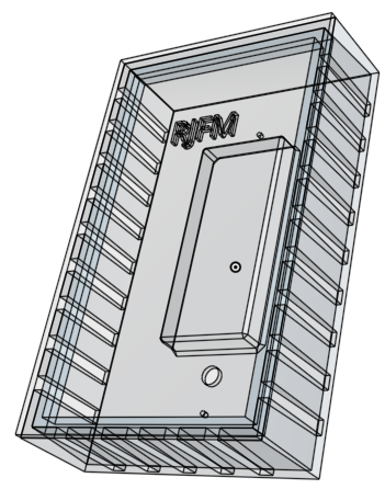
I plan to 3d print the enclosure, and then stick a nice laser cut opaque acrylic cover on top of that. Here’s what I’m imagining, I threw it together in sketchup. The “claws” would go all the way around, they were just a major pain to put in. I think I’d also have them grip on the inside so I could have the acrylic flush. I’d have to glue something to the underside of the acrylic to mesh with the “claws”, likely also 3d printed.
I also tossed together a really basic idea of a circuit diagram of how it would work.I’d just use an off the shelf 120 to 5 volt switching supply, not a transformer like I drew in there.
I think that if you had “claws” all the way round you could end up with unwanted crap/dust in your closure. You could also put your hardware into a smaller box to protect it.
Any particular reason you’re rolling your own power supply? If you can do
it, I’d get a power supply from China instead. There’s like a 99% less
chance of you burning your house down and not getting an insurance payout.
What’s going on with the coil / BJT portion? What’s the intended logic?
Many thermostats don’t have power available to them, expect to need battery operation. Your baseboard thermostat probably only has two wires, the supply wire and the feed wire to the heaters. Take care because it is code to repurpose a black/white 14/2 to run two actives - in Australia you use special wire with two actives in it (like 14/3 without the neutral).
For 24V operation (most things other than baseboards are 24V) you might have 24V supply to run the thermostat but you’re likely to have the same deal, a 24V supply wire (eg RH) and a feed wire to the gas valve/controller/etc. (eg. W/B)
You’d need something to draw the air in to sense air temperature, afaik thermostats protrude to use convection to move across the temperature sensor.
You could have a vented face plate. Or the faceplate could be raw metal to use as the temp gage. Totally green hatting. But isn’t that what this is about?
You could always mount the sensor right on the inside of the case. Several of my thermostats have a small thermistor (I’m assuming) that is glues to the bottom of the front cover rather than being in free air. This avoids needing vents to allow air flow. Your room temperature (nor the response of your heating system) doesn’t change fast enough to need immediate response so the thermal lag of the housing would not be any issue… The one issue is that if you touch the housing with your hand (while adjusting it) the temp will read high till the heat from you hand is removed. Not a huge deal (and your firmware could ignore temp changes while any adjustments are begin made) as you don’t make adjustments that often…
There is nothing preventing you from putting the ESP8266 and relay inside the baseboard heater itself. That way you will have access to power regardless of the house wiring.
Then you would need to sprinkle temperature/humidity sensors throughout the home and have a command and control center that will determine when to signal the baseboards to turn on/off (as well as the extraction fans)
I have a similar need. I have 4 zones of hot water heating. My boiler is modulating but it can’t crank down low enough when only one zone is calling for heat (specially when it is not all that cold outside). This leads to short cycling of the boiler.
There is a feature that (seemingly patented by Honeywell) attempts to synchronize the call for heat so that a call from a single zone is deferred (for a certain amount of time) till another zone also needs heat. I have only seen this available in very expensive Honeywell and Tekmar (funny enough head quartered in Vernon) control systems.
The logic and control system would not be all that hard to setup (though you would need to really watch the errors and exceptions, if the heat doesn’t come on in the cold your pipes could freeze, if the heat doesn’t turn off your pets could die)…
The harder part is a nice control pad that mounts on the wall that allows basic settings, shows the inside/outside/set-point temperatures… That (as Rob says) doesn’t look like ass. Mebbe a touch pad with a nice display. To make the GUI easier any really complex functions could be configured via a web page rather than the control panel itself.
Anyways I have thought about this for sometime but never got started on it.
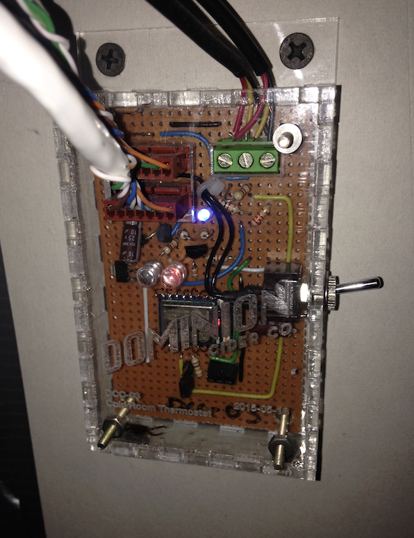
I’ve been using ESPs with a similar circuit to control chiller compressors of various types, including a couple fridges and a 100sqft cold room. I’d be happy to share my notes and code if it helps.
I’ve been using DS18B20 digital temperature sensors since they’re easy to interface to an ESP’s digital pin and you can chain multiple of them to the same pin. I like to use a few sensors placed at different locations so I can see performance of the whole system.
I always mount one sensor right on the controller board, but be careful where you put it. If it’s in a poorly ventilated enclosure with a Vreg and ESP, it’ll be a few degrees hotter than ambient.
I use a mechanical relay, but with an SSR you have the added benefit of PWMing your baseboard heaters if you want. Use some PID control logic in the software and you can have ludicrously consistent temperature for your house!
Be careful which ESP pin you use to control the relay. Some pins are pulled high by default (for example, when the chip is in programming mode, crashes, etc.). On the ESP-7/12, GPIO 4 or 5 are good choices for the relay. You want this system to fail SAFE so I suggest testing some failure modes by deliberately crashing the chip during testing. The watchdog timer can help here.
The switching transistor in your schematic doesn’t make sense to me. You want to switch the base (and use a resistor).
Here’s a controller which has been deployed for about 3 months, although I’m about to replace it with a new-and-improved one soon hopefully!
I posted this at 5:00 AM as I couldn’t sleep. Some glaring omissions It all made sense in my head when I drew it.
Thanks for all advice so far, really solid.
I plan to put only the temperature sensor in the front ventilated area, and the ESP itself will live back behind this plate with the SSR, protected from dust and in theory the SSR could vent heat behind the wall. That’s why I have the standoff inside, to mount the temperature sensor.I figure with a the honeycomb pattern of 3d printing it would provide sufficient thermal insulation from the components in the back (not that they should heat up much anyway)
I suggest you use a relay … less heat dissipation and you don’t need the high on/off rates possible with an SSR. And if you program the ESP to toggle during AC zero crossing then you can minimize arcing
Interesting. I didn’t realize that was a concern. What’s the risk? Does arcing pose a threat to the relay? Safety? Is it just a problem when turning the relay on or also when turning it off?
It’s not a risk per say as the mechanical relay contacts are designed to survive a certain amount of arcing at the rated currents and voltages.
However, my reasons to toggle during zero-crossing are:
minimized EMI
reduced wear on the contacts (ie longer life for the relay)
load sees a “gentler” sine wave rise/fall on the voltage. Otherwise it may be an abrupt voltage drop or rise (like a square wave, full of high frequency harmonics)
Keep in mind that detecting the zero crossing would require an opto-coupler to maintain isolation if you are using a turn-key power supply module or dc-dc switching power supply. If you are building your own linear power supply, you could tap off a signal just before the rectifiers.
And yes, I would do it during both the off-on and on-off cycles
Emergency Stop is another deal and it should take the safety action (such as cutting power, etc.) immediately and not wait for a zero-cross
@hectorh super cool ideas, I hadn’t even considered that. Thanks for input!
I guess I’d discounted a relay due to their loudness (though the old one is loud too) and their high driving current.
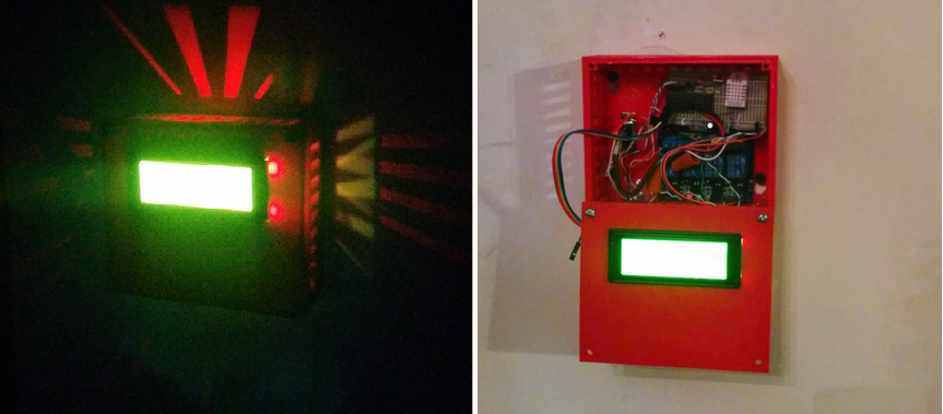
Here’s somebody who’s done it something like this, but I don’t like the look. I was considering an LED somewhere, but I haven’t figured out a way to do it while looking good yet.
First try at 3d modeling. I did this in onshape.
I think I’ll print it and see how it goes. The air fins have an inward slope so they should mate with the matching slope of the connecting piece. Not sure if there will be enough flex yet. Front piece will be opaque acrylic, haven’t decided on colour yet, or if I want to try to be fancy and do a two colour thing or an inlay. First thing first, a solid slab.
Holes and mounts inside are for mounting to my wall and to mount a DHT22.
@Jarrett@wander I am going for minimalist design on this one, I don’t think the EL strip would. I would want any indicator to be barely noticeable.

