Welcome to another YAP (Yet Another Project)
This time it’s a self balancing robot…
I was researching STM32 stuff (blame @Jarrett) and stumbled onto an interesting site…
While not STM32 based the balancing robot caught my interest mainly cuz I had a bunch of the needed parts gathering dust… So I decided to build one and figured I’d document the process here.
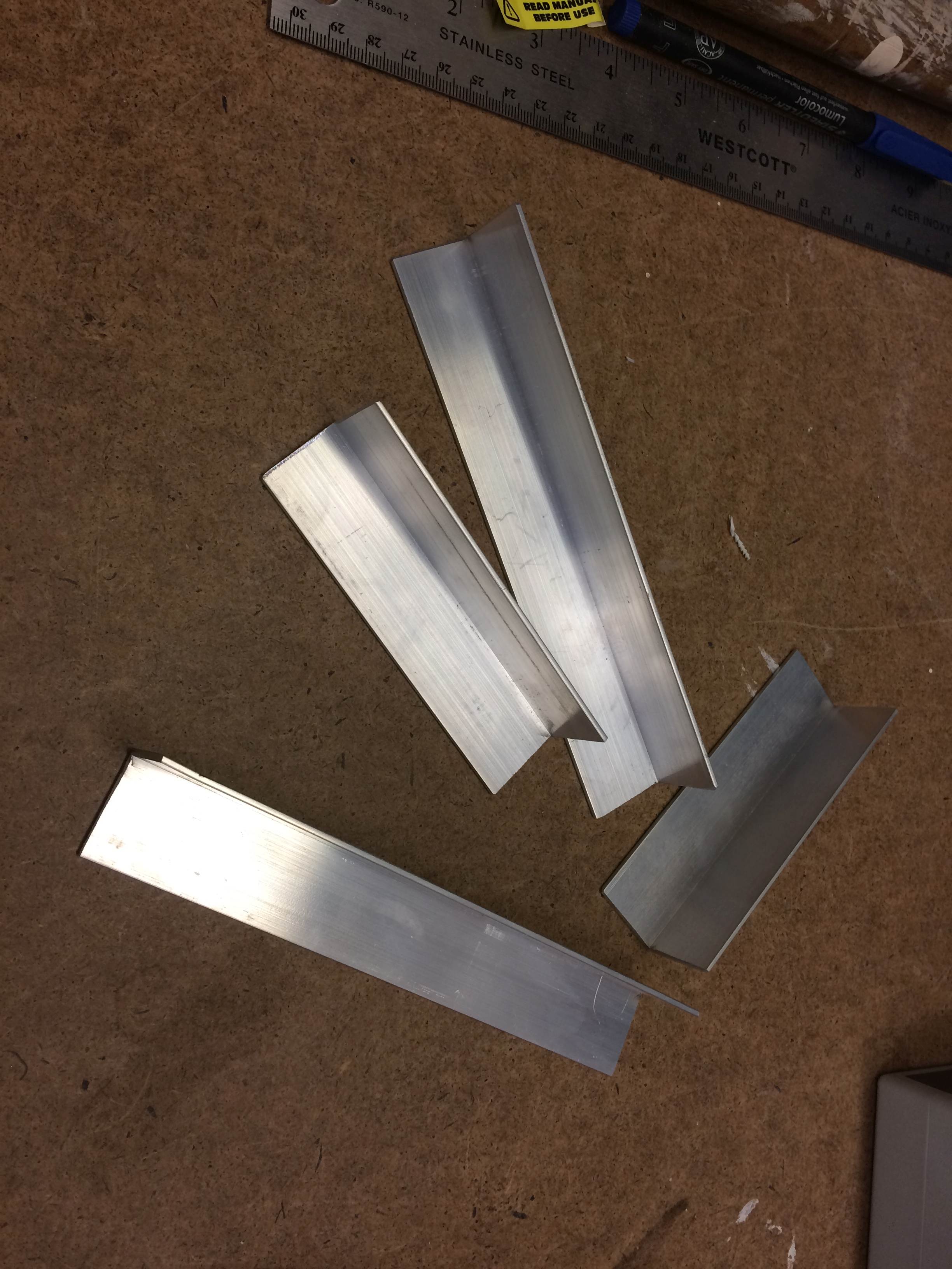
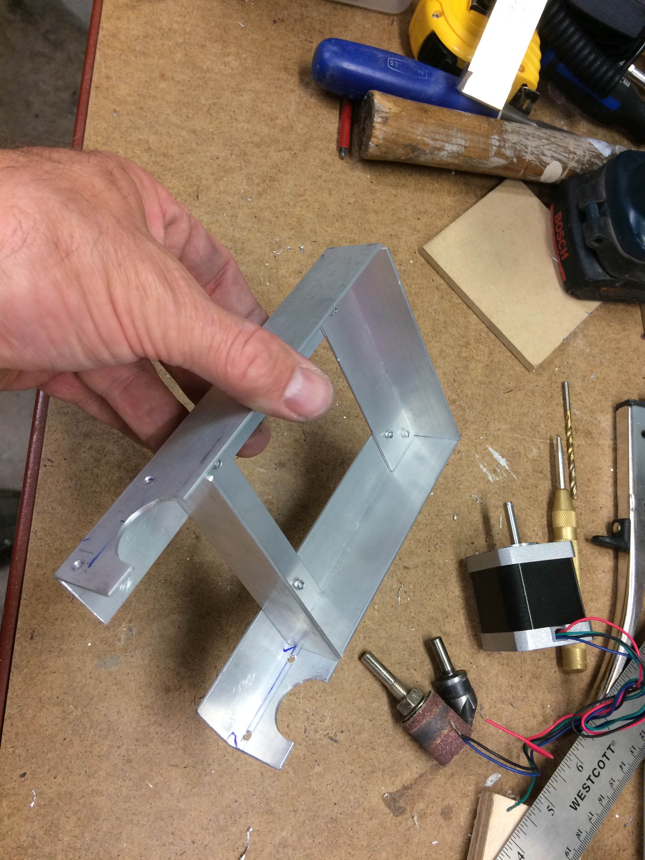
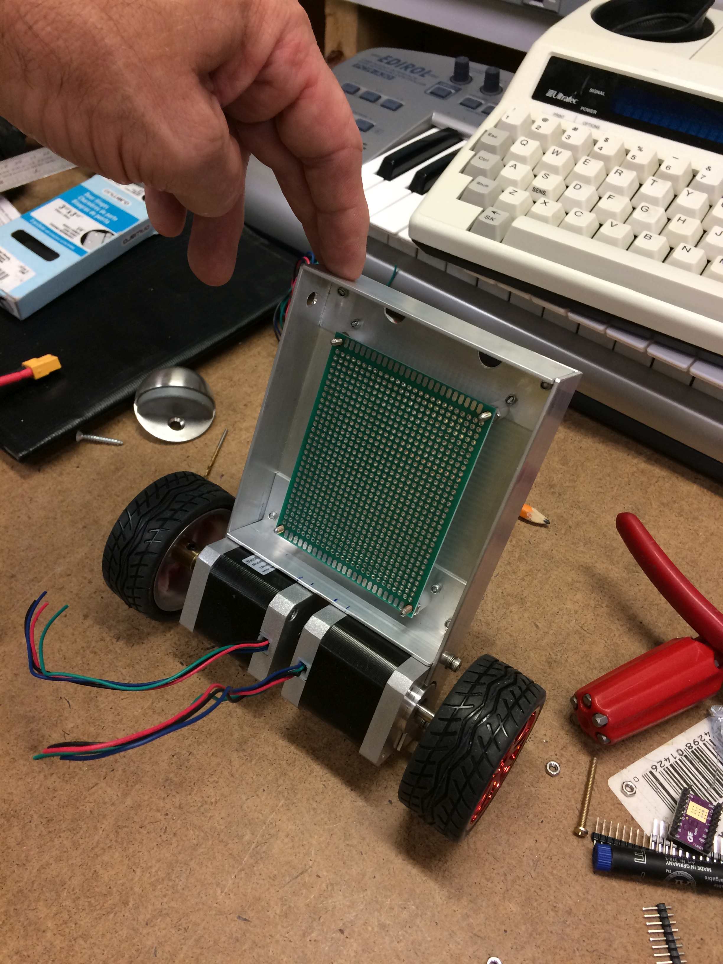
Next I thought about the frame. They used plywood for the prototype but I didn’t have any thin stuff to use. But I do have lots of aluminum angle so I decided to use it. I’m wondering if it will affect the rf signal but it will just be a frame so there will be lots of open area.
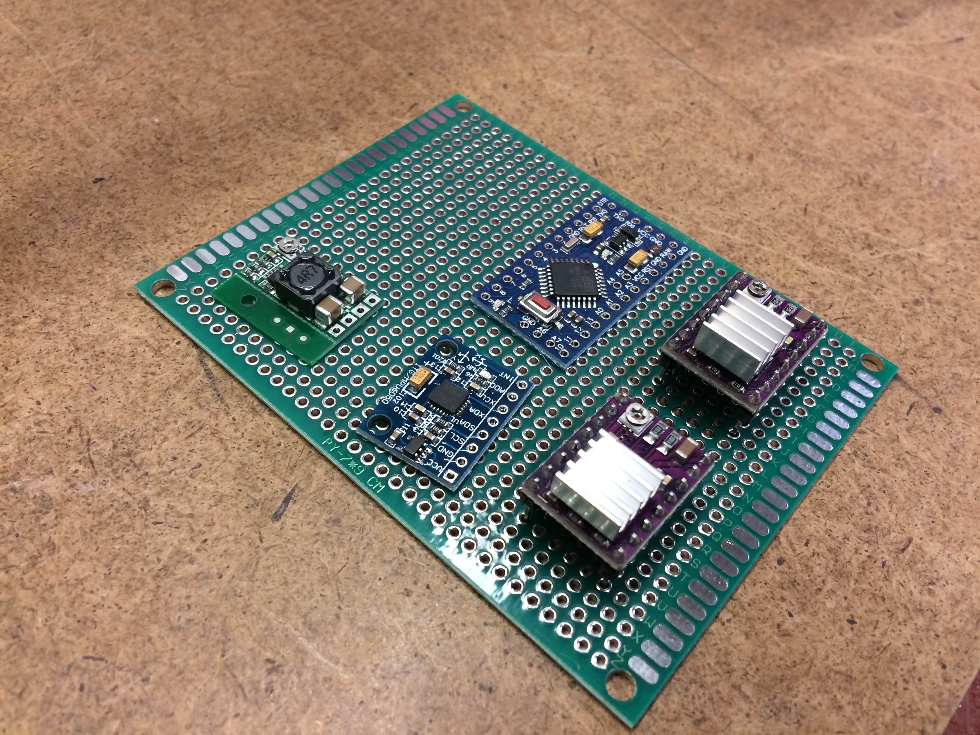
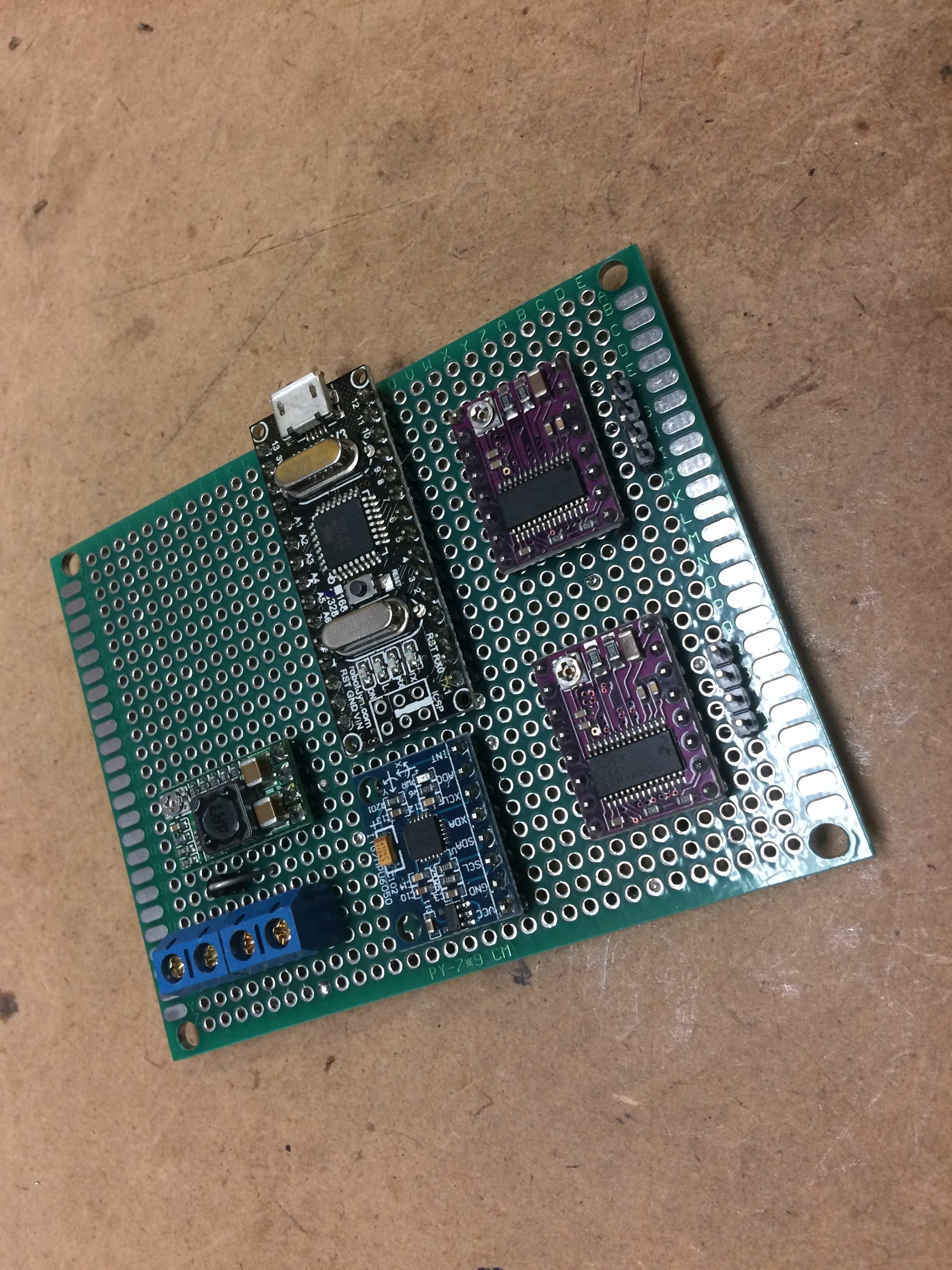
Normally I would use a NANO for something like this but the PRO-MINI is even smaller (cuz it doesn’t have the USB/Serial chip onboard) and since I had one I decide to go with it as the NANO was a bit too large. The caveat is that you need a USB/Serial adapter to program but the programming pins can stick straight from the board allowing and easier connection…
And the CH340 USB/Serial board are really cheap…
And I shouldn’t have to make many programming changes…
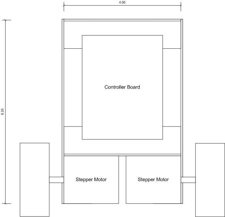
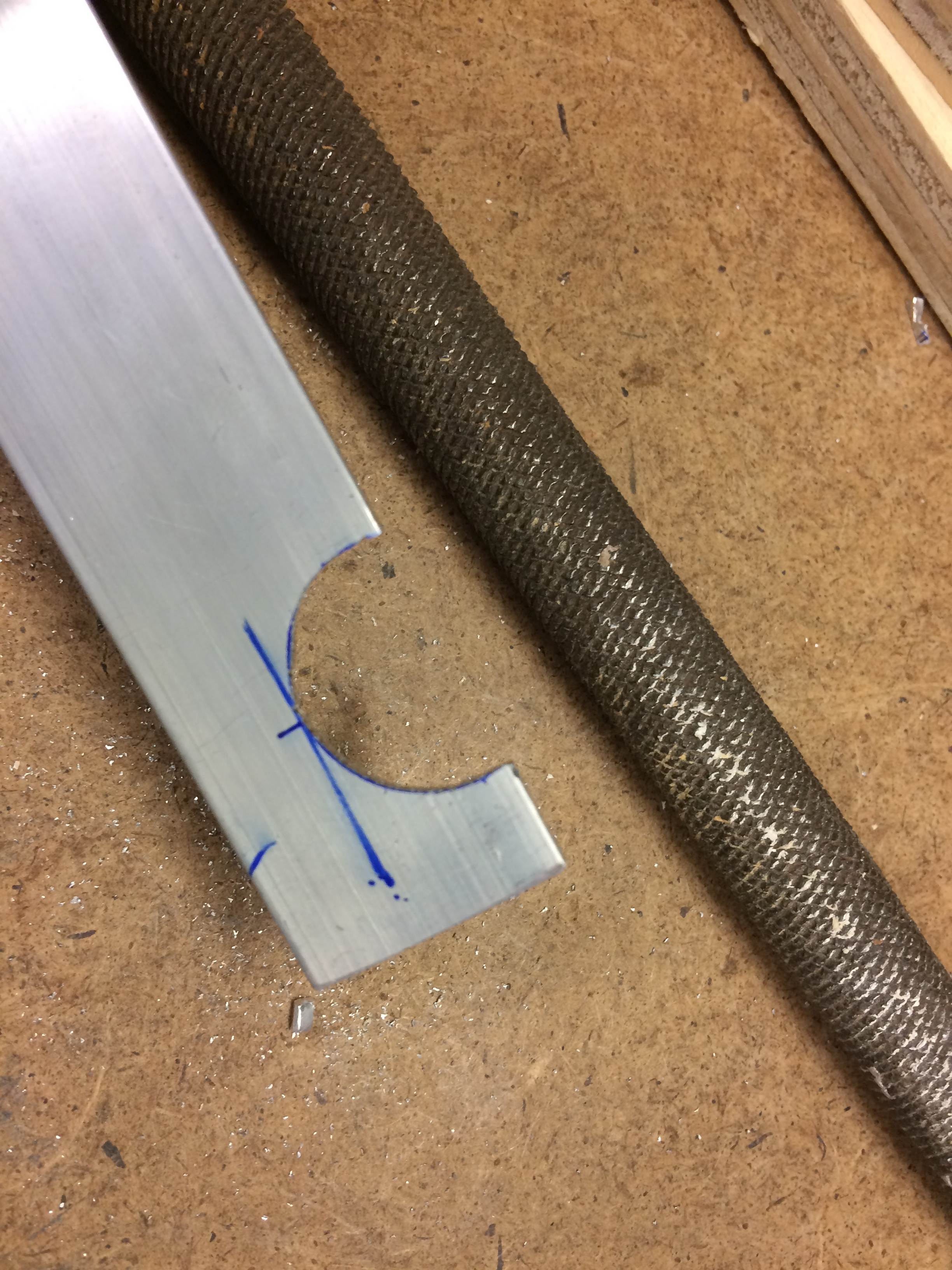
I decided to use a drawing program to figure out the best sizes for the aluminum. I figured better measure twice and cut once (though typically I do the complete opposite…
I’m going to use 1/16" x 1" angle. Tomorrow I will cut it to size and drill out the holes to mount the steppers. I’ll probably just pop rivet the pieces together to make the frame.
Next on to wiring up the circuit board… While normally I’d use sockets for the various modules I think I’ll solder them in place to keep a low profile (the sockets add 5/16" to the height)…
Trying to keep the motor power wiring seperate from the logic stuff…
I’m using some 22 gauge tinned bare solid wire for the main power connections…
Using heat shrink over some of it to prevent shorts…
Probably should get some red to be able to easily tell what is GND and whats is V+…
The terminal strip gives seperate connections for the battery and a power switch that I will mount on the frame…
I like this method of building prototypes. I have tried veroboard (strip board) but find this easier. You end up something approximating what a PCB would look like. This of course, assumes you spend time laying out everything and account for every part, which I never seem to pull off).
I tend to follow these steps:
Lay out parts in pleasing manner to fit board space.
Tack solder parts in place.
Run ground and power lines. I tend to use #22 solid wire for this. I use heat shrink tubing to protect from shorts as required.
Test all connections. Important to do this as you progress as fixing issues once you have a mess of wiring done is very difficult.
Run data and signal lines. I use #28 (or mebbe it’s #30) insulated wire wrap wire for this.
Again test as much as you can in stages to avoid having to access connection buried under later work.
Ideally you should use black and red heat shrink tube to denote GND and V+
Ideally you should use different colors of wire wrap wire for the signal runs.
I use what I have…
There used to be a “wiring pencil” product by VERO that used a similar wire (perhaps even thinner) that you would wrap around a pin and then solder as needed. The wire was insulated but would burn off with the heat of the iron to allow soldering.