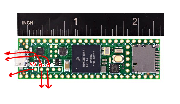
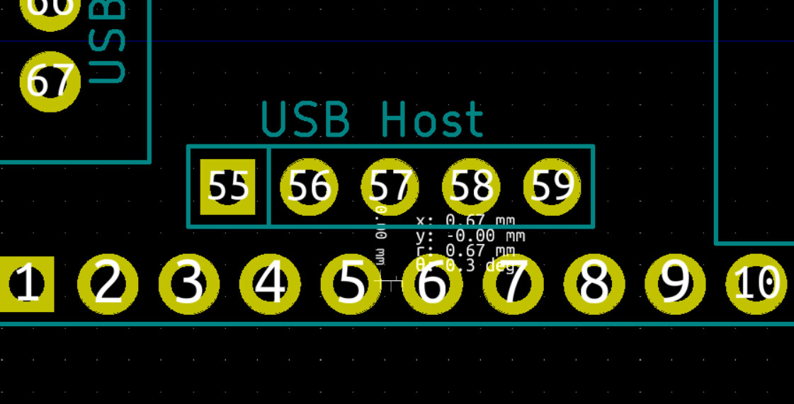
So I’m using the Teensy 4.1 for my synth/midi controller project now which has USB Host pins on board. Rather than accessing these pins by way of this special USB cable, I’d like to just have a proper USB port on my PCB. However, the pins for the USB Host on the Teensy 4.1 are tucked into the middle of the board, so before I create the wide traces at the proper impedance for the differential pair, I’m going to have to run some tiny traces past other pins that are very close to each other.
I’ve attached some photos for reference here below. The traces will probably need to be around 0.2mm wide and they will pass beside pins which will be also be 0.2mm from the trace. The pins the D+/D- pair will be passing by are carrying audio data signals. Will this cause interference on my incoming signal? Or is this ample space? I’m just running USB MIDI into the USB Host pins, so we’re still at USB 2.0 speeds, nothing major. The only other option would be just running some wires from the Teensy onto my PCB, bypassing the need to create narrow traces, but ideally I’d like to avoid that.
Any advice would be greatly appreciated, thanks in advance!
And maybe notnthe right solution for this job, but you can get surface mount 0.1" headers which free up the backside of the board for activities. https://www.digikey.ca/short/50wh8jwv
Assuming you are designing for 2-layers, 4-layer boards are getting mighty cheap these days, if you care about spec compliance for a USB project you’re probably going to need it anyway, the board area required to do the diff pair properly on a 2-layer 1.6mm PCB is absurd. For hobby projects I’m more or less only doing 4-layer these days, at small quantity the cost is basically the same (ie. disappears into shipping costs) and it makes life nicer.
It looks like there would already be quite a lot of room for routing signals to the ‘west’, though, probably enough if you don’t need to route anything else this way. If you’re really having a rough time you can also avoid using the 5V from the USB host connector specifically and just pull it from your 5V bus and either omit the current limiting or implement it yourself with a polyfuse or whatever.
Anyway it’s unlikely to matter. The impedance discontinuity where that cable breaks out to the 0.1" connector is probably worse than you would introduce by using the wrong track width for a few mm. Using your own fly wires would be much worse; how do you intend to control the impedance of that? In my experience USB Full/High speed is pretty tolerant to being mistreated, I’ve done some pretty nasty fly wire stuff, and definitely laid out boards with imperfect tracks, and it’s always just worked.
Oh that’s good to know that 4 layer boards are getting cheap, I was sticking to 2 layer because of assumed cost savings, but I do also have loads of space for the ridiculously wide trace lengths on my PCB.
Okay cool, that’s really good to know. I’ll just go ahead with the awkward trace routing past the Teensy pins and then the comically wide differential pair traces. If I run into an issue I’ll troubleshoot more at that point, but from what I’m hearing it will likely be fine.