Yup my partner got me this wonderful phone. What I wanted to do was find an easy way to try and use it on some modern devices aka a Microphone.
This process is relatively simple, most tutorials that I’ve found however are just wiring the speaker to and XLR cable and then Bob’s your uncle.
However I’d rather follow this tutorial which isn’t too much more work. You can get the mic and speaker working like normal with some simple re wiring. https://youtu.be/ppr3ilJP-I8
Here is the catch that may make this project a little impossible, I’d like to not cut the wires on this phone since it is a collector’s item. Here’s what I’m looking at inside, too. Pretty short wires.
What I wanted to ask, is would it be secure enough that if I were remove the PCB in here and find the contact points, could I use some conductive tape to tape down the wiring that I would do from the video here with a long enough 3.5MM 4 pole trrs cable, as I’d like to use like in the tutorial, rather than just wiring up the speaker to be a mic, which would work from what I’ve seen with an XLR cable as well.
Hey GraphicJon - first I must say this phone is completely awesome!!! Are you talking about taping down connections as an alternative to soldering? Someone else here might have some idea of how that would work but I think you would still get spotty connections and maybe a shorting hazard. Have you thought about hacking a bluetooth or digital audio headset to get the same functionality while removing the original innards of the phone (i.e. pretty much everything including the speaker) for safe keeping? That way you’d preserve it entirely but still get the functionality you’re looking for by using the hacked headset/headphone parts.
How important is the audio quality? If it’s a collector’s item, I would be hesitant to modify anything inside. What are your thoughts of interfacing with the phone through its already connected phone jack?
I’d be super interested in that avenue! I’m not expecting quality sound from it, that would be the charm, to use it for the bad quality for some recordings. My research down that path didn’t end well. There are some R9 adapters but phone headsets have a slightly different plug than this one. It may be an r11 or r12, would the idea be to rewire some plugs and convert it to work. This was the closest DIY I could find, but at best the author talks about improvements that are a little more advanced for me. I’m not a big hacker by trade, but I can follow instructions well.
Hi Janet, that would probably be a good alternative. I could store the guts somewhere and possibly install some parts, and it would sound better to, I’d imagine. I’ll look into this when I have time to remove the innards, as I’m unsure what it looks like in there. Bluetooth may take over some of my audio though, it would be nice if it just functioned like headset or just a microphone, but I could look for those parts, too.
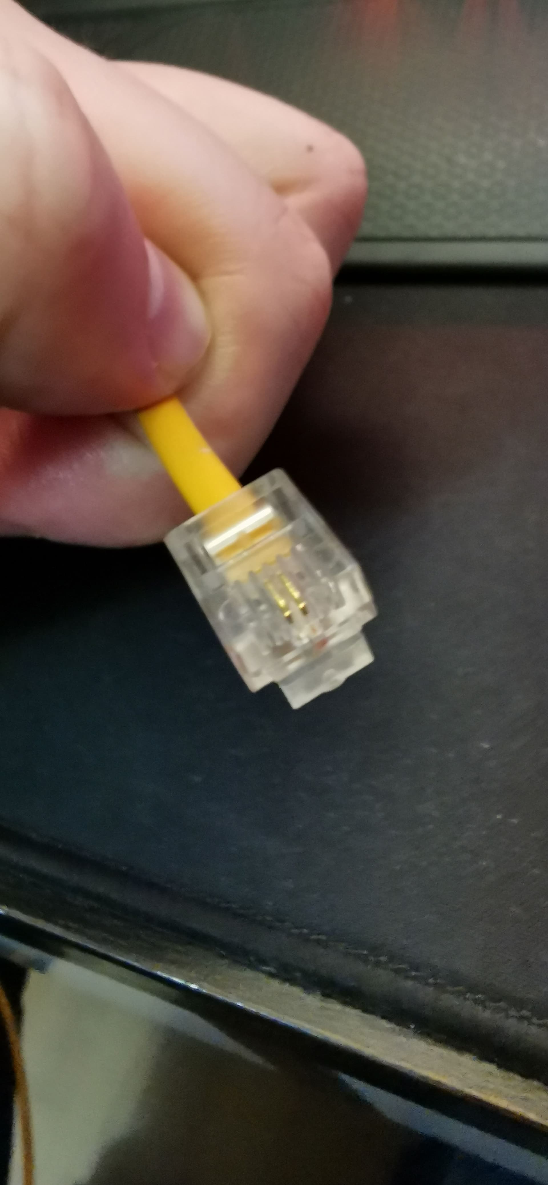
I think we can probably build something pretty easily. RJ11 is the standard for north America. Can you take a picture of the connector on it?
What are you trying to connect to ultimately? A phone? Mixing board? I ask because we’ll want to convert to the proper line level and drive the right impedance. Or we can even put a USB or Bluetooth interface in there.
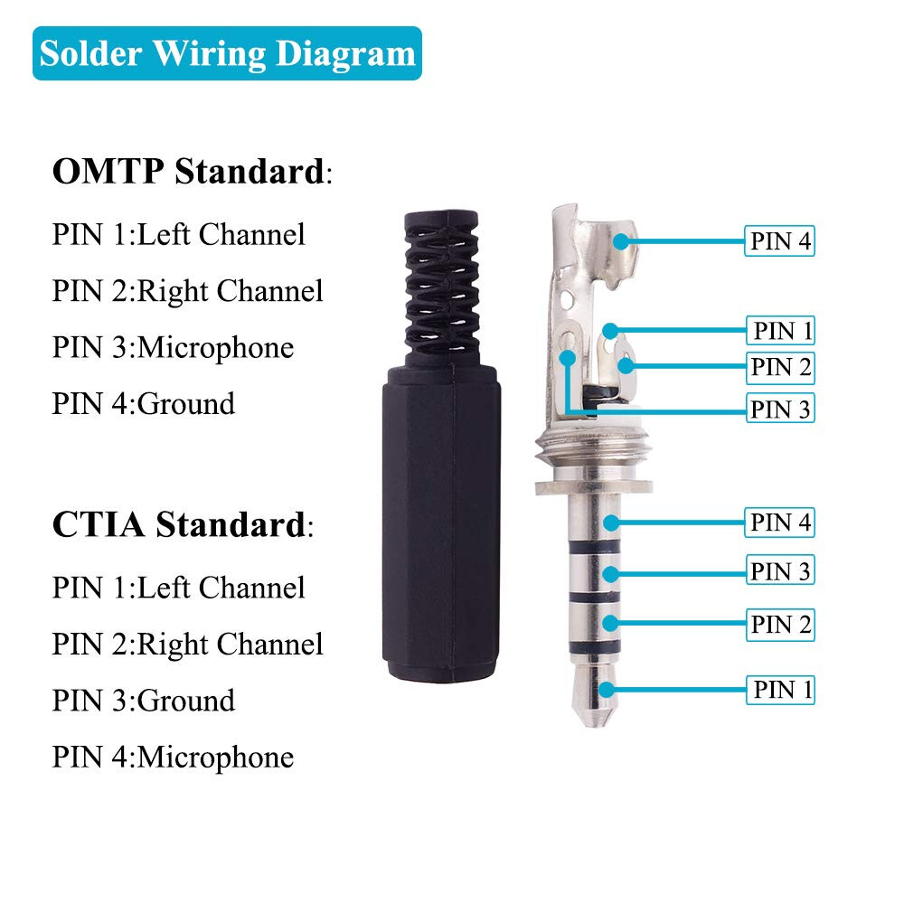
Originally I wanted to just use it as a microphone connected to an audio interface or to a device like the PC with a 3.5mm jack. the 3.5 jack seemed more ideal when I saw the video tutorial since the four wires on the TRRS type would have everything, and a 6.3 mm converter jack would work with a mixer, I think?
It does look like the jack has up to 6 pins, but only has two wires though, so I’m not sure what’s going on there. 9mm wide if that helps,
This way you can plug it into a computer , and use it like a handset for zoom meetings, or, using an adapter, plug it into a bigger sound system. We’ll shoot for impedance and levels of a standard microphone you’d plug into a computer.
I’ll see what I can find for doing this. There’s LOTS of history of doing this kinda thing, but it’s hard to find because it’s so old tech it isn’t super on the internet
I’m not really clear on what you are trying to do, ergo my previous deleted post. However, if what you’d like to do is put your working Garfield telephone on display as a functional conversation piece but you’d like to fiddle with telephone audio have you thought about putting a splitter at the telephone, or at the wall jack, and putting another ‘cheap’ phone in parallel? Something like a VTech phone for $20 (or less) gives you plenty of outputs (speaker, microphone, call display) to play with. You could cannibalize something like this without damaging your collectors piece.
@ddq Why did ya delete that? That was a really good post. That device is pretty close to what I plan to build, except I want to re to inject audio as well.
@Pat Yes I think if I were to put some guts from a phone like this inside, I could then maybe find a way to get it to work, that may be too advanced for me, but I appreciate the links.
Thanks @Rob_MacKenzie ! There have been a lot of good suggestions, but I like the idea of building this box much like the suggested phone patch from @ddq . If you have some ideas, I’m all ears. I’m not sure when I’d have time to come down to the hack space to hash out a plan, but chatting here about a plan works for me too. I’ll see what parts I can find locally. Just bear in mind I’m not really a hacker per say, but I’ve done enough wiring to repair one arcade stick and build another, so I think that I can handle this project. I just don’t know enough about electronics to design anything myself.
Feel free to message me here or @davem99 on slack if you need help with your electronics design or just want a sanity check of your schematics.
I don’t really have the time to design something (too many unfinished projects of my own!) but happy to review after you’ve had a crack at it, if you want.
Just updating that we came to a stall with the first design, I haven’t made any progress on this project. I’m still open to design ideas, though. I’ll try to reach out.
Sorry I haven’t got around to posting earlier. I didn’t have this when you made the original post but I later worked on a similar project.
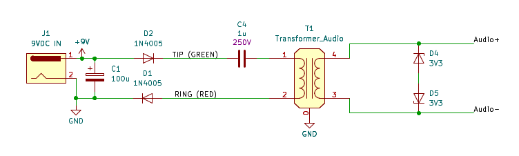
This design will allow you to use the handset as a microphone without modifying it at all. You could easily put this in a small box with an RJ11 input and a 3.5mm (or whatever) audio output jack. You may need some additional amplification / input gain depending on what level you get from the phone. I’d try it without an amplifier first.
Phone handsets are supplied with DC power via the phone lines, so that’s what the 9VDC input is simulating here.
C4 blocks DC current from the transformer windings. I dropped a couple of these transformers in the transformer bin at the space last summer, and I doubt anyone has used them yet. If those are gone what you want is a 1:1 / 600 ohm to 600 ohm audio transformer. These are the ones I bought: TRANSFORMER, AUDIO, 600:600 OHM, 60-606-0
A standard 9V battery is probably sufficient here if a continuous 9VDC supply is not available or practical.
Connect the two wires of the RJ11 cord to the nets labelled TIP and RING.
Zener diodes D4 and D5 clip the output to +/- 3.3V to reduce the chance of blowing up your audio input if you get a big spike for whatever reason. You can use a lower voltage Zener for extra safety (or if you want to intentionally introduce extra clipping/distortion).
With a few modifications, you could also use this to talk directly between two phone handsets. Obviously there would be no dial tone or any kind of dialing, just a direct connection.
(Information provided as is, no warranties, no refunds. Check it on a thrift store/junk phone first so you don’t asplode Garfield’s head.)