Turning my clunky old beginner keyboard into a fancy MIDI controller

I’ve been posting about this on slack but figured it’d be better to create a topic here to use as a sort of project log that more people can see. Hopefully some folks find this interesting! I’ll be tearing down an electric piano, figuring out how the keys work, and building the best MIDI controller I can with the parts and a bunch of new stuff.

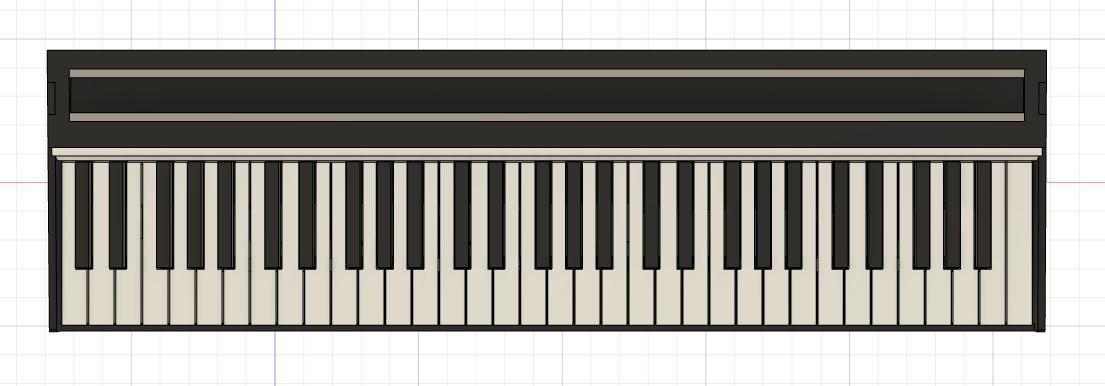
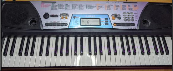
My family got this Yamaha PSR-170 in 2002 or something. It’s a beginner keyboard with a bunch of built-in samples (including some entertaining ones like a very enthusiastic guy yelling stuff like “DJ!”, “Oh yeah!” and “Dictionary!”). I never used it much myself but years later it ended up in my closet and sat there for a while. I started learning piano last year and it’s been pretty handy for that, but it has no velocity detection, no USB midi, and it’s absolutely massive. But the keys themselves are still decent and it’s nice to have 61 of them. And for various reasons this has ended up being a somewhat sentimental item, so I felt it deserved a new life rather than being replaced and most likely discarded.

image

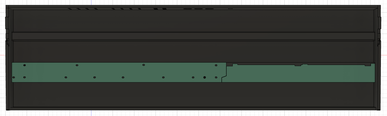
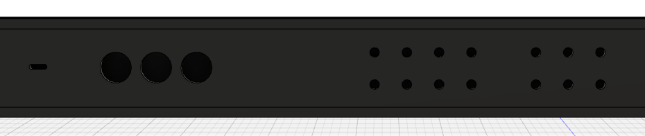
So, here’s the guts. It’s got a bunch of stuff in the top including some speakers, amplifiers for said speakers, I/O, some ROM to presumably store all the built-in samples and wave tables, and a YMW728-F “tone generator” to do the actual synthesis. The information I can find online about the chip is sparse and it sounds like kind of a nightmare and isn’t worth salvaging for anything cool, but that’s not super surprising considering the tier of this device.

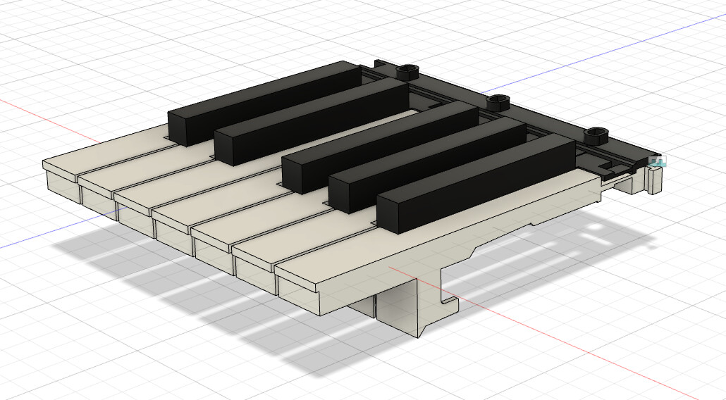
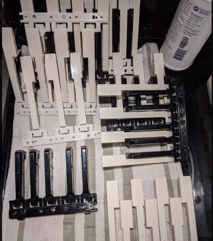
I cleaned the keys, which come apart easily once unscrewed and are split into separate assemblies for each octave, each with 3 parts.

image

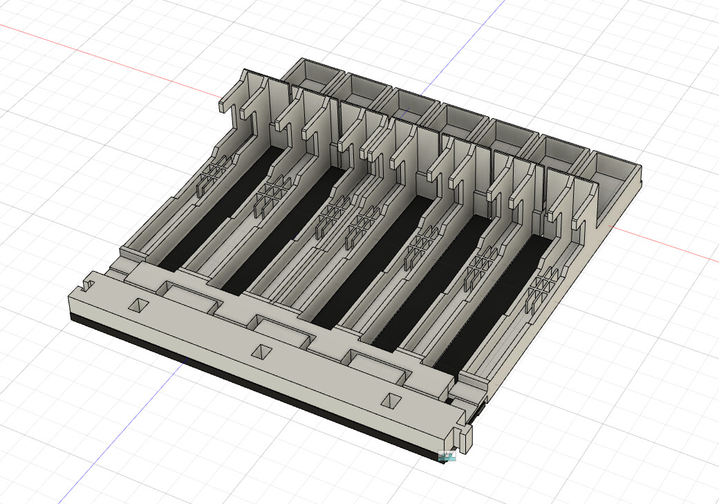
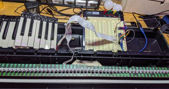
With the top set aside, I was left with just the key matrix board, ribbon cable, and keybed, which will serve as the base for my new MIDI controller. I connected the ribbon cable to an arduino nano and set about figuring out the key matrix.

image

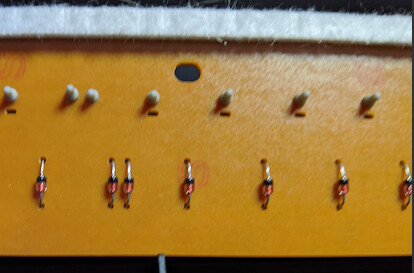
It’s a circuit with a bunch of pins (in this case 17) arranged as rows and columns, with each cell representing a single key with a switch connecting the row and column pins. By setting a given row and column pair to LOW and INPUT_PULLUP respectively, the arduino can detect that a key has been pressed when the input reads LOW, indicating that the key press has closed the switch via the conductive pad on the bottom of the rubber dome. Diodes are added to prevent “ghost key presses” from keys interfering with each other. Thanks to this type of circuit you don’t need a wire for every key, which would be a complete nightmare. This is also commonly used in computer keyboards.

image image

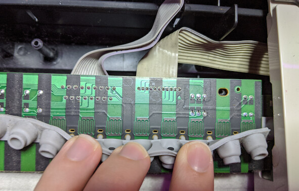
After a bit of poking around with a multimeter, I was able to figure out the row and column arrangement for the key matrix (11 rows x 6 columns, with the first 5 cells of the first row empty):

image

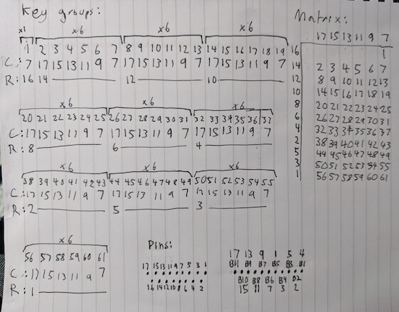
Following a bit of cursing while I tried to figure out why some keys were behaving strangely (pin A6 and A7 on the nano are analog only, so digitalRead always returns 0), I got everything working. Then I swapped out my arduino for a teensy so I could have a proper USB MIDI device and not have to explain to my piano teacher why my piano was in pieces for my next lesson. After adding some delays here and there due to the teensy being so fast the voltage at the input pins couldn’t change quickly enough, it all works perfectly!

image

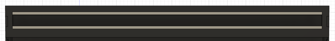
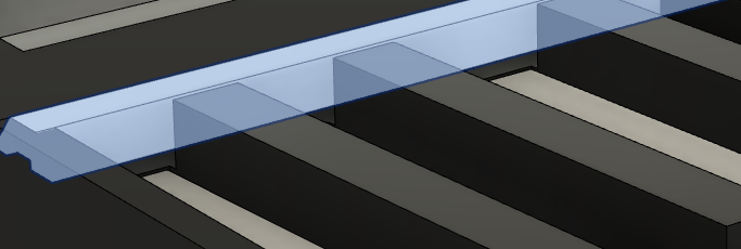
After that I moved on to designing the case, which I’m still in the process of doing. I’ll post some more updates soon! I’m really happy with how this is going so far.

9 Likes

Here’s what I’ve got for the case so far, along with some details on the features I’m hoping to add. It’s a bit ambitious for my skill level but why ever try to make anything easy, right? I’ll probably have to compromise and simplify some stuff but I like to aim high. This was a great way to improve my fusion 360 skills at least. The case will be mostly 1/4" birch plywood. It’s much, much smaller than the original and will fit under my monitors behind my keyboard and mouse, which is ideal.

I spent a couple free evenings with a set of calipers and some uh… enhanced gummies… and measured out the keys in gratuitous detail so I can get the mounting placement in the case and the travel distance for the switches/velocity sensors right. I probably didn’t need to go as far as I did but it was fun and, again, a good way to improve my CAD skills. The bottoms of the black keys are the same shape and only 2mm behind the white ones so I decided that was easy enough to figure out without going through all the same effort with them. The most important details beyond that were the screw locations and the depth of the assembly itself.

With the keys done, I made a quick outline of the key matrix pcb and mounting holes, then added mounts for everything inside the case. I still need to add the mounting holes for the keys and the right side of the pcb, as well as the velocity sensors. For those my current plan is:

  • order some of this and some thin strips of foam to place underneath
  • write some test code and try out various heights and placements with one key for the best feel and response
  • place the foam strips and segments of velostat for each key
  • wire everything up in a similar arrangement to the key matrix (potentially re-using some of the pins)
  • write the code to read every sensor and calibrate each key if necessary, though I’m hoping any differences will be trivial if I get the layout right

I got bored of measuring stuff and had a bit of fun adding some potential features to the case. I know I wanted a bunch of controls along the top, but I’m not sure exactly what, and I’m sure my needs will change as time goes on. So naturally the solution is to make it modular. I already want to use this with my eurorack, so I decided to just make the top a eurorack-compatible 160HP 1U row (specifically pulplogic format). I’ve already made a handful of 1U modules for my own modular and it should be easy enough to make some that are just dedicated sets of controls that connect to a header in the case for MIDI support. This seems like overkill but I think it will work really well with the other features I have planned for this case. It will also be simple enough to swap out the top panel for a different layout if I change my mind later.

The other main features are the rear I/O. I’ve just added some vaguely placed outlines for holes right now until I actually put together a PCB with the final layout, but it will include:

  • USB-C for power, MIDI, and audio
  • (possibly) A supplementary power input for the modules
  • MIDI DIN ports for in, out, and thru
  • DC-coupled audio interface for audio or CV communication between DAWs/VCV rack and physical eurorack modules. The current plan is for 6 inputs and 8 outputs using this codec which is known to work well with the teensy audio library.

And lastly as a bonus that most likely won’t make it into the first version of the top panel, an LED strip and acrylic diffuser along the top of the keys for programmable blinky. Because come on, I had to.

image

This is what it looks like from the side. Still not 100% sure how it’s going to work in the end (I need to make sure I design parts I can actually make) but there should be just enough space between the back of the keys and the top of the case to fit a 60 LED/m strip of SK6812s with a thin channel (using worst-case measurements in this screenshot). The spacing between the keys is conveniently almost exactly that of the LED spacing on such strips, so with a short gap between each octave it should be almost perfect and unnoticeable with the diffuser.

I haven’t included many pictures of joints between the pieces because I’m still figuring out what the best way to do that would be, depending on the method I use to cut them. But I’m hoping to use finger joints and wood glue for everything but the top, which I want to be removable. For that I’ll probably just add some sort of clip if it comes loose too easily.

This post ended up longer than expected but it’s now more or less completely up to date with the current state of things!

6 Likes

wow!

This topic was automatically closed 365 days after the last reply. New replies are no longer allowed.