What I’ve noticed is that one sensor by itself works fine, but I get inconsistent voltage levels when both sensors are connected to the Arduino.
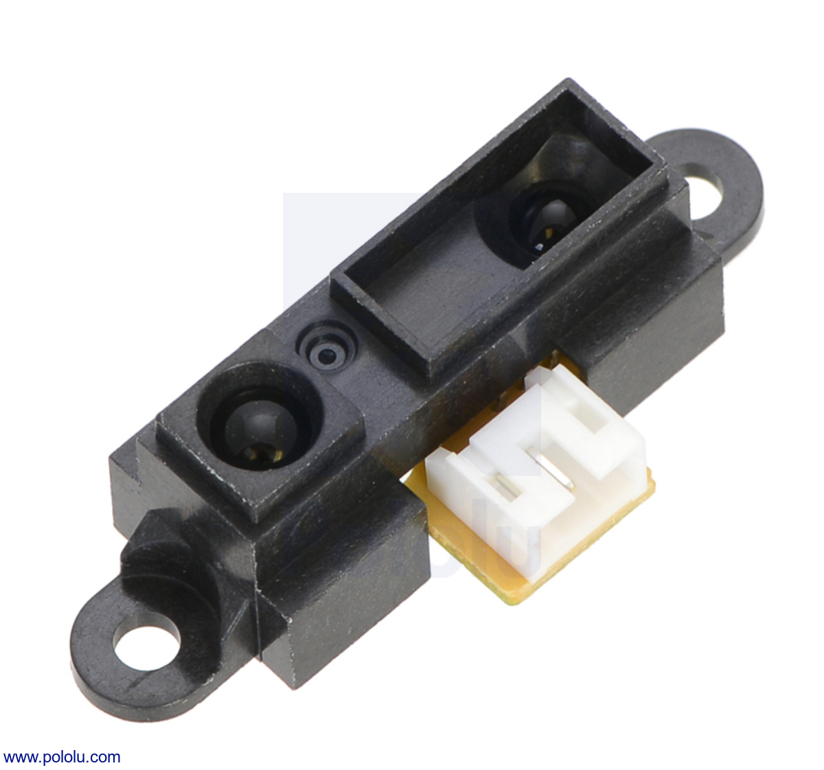
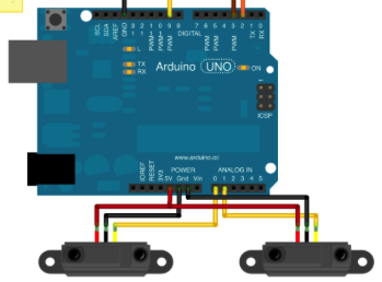
The sensors have 3 leads: power (5V), ground, and the sensor output. I connected the power leads in common to the 5V, the grounds in common to the same ground, and the sensor outputs to their own analog input, like so:
I’m powering the Arduino via the USB port on my laptop, and using analogRead to get the voltage level from each sensor. I’ve controlled for cross interference by keeping the sensors facing away from each other. When I write a simple sketch to dump the raw values to the serial monitor, I see one sensor working correctly, and the other sensor either staying at a higher, fixed voltage or wandering in semi-sync with the other functioning sensor.
Did you follow Pololu’s advice to place a 10uF decoupling capacitor near the sensor? If not you may be suffering ground bounce and/or supply instability, especially since (I think?) Arduino analogRead uses Vcc as reference voltage.
I expect this is due to the design of the analog pins on the AVR microcontroller - the pins (“channels”) are multiplexed to a single ADC. The ADC needs a bit of time to sample (charge its internal capacitor through a resistor) once a pin/channel has been selected.
Due to the design of the Arduino libraries there isn’t a super-elegant way to do this, other than issue multiple analogRead()'s for each pin/channel with delays in between.
Something like this:
analogRead(sensor1pin); // dummy read; sets the channel
delay(10); // give the ADC time to sample
sensor1res = analogRead(sensor1pin);
analogRead(sensor2pin); // dummy read; sets the channel
delay(10); // give the ADC time to sample
sensor2res = analogRead(sensor2pin);
Often, digital sensors will work better with an added (external) pull up resistor (or pull down, in some cases) Internal pull up resistors may be minimal or non existent, so adding your own often helps. This lowers the impedance of the signal line, soaking up noise in the process. 2.2K is usually a good bet. As for delays between analog reads, great idea, but even better to have your Arduino do useful tasks between reads, like sending data or turning on some LED’s.