The Taig is going to get new stronger closed loop stepper motors and better controller box. I am going to post all the details, data sheets, CAD models here for people who are interested, want to contribute, or want to build their own controller.
9 Likes
https://drive.google.com/drive/folders/0B2qFQsJCZJBAV2ozMnpJSEFFV0E?usp=sharing
Here is the link to the folder of files I will share.
1 Like
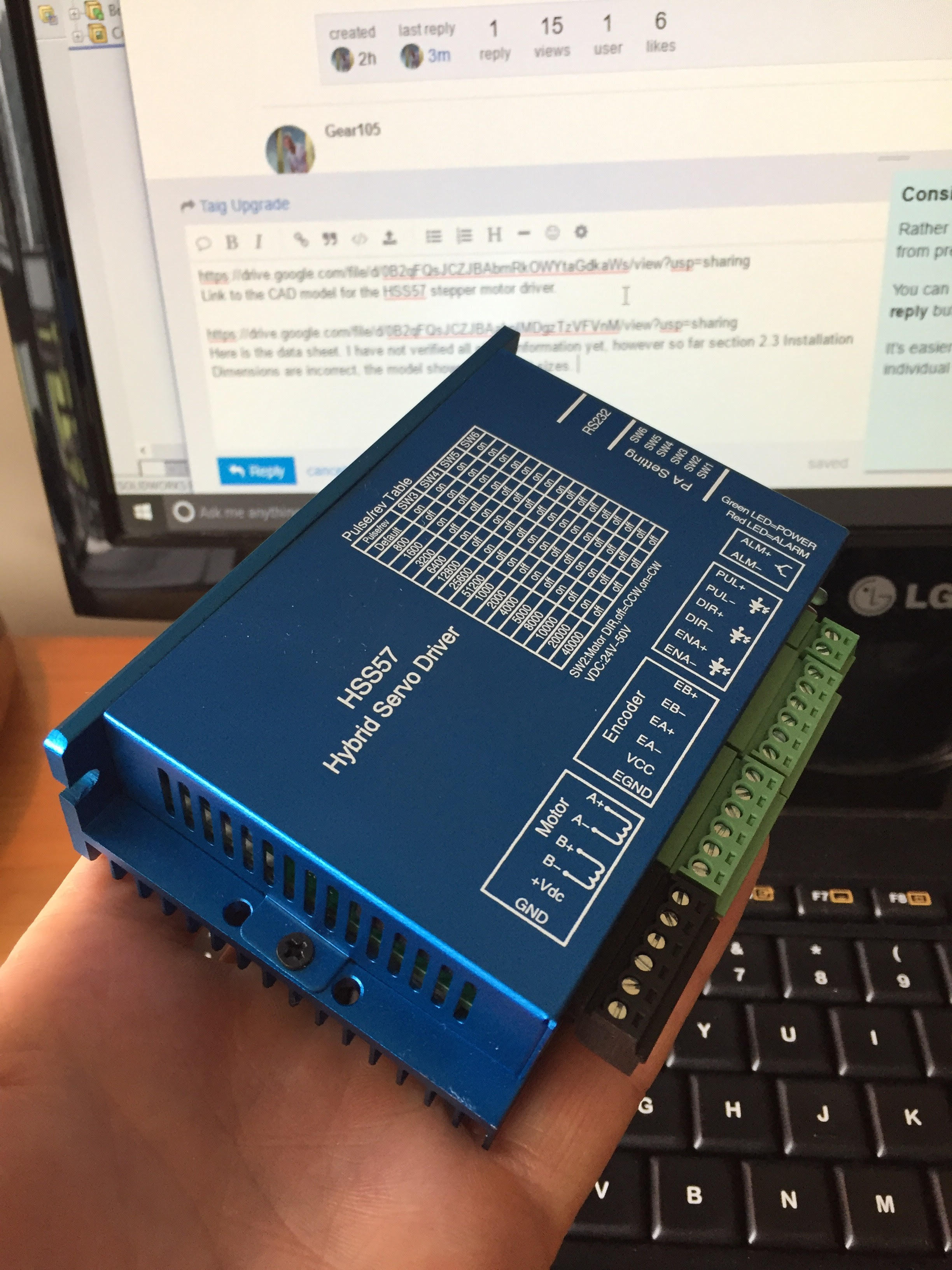
https://drive.google.com/file/d/0B2qFQsJCZJBAbmRkOWYtaGdkaWs/view?usp=sharing
Link to the CAD model for the HSS57 stepper motor driver.
https://drive.google.com/file/d/0B2qFQsJCZJBAakpIMDgzTzVFVnM/view?usp=sharing
Here is the data sheet. I have not verified all of the information yet, however so far section 2.3 Installation Dimensions are incorrect, the model shows the correct sizes.
4 Likes
Awesome!
I’ve crosslinked this thread from the Taig’s wiki page.
Looks good. Is there any constraints on the encoder resolution, i.e. does it have to be
the same as the motor steps/rev?
@Rob There are no constraints on encoder resolution. The encoder included on these motors is 1000/r. The motors will micro step much more finely than that even, however they will struggle to hold their positional accuracy at finer micro steps. The encoders are intended to provide a reliable feedback loop to the controller to be able to sense errors. There is an alarm circuit on the driver that gets triggered when a maximum amount of error is determined like in a crash. I believe the encoder will help these motors also be more accurate between steps up to the resolution of 1000/r.
In other controller news, this http://www.hindtechnology.com/ is a nice option.
I ordered, https://cnc4pc.com/motion-control/breakout-boards/c10-bi-directional-parallel-port-interface-card.html this as a breakout board and this https://cnc4pc.com/motion-control/charge-pumps/c4-safety-charge-pump.html a safety charge pump to disable the controller while the PC is booting up, instead of unplugging the controller.
I am waiting on the delivery of the power supplies before finalizing their CAD model to the data sheet.
I’ve been looking at wire ducting, DIN rails, and terminals for inside the controller box to keep everything tidy.
I would really love to put the PC right inside of the controller box and drill and tap and ATX motherboard layout and mounting points for the power supply ect… but that may be a bit out of scope and over complicating things.
1 Like
Does the mill currently have limit switches?
I’m planning on picking up some inductive ones and I’d be happy to pick up a few more if you’d like along with other misc parts you may need. Thinking of ordering some bellows/way covers for the Y and or Z axis too.
Really like what this guy has done:

That would be pretty nice to add some limit switches. Do you have any data sheets yet?
Planning on getting these ones:
They’re 2 wire normally open so should wire up the same way as the clicky microswitches.
This topic was automatically closed 365 days after the last reply. New replies are no longer allowed.