Last night I grabbed a bunch of the supercap modules as I want to make some solar powered nightlight throweys for gifts and to have around. The plan is to make solar powered luminescent mushrooms that respond to local vibration (accelerometer based).
To start that off I went and took a close look at the supercap modules and think I’ve more-or-less figured them out.
First and foremost, the two I tested work fine and all of the four I checked the capacitors on had working caps. These seem to be functional units with just some thermal issues while charging.
What they are:
- 20F 2.7V Capacitor
- 1.2A constant current source with 2.2V cutoff
- 5V input (possible current sense input, didn’t test)
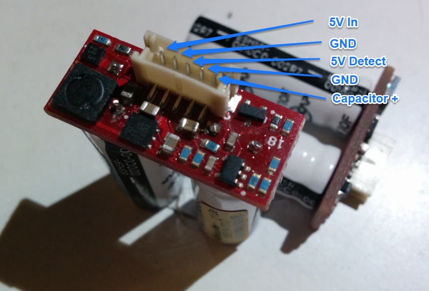
The constant-current/constant-voltage power supply needs 5V to operate as lower than that the capacitors aren’t charged fully. It also tends to heat up pretty bad if you try charging off, say, 3.3V.
The main component that heats up is the little SOT23-5. It looks like this is a supervisor of some sort and it’s connected to the detect pin. Without the detect pin powered, the switchmode will not turn on.
Once the capacitors are fully charged, the board draws 100mA continously, I’m not entirely sure why. If you don’t power up the supervisor/supply the board takes about 9mA leakage through the components and capacitors once the caps are full.
You can use these modules without using the onboard charge circuit, you just have to follow the spec sheets for the capacitors:
https://www.digikey.ca/product-detail/en/nesscap-co-ltd/ESHSR-0010C0-002R7/589-1002-ND/946802
So keep charge current preferably under 8A (4A each) and maximum voltage at 2.3V (2.7 if you’re feeling lucky)
From Digikey these capacitors are, well, we got one hell of a donation with these things:
https://www.digikey.ca/product-detail/en/nesscap-co-ltd/ESHSR-0010C0-002R7/589-1002-ND/946802