Hi all,
A friend of mine is looking to build a monitoring system for a sump pump. Can you folks give suggestions?
Here is his idea:
So I need some hardware hacking advice, and I was hoping you could help. I think I can figure out what I need about Arduino software, and further up the stack, but I really don’t have the first clue about basic electronics hardware, other than basic polarity, voltage, amperage, induction behaviour, half-forgotten-grade-11-physics kinda stuff.
The problem:
Last week, when I was driving on a long trip, I got a text from my house indicating that my sump pump (for storm water) had failed in some way - this means my house could flood within hours. I had to drive down to where there was decent cell reception and deploy a squad of troubleshooters to solve the problem. Even when I was down to where there was connectivity, I had no visibility into what the problem might be, I just had to send my plumbers over, who were not able to immediately diagnose the problem. The alarm eventually resolved itself, and when I get home tonight I’ll be able to troubleshoot it from there.
The context:
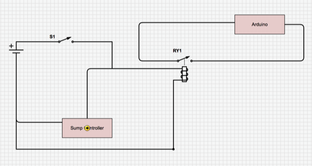
The sump pump controller unit controls 2 pumps (by switching 110v circuits to them on) and is informed by 3 floats (also 110v circuits, closed when the float is floating, open when it is hanging). The wires for these circuits are simple conductors running from the controller unit underground about 50 feet in a conduit to the 14-foot-deep sump in our front driveway.
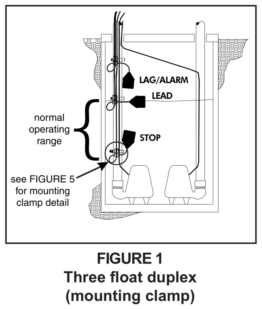
There are 3 floats, and they are, from bottom to top: a stop float, a start float, and an alarm float. When the water level rises high enough to float first the stop float, and then the start float, a pump is activated; the start float turns off as the water lowers, and the stop float eventually turns off as well, which turns off the pump that was running. The water rises again, until the stop float and the start float are both floating - at which point, the other pump runs, until the stop float stops floating - and the cycle continues, alternating pumps each time. If the start float does not float (fails, or gets tangled) or the pump that is being powered fails, then the water will float the stop, start, and finally the alarm float - when the alarm float activates, the controller turns on both pumps and sends the alarm to the ADT household alarm system, which has an ethernet bridge to a free monitoring site, which texts my phone and the phones of a few friends close by who can come fix things if I happen to be out of cell range or dead or something.
The plan:
- For each of these 5 conductors, I want to put a clamp-type induction sensor around the conductor, and plug it into an Arduino board.
- I’ll write a simple Arduino program to continuously poll the sensors, writing a stream of data to an SD card (using an SD shield), and sending the data up in chunks to cloud storage somewhere (using an Ethernet Shield).
- I’ll write a web app somewhere (probably with javascript, blech) to consume the stream of data and graph both pumps turning on and turning off, as well as the floats going up and down, over time. Plus hopefully a live-animation page that shows an actual visualization of the sump floats and pumps, reconstructing reality in a moving image (well, not completely… without an actual water-level sensor (different project) I can’t correctly show the water rising and falling in the sump pit). For extra credit, I may implement some stuff to tell when the pumps start drawing more or less amperage than they historically have, indicating that possibly they are heading for failure.
Hardware:
SJE-Rhombus dual pump controller panel: this is the installed unit that controls the pumps.
Arduino Uno board: I already have this, an OSEPP Uno R3 Plus, whatever that means.
Ethernet shield: I already have this, it appears to plug directly into the arduino board and pass the inputs through
SD shield: I don’t have this, I’ll probably pick up one of these: https://www.sparkfun.com/products/12761 and https://www.sparkfun.com/products/11417
Induction sensor: I’m thinking: https://www.sparkfun.com/products/11005. I’ll need 5 of them.
Prototype breadboard: https://www.sparkfun.com/products/7914 and https://www.sparkfun.com/products/12043Questions:
- Any suggested changes? I’m not married to any of this and I could easily be making poor choices.
- The induction sensor ends in a 3.5mm audio jack - I guess the thing to do is cut, strip, and plug into a breadboard, and then jumper that lead into an input on the arduino… possibly with a resistor along the way. Can I just take this wire (whatever gauge it is) and jam it into a breadboard rig? How would someone who knows how to do this, do this?
- I know the induction sensor should work on the 1hp pumps when they’re drawing amperage… but I wonder if I’ll get any significant response from the floats, considering the load there is probably minimal, just enough to judge connectivity. the pump load could in principle be running through the float circuits, but I know that in some cases the floats are on, but no amperage is being drawn, because no pump is running - for instance when the stop float is floating but before the start float is floating, no pump is running, but the float is up. So the circuit could be connected, but no significant amperage is going through - is there another, much lower-power induction sensor I might need in order to detect current in this case? I guess I’ll use a tester to figure out what comes out of the induction probe when it is clamped around the different wires.
- There’s an alternative to the induction sensors; I could wire the 120v conductors going into the sump pump controller to a set of dry contacts (an optical relay of some sort?). There are several downsides to this - on the pump circuits, I wouldn’t have the benefit of knowing how much power is being drawn; later on I hope to use this value vs historical values to determine when a pump may be going bad. Also, my insurance may be voided by messing directly with the wiring - a touchless solution is preferable.
Your thoughts?