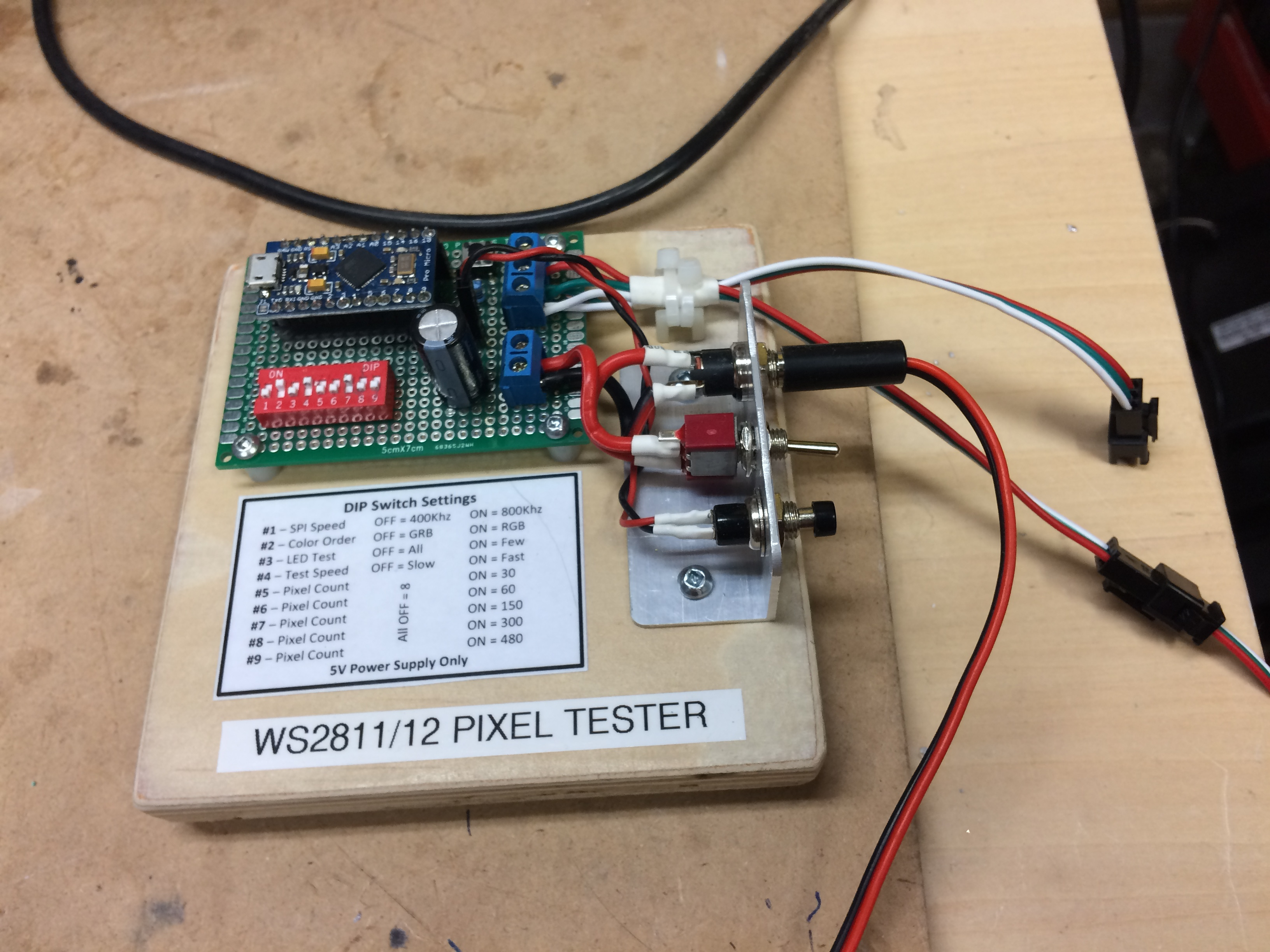
Now it’s time to wire up and install the controller. In the photo above I’m using a LED tester to generate the signals to make sure all the leds were working before I glued it up. I made this up a while ago for this purpose cuz I got tired of having to rig up an Arduino to test the LED strips. It’s an Arduino NANO clone running some NeoPixel test code. I added a DIP switch to allow various selections for the NeoPixel library options:
For the controller I had thought about using a PartyCat. I wanted to have a USB connection on the case to allow for firmware updates. I have some cheap USB/TTLSerial adapters coming from AliExpress but no idea when they will show up. So I’m going to go with a NodeMCU (v0.9) that I have kicking around. I am going to mount it on a large proto board to allow for the various required subsystems like the 5V to 3.3V power supply and the level convertor require for the Pixel strip. I also want to have room for future additions like a sound module and perhaps other lights and such (I did rig up that mirror ball a while back for a purpose).
I have to make up the strips to hold the tube in place. I will use 1" wide thin aluminum and will try to place a layer of thin white foam (like they use for packing sometimes) between the tube and the brackets/strip. I’ll also use clear silicone to secure each electrode (located at the ends) to the L brackets. Then finally I’ll run a bead of silicone along each side of the aluminum channel and the tube.
But first I have to build the ESP-8266 based controller board and get it installed cuz working on the insides will be quite difficult once the tube is mounted.
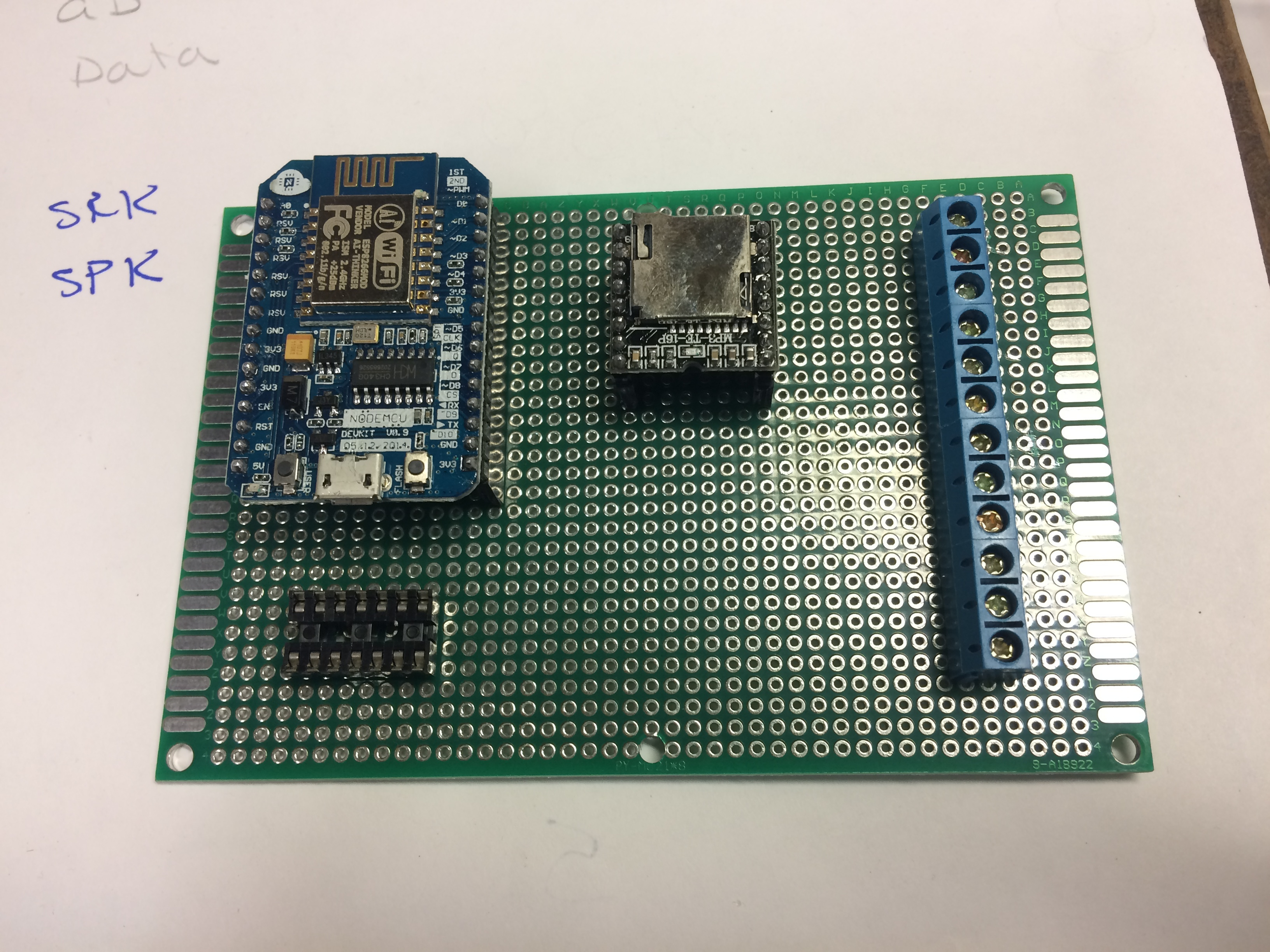
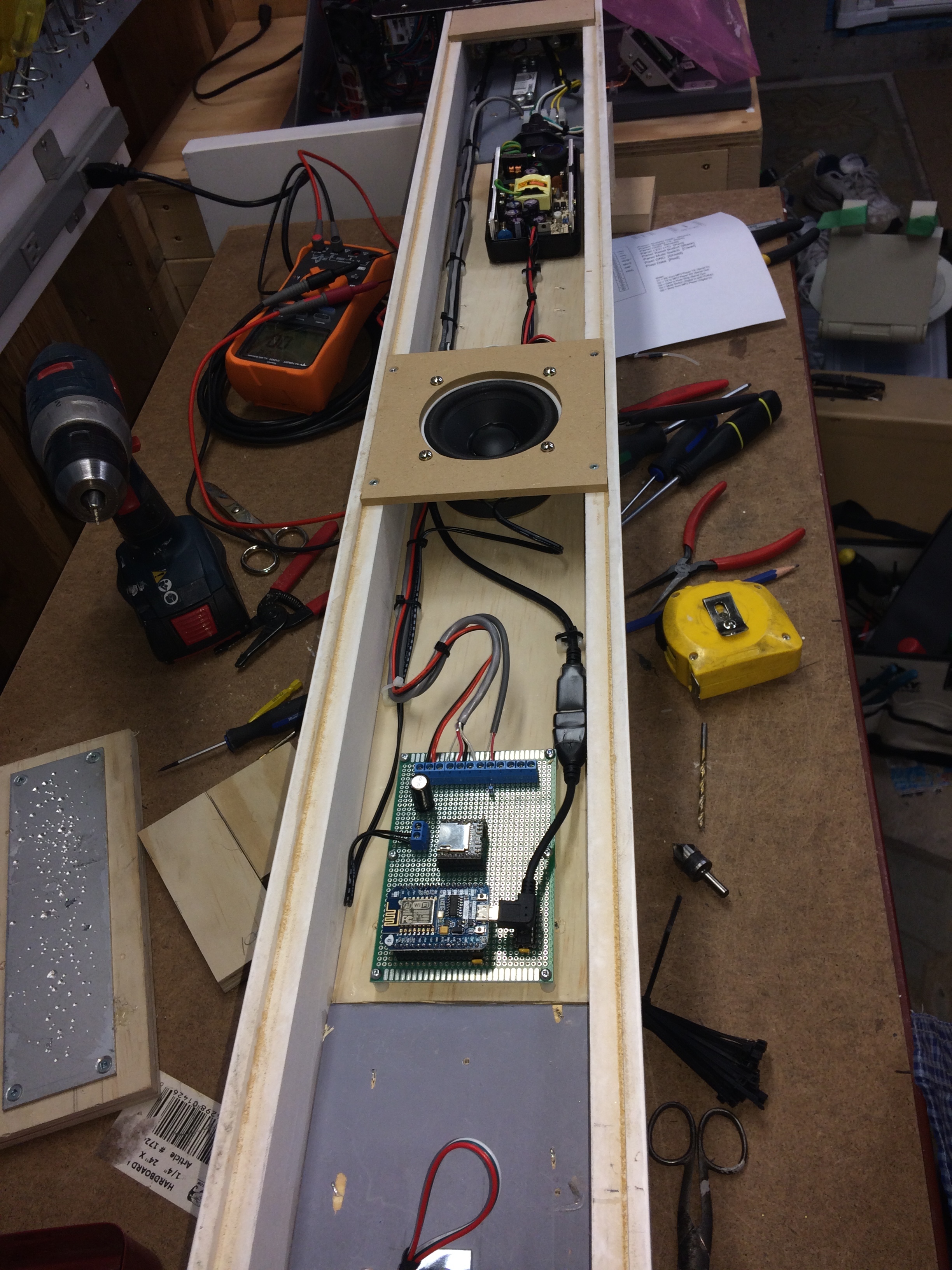
Decided on used the NodeMCU that I had. Found a right angle adapter cable (unfortunately the micro USB connector is upside down of what I needed, hence the USB cable coming across to the other side) . Here is the rough layout.
Now time to get wiring the board… Need to add a 3.3V regulator (will use a LD1117V33C) and a 3.3V to 5V level converter (will use a SN74AHCT125N), to start I just need the one pin for the WS2812s but hope to add more I/O in the future.
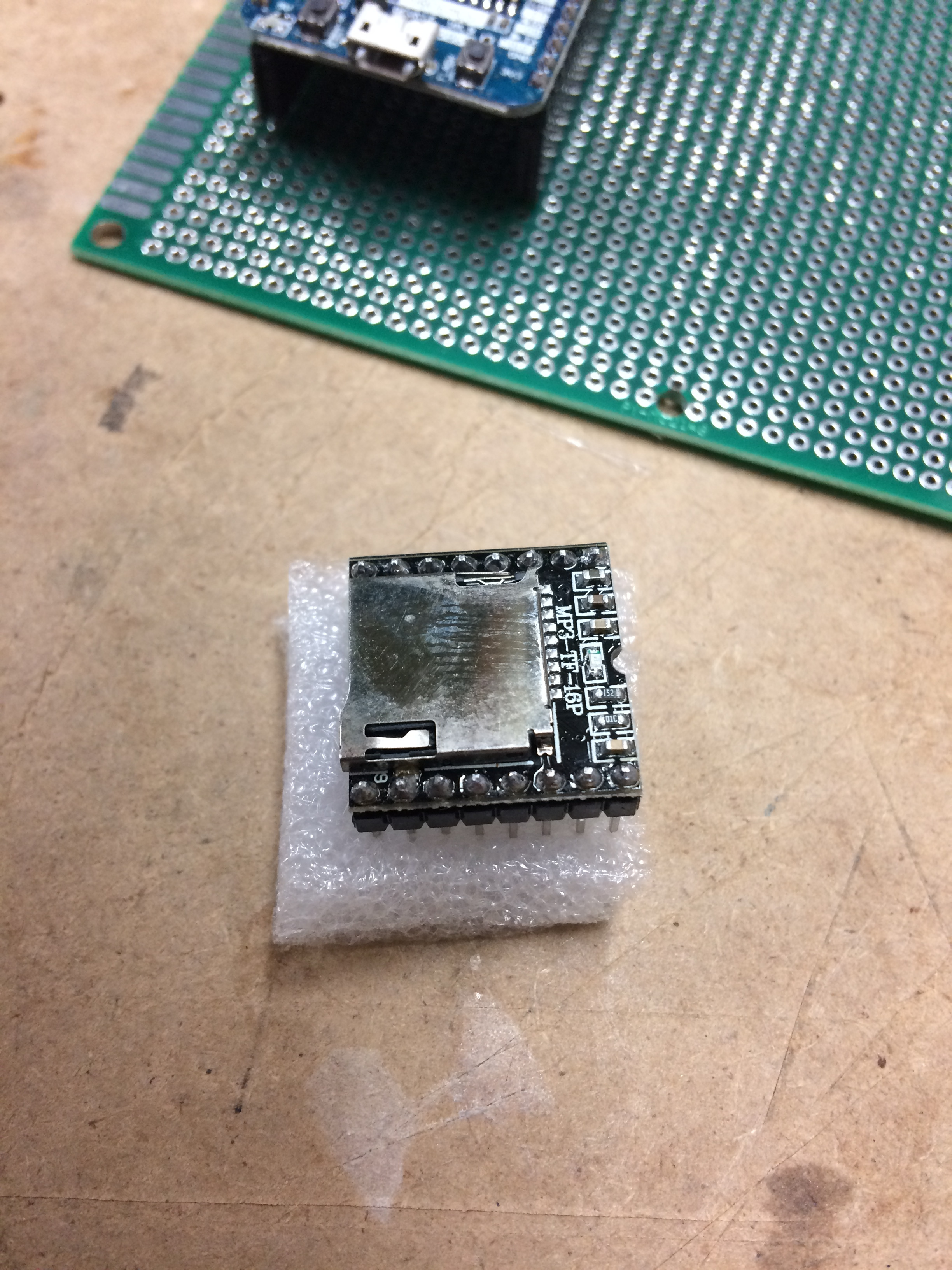
So I rigged up one of the sound modules and for what it cost I’m pretty impressed…
Loaded a few mp3 files (count of 1 to 10 and a few laser soundy things) and ran a sketch that plays the sounds one after another…
Control is via a serial link (need 2 pins and it’s low bandwidth so the SoftwareSerial library lets you use almost any of the Arduino pins) and uses 1 digital input to monitor status (so you don’t start a new sound till the current playing one has ended)…
Here is the code I used:
Here it is playing through a directly connected (it has an onboard 2 watt amp) speaker. I think I grabbed the speaker out of an old iMac, it really has decent sound for it’s size.
I really like this module and have ordered some extra to put on a workshop on them sometime in the next few months.
So I’m a tad embarrassed (after taking @TomKeddie 's most excellent Eagle PCB class) but this project will be done the old way with point to point wiring on a protoboard. But hey, the protoboard makes it much easier than using perf board…
Anyways after a few design changes (including the sound module) I have a new board “layout”. Of course I still have to do all the wiring. I’ll have some free real estate in order to add more stuff should I get tempted…
And since I’m adding sound I thought I’d better include some way to mute it. I was wanted to add a switch which would have meant re-working the completed panel wiring to add another conductor. After playing with the NodeMCU a bit I realized it doesn’t need a seperate button to put it into the FLASH writing mode (like the stand alone ESP modules). So I don’t need the seperate FLASH pushbutton that I have installed. I will replace this with a small mini toggle and will use it for muting. It will be connected to an input on the controller and my code will have to check it’s state before playing a sound.
At Metrix: Create Space in seattle they have a dozen tubes on the wall, all dead, testament to the amount of cutting they do.
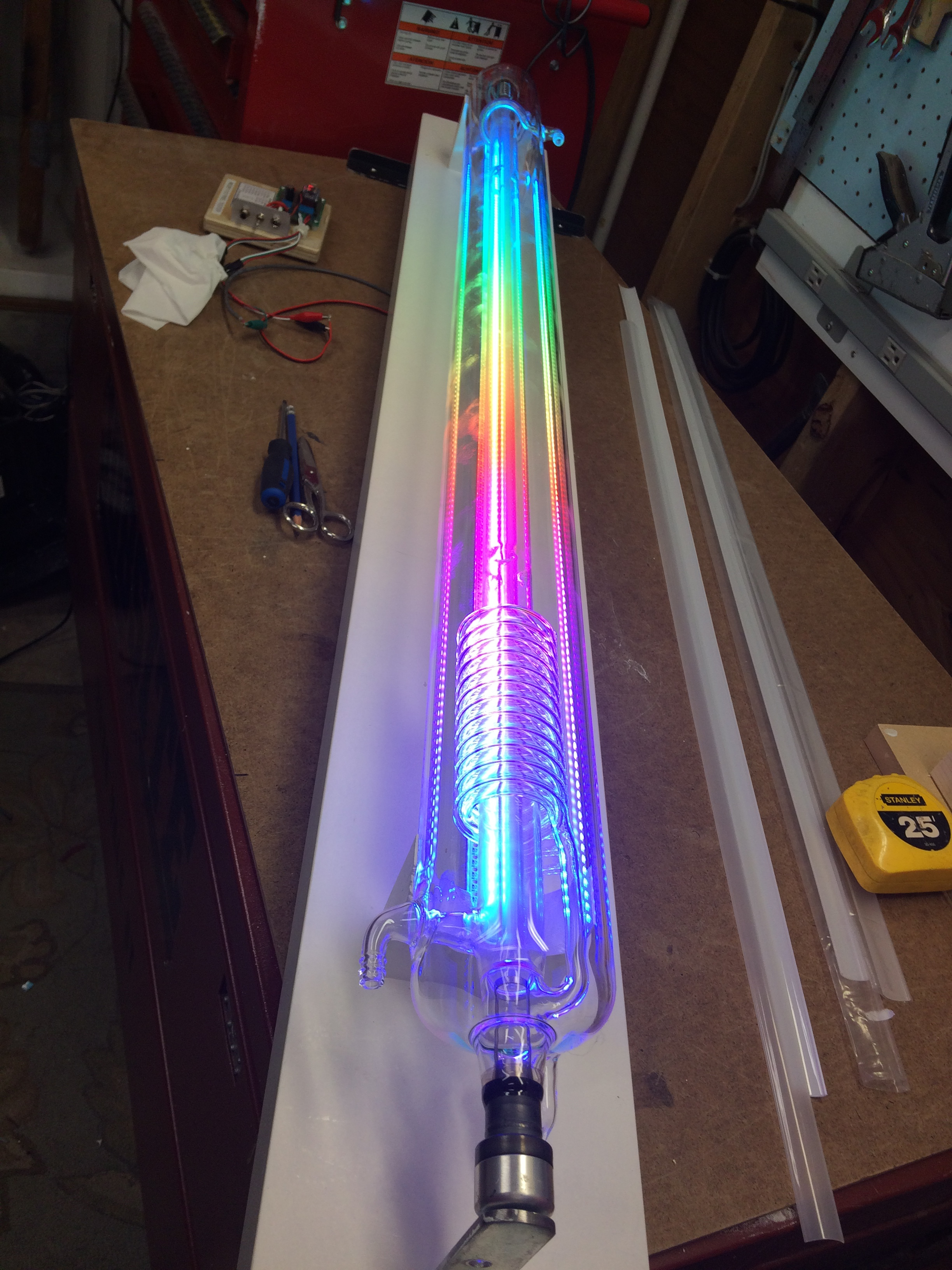
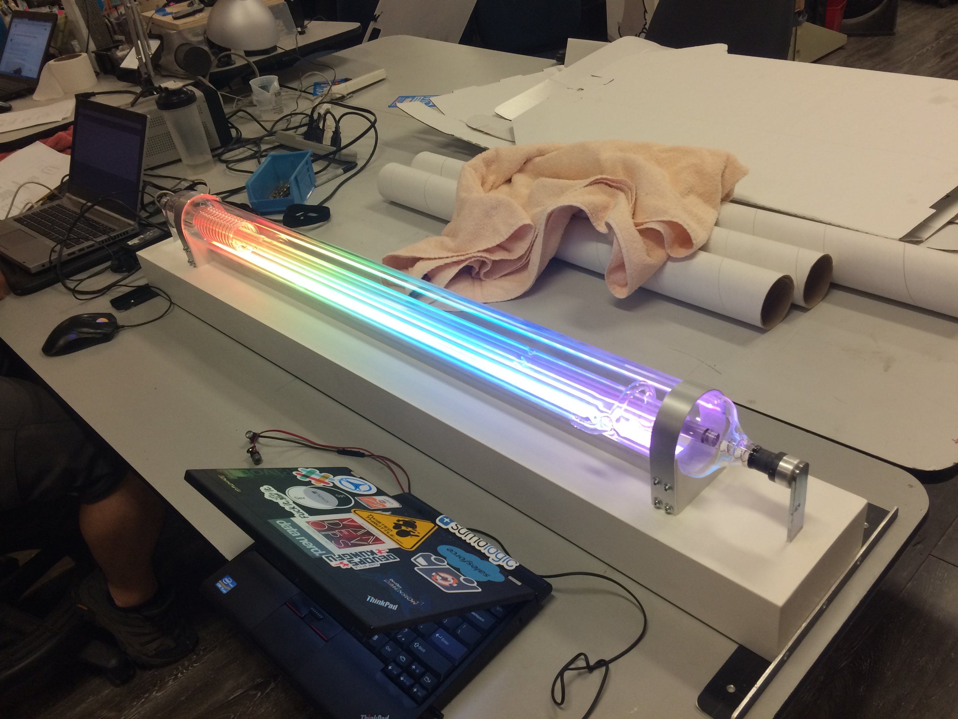
I look forward to the day we have a few tubes all LED lit like this. I imagine wearing a white lab coat and welding goggles for a mad science / rick & morty photoshoot. “VHS fusion reactor almost done!”
Started back on this project again…
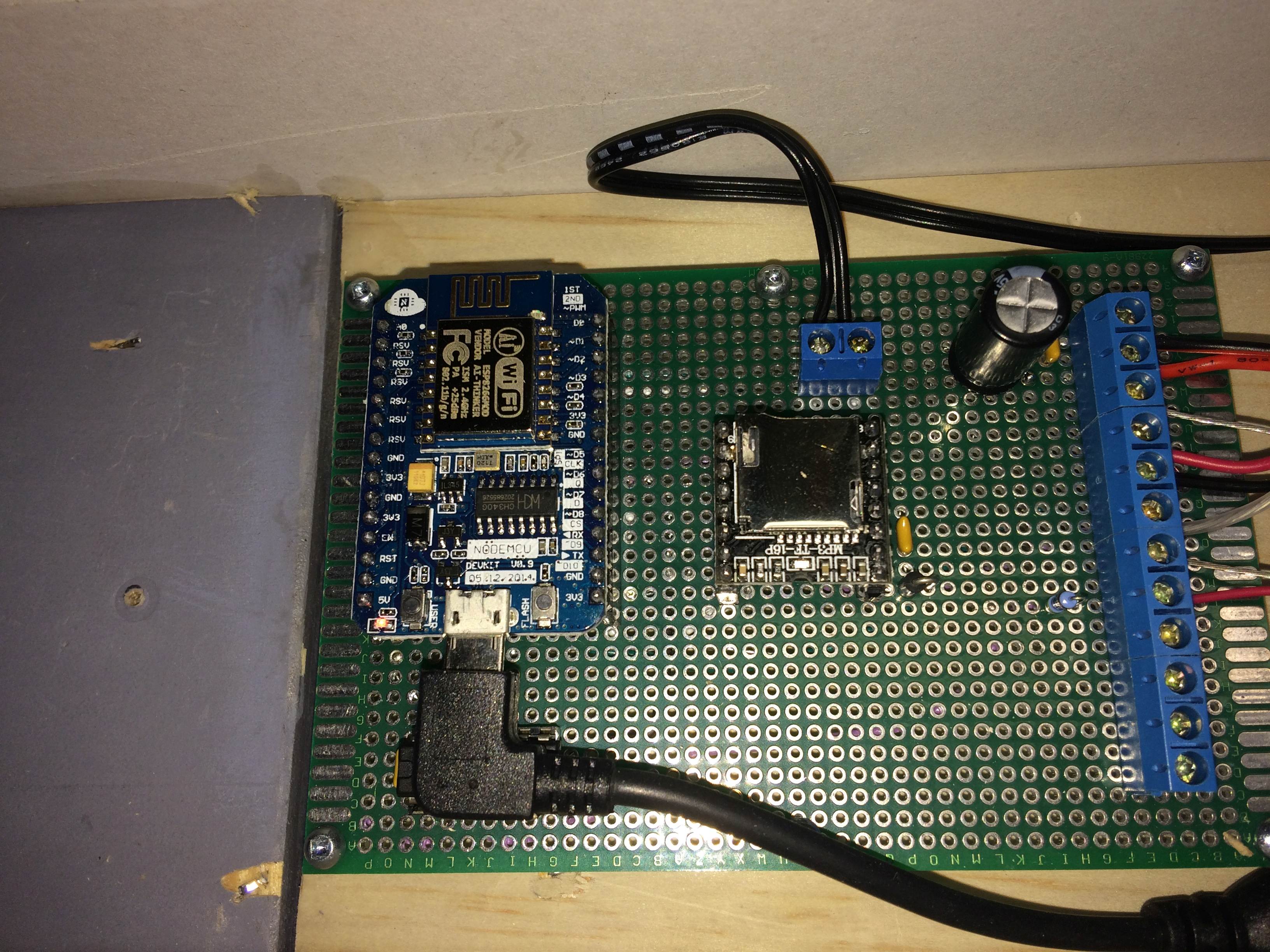
Completed the board with the sound module…
Not much else but added an extra filter cap and few decoupling caps…
I purposely left room on the board for future additions…
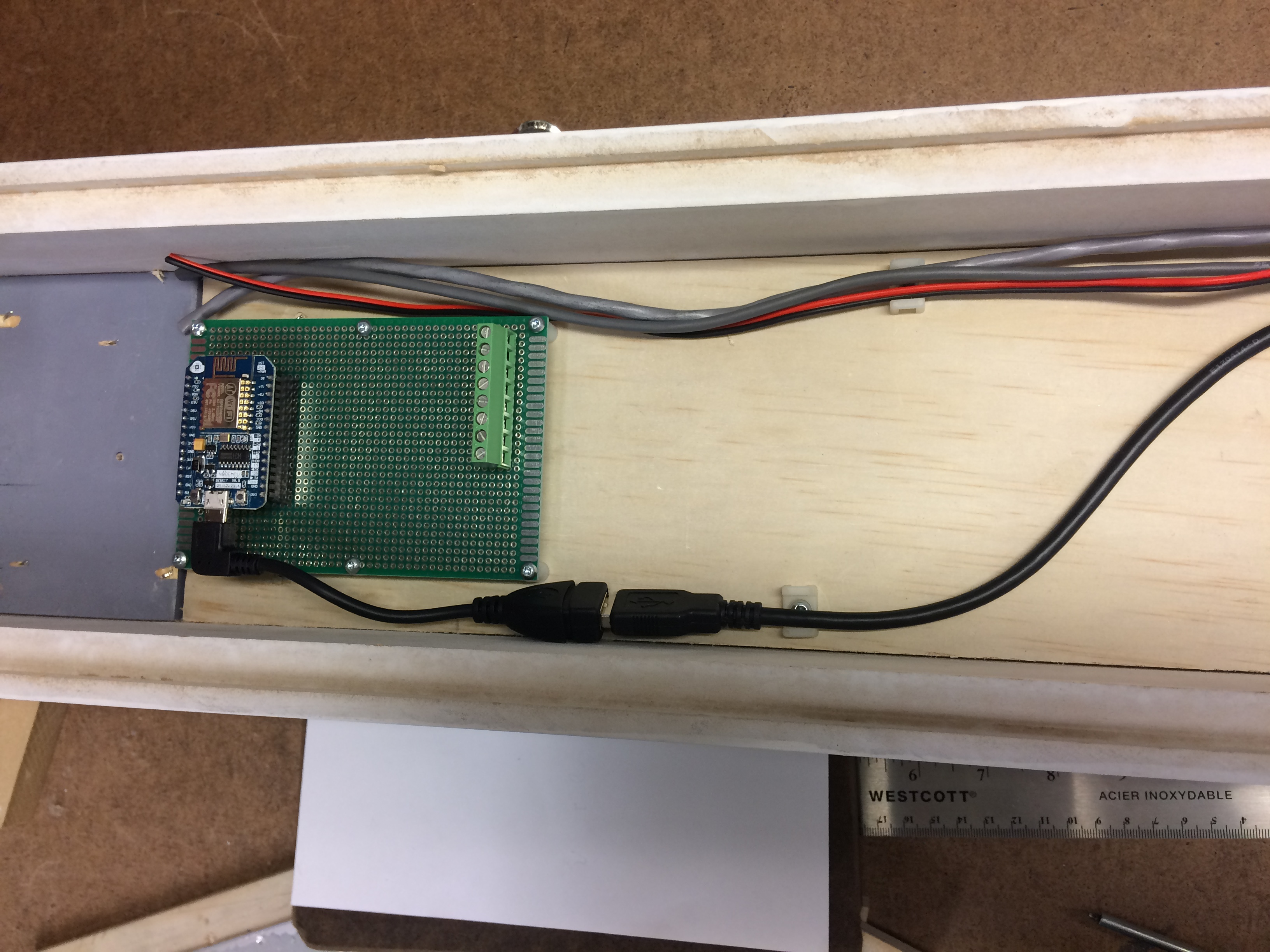
I have used a USB extension cable to extend the USB connection from the NodeMCU to the bottom of the case… Also extended the reset switch and a simple toggle to use as a mute switch.
Now I have to write some test code (to make sure my wiring is correct and the various bits all work). Next I need to find some laser sounds and load them on a SD card for the sound module. Then I can close up the back (will probably add some vent holes) and mount the tube…
Then I have to sit down and write some decent code to control it all. I will probably do something basic with the hope that someone more software oriented will make improvements.
I do have some hardware additions in mind. I had envisioned something shooting out of the end but a small laser (or even a focused LED) would not really be noticeable. But then I thought that adding a mirror ball would make the beam fly around every where and look great. But physics reared it’s ugly head when I realized that the mirror ball needs to be lit from the area you want lit up to actually see the reflections. Anyways I have plans for a remotely located mirror ball and focused LED lighting that will eventually get added…
An issue I discovered with using the USB connection on the NodeMCU (at least with the V0.9 I’m using) is that it is powered via the same USB connection. Not a big deal unless your device needs more than the 500 mA that your laptop can supply.
On some micros you can select the power via a jumper or perhaps cut a trace but no such options appear on my board.
But wait I thought… How about just cutting the +5 lead from the USB cable. You’ll still have the USB functionality but your laptop won’t try to power the laser LEDs. Since I was using a short extension cable I figured this would be easy…
I gently… gingerly… made a cut in the cable cover to expose the 4 small wires inside. Black/Red/White/Green were all there (the expected USB color code). A small inside voice said “you should double check which one is +5”… The red one of course I thought and cut away… So sure that I removed a section rather than just a clean cut…
Then I went to bed…
Next night I gave it a test and discovered the red wire was actually used for the USB + signal…
My intent is to mount it vertically at the top of the north wall column (right by the fridge)…
However I will wait till after the TV show and Makerfaire…
I have to admit my limitations with the software…
So @JDMc is going to try writing some more interesting code…
He welcomes input from all…