This image comes from a VHS member who is fairly new to PCB design:
The designer didn’t want to be named, but was happy to share the image. I think it’s a thing of beauty.
Hopefully it brightens up some people’s Friday morning.
This image comes from a VHS member who is fairly new to PCB design:
The designer didn’t want to be named, but was happy to share the image. I think it’s a thing of beauty.
Hopefully it brightens up some people’s Friday morning.
Brilliant
Truly this is genius and what VHS is all about. Well done mystery designer.
![]()
I wish I understood this
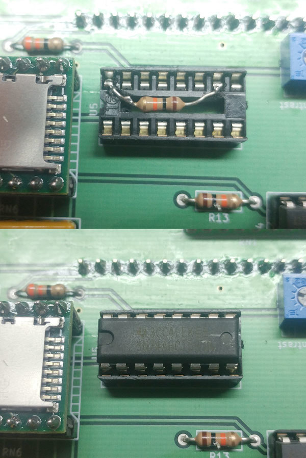
A “pull-up resistor” connects some point in a circuit to the positive voltage bus. One was needed for this chip, apparently, and not included in the design of the PCB.
Small mistakes like this are very common in circuit design, especially while prototyping, and they’re usually fixed by adding extra parts or wires to the board wherever they’ll fit. Scrape off a bit of green solder mask here and a bit there, wire the two points together. Glue an extra part to the board and run wires to it from wherever they’re needed. That kind of thing.
What’s fun about this particular fix is the way the resistor was neatly tucked away inside the socket for this chip, so that once the chip is installed the fix is invisible. It just makes the board look a little neater. I’d have never thought to do it that way myself.
Very cool, thanks for explaining that to me!
No shame to be felt by anybody here, I remember buying sockets with integral capacitors, to remove spikes from standard (i.e., known pin-outs…) TTL IC’s. Also, the above pictures illustrate why I keep a stask of 1/8 watt resistors… ![]()
This brings up another point, the technique is valid for LOW POWER dissipation situations, if you think that you could get away with it if the resistors would be dissipating a watt or more, well, better review the specs of the chip sitting on top!
All in all, a very neat correction, kudos.
This topic was automatically closed 365 days after the last reply. New replies are no longer allowed.