I’m trying to understand how to select the RC values for an IC that uses an RC network ( CD4541BE - CMOS Programmable Timer ).
The data sheet indicates:
The RC oscillator, shown in figure 2, oscillates with a frequency determined by the RC network and is calculated using:
f = 1 / ( 2.3 * Rtc * Ctc )
Where f is between 1khz and 100khz and Rs >= 10k and Rs ~= 2 * Rtc
Figure 2 is:
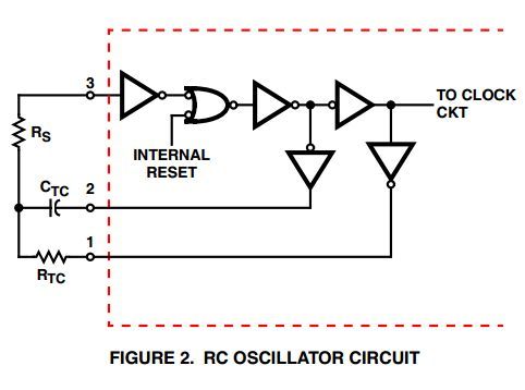
My question is about the value for Rs. The circuit uses a potentiometer for Rtc (10k) in order to adjust the timer (Rs is a 20k resistor). However, according to the data sheet, Rs should be around 2 * Rtc. If using a pot for Rtc, it means the design rule of Rs ~= 2 * Rtc is violated for at least 50% of the range.
Question: Is Rs mainly there to provide a high impedance path for the feedback loop? or does it take part in the frequency calculation as well ( i.e. Rs should change with Rtc in order to have a predetermined frequency )?
Empirical testing shows that Rs does indeed affect the frequency… 
So, according to the schematic in your post, one end of Rs is connected to
the buffer input and should be modelled as an open circuit, basically
(~10^12 ohms, crazy high).
For it to have any effect on the frequency, you’d expect there to be some
significant leakage in the input, so I took a look at the datasheet. It
doesn’t have any input impedance specified, so you wouldn’t expect it to
matter.
I also worked out the logic on that snippet you posted, and it didn’t make
any sense!
Googled for a drop-in replacement to see what other manufacturers were
doing:
https://www.fairchildsemi.com/datasheets/CD/CD4541BC.pdf
Also no input impedance listed, but that schematic is different! The TI one
is missing a bubble, they totally got it wrong and it makes the circuit not
work out as drawn.
tl;dr I have no idea how to solve your problem, but TI should stop hiring
interns and maybe try a replacement from a different manufacturer?