Raspberry PI, TTL to RS232 and RS485

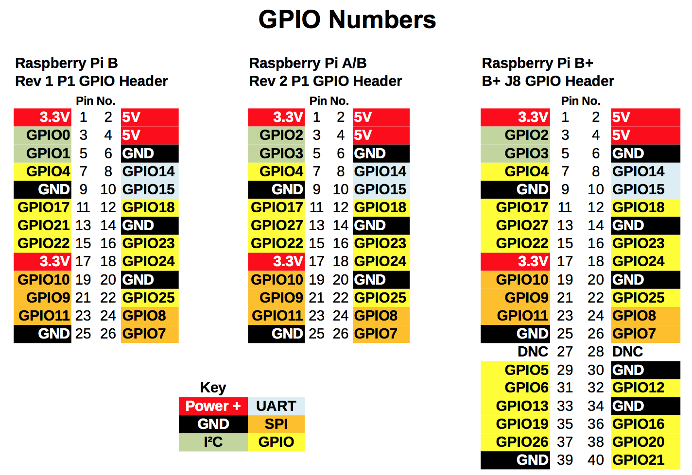
I am designing a Raspberry PI (RPi) shield, that uses one of the UARTs (TTL) on the RPi, to talk to a MAX1487 chip. This enables the RPi to talk RS485 using the built in UART. I have this working on a bread board now.

I want to add the ability to switch the port from RS485 to RS232 in software on the RPi. Ideally they would both use the same DB9 port.

The MAX1487 (RS485 chip) has an enable pin for the TX and RX that I can use to enable or disable the the RX/TX of the chip. I can use one of the GPIO pins for this. Now I am looking for a chip to do the RS232 part that also has an enable and disable pin.

Preferably I would like to use one chip that has both RS232 and RS485 build into it with a single GPIO pin to switch between the two but I haven’t found a chip that does this yet.

I like making my life complicated…

My questions are:

  • Is there a TTL to RS232 with an enable pin for the RX/TX pins ?
  • Is there a single chip that does TTL to both RS485 and RS232 ?
  • How would you do both RS485 and RS232 on the same port using the RPi UART?

No, I can not just use USB to RS232/RS485 converters.

No
rs232 is full duplex

rs485 is half duplex, can be connected in a bus structure
rs422 is full duplex

if you don’t care about the rs485 bus ability, perhaps a
rs232 rs422 solution be acceptable?

It looks like the LTC1387 may work for you: http://www.linear.com/product/LTC1387

Cool chip. The inputs are 3.3v tolerant, so you can control those pins
directly from the GPIO, too.

lots to choose from
RS232 and RS422/RS485

http://www.digikey.com/product-search/en?pv183=2475&FV=fff40027%2Cfff801a4%2C1140003%2C9080034%2C9080036%2C9080038%2C908003b%2C9080040%2C9080062&k=rs422&mnonly=0&newproducts=0&ColumnSort=0&page=1&stock=1&quantity=0&ptm=0&fid=0&pageSize=500

If you specifically want RS232 and RS485,
http://www.digikey.com/product-search/en?pv578=54&FV=fff40027%2Cfff801a4%2C1140003%2C2dc09ab%2C9080034%2C9080036%2C9080038%2C908003b%2C9080040%2C9080062&k=rs422&mnonly=0&newproducts=0&ColumnSort=0&page=1&stock=1&quantity=0&ptm=0&fid=0&pageSize=500

Do you care about surge isolation?

I have blown a many many rs485 transceivers due to signal line surge.
For this reason I would recommend exar.

http://www.digikey.com/product-detail/en/SP330EEY-L/1016-1977-ND/4555654
http://www.exar.com/common/content/document.ashx?id=21451&languageid=1033

Yes, In this application it is a requirement,

Thank you everyone.
I will investigate these chips, order a few and report back in a few weeks.
You guys rock!

The single TVS diode show in the first figure is a good idea
You use an equivalent part of course
PROTECTION SCHEME 1. TVS

For a heavy vehicle application I implemented the second figure. That is
good enough unless regular surges are expected. The Diodes are degraded by
regular surges. The only thing capable of handling regular surges are
TUBES!!!
PROTECTION SCHEME 2. TVS/TBU/TISP

Here is the pinout for the different versions of the Raspberry PI

The RS485/RS232 chip needs the UART (GPIO14 and GPIO15)

I am planning on bringing the SPI and I2C pins out to headers just in-case I need them in the future.

I need two additional GPIO pins for enable/disable and mode selector (RS485/RS232). I would like this board to work with all version of the Raspberry PI header. This leaves me with a choice of a few different GPIO pins that I could use. GPIO4, GPIO17, GPIO18, GPIO21, GPIO22, GPIO23, GPIO24, GPIO25

My questions are

  • What should I consider when selecting what two GPIO pins to use for my Raspberry PI shield? Do you have a suggestion on what GPIO pins I should use?

  • I know that the SPI pins should be brought to a 2x6 header. (SPI connector pinout). Is there a standard or a common practice for the I2C header that I should use?

For GPIO selection, it may be important to know how it acts on RasPi
startup or shutdown.

Check the alternative peripheral registers, here:

Page 102 is what you care about.
Select pins that are pulled high or pulled low in the way that you want.

Keep in mind that the datasheet is referring to the Broadcom’s GPIO, not
the Raspberry Pi’s.
See here for a table that gives you equivalent pins on the RPi’s GPIO:

http://elinux.org/RPi_Low-level_peripherals

Good point! I didn’t think of that.
I will use a GPIO that will disable the chip on startup to prevent taking down a RS485 network on start up.
Thank you !

New requirements from up high. I now need to support TWO serial ports. One dedicated RS485 and one software switch-able RS232/RS485 port.

From the looks of the Raspberry Pi 2 pinout, there is only one UART available (GPIO14 and GPIO15).

I found this kickstarter project ( uart-hat ) while researching on how to add two UARTs to a Raspberry PI. Its one of the worst Kickstarter videos I have ever seen. They are using the I2C bus to add an additional UART.

I found SparkFun I2C/SPI-to-UART Breakout - SC16IS750 that should let me use the I2C bus to add additional UARTs to the Raspberry PI 2. I have already ordered this board.

My new questions are:

  • Does anyone have any experience with using a UART over a I2C bus? Any problems? Any gotchas that I need to worry about? Speed, reliability, etc…

  • How do I tell Linux that there is a serial port on the I2C bus that it can use?

I am not sure what the best tool is for embedding a PCB board design in a talk post
Here are some images of my board design.

I am looking for feedback on my design.
Please tell me if there is a better way to share a PCB design while looking for feedback.

Here is a better image

Parts list
R1,R2,R3,R4,R5,R6,R7,R8,R9,R10,R11,R21 = 100ohm. R1206 package
R12,R13,R14,R15,R16,R17,R18,R19 = 10k ohm R1206 Package
R20 1Mohm R1206 Package

SW1 = Digikey Part Number: 450-1420-ND

U1 = SP330E TSSOP24 PACKAGE
U2 = MAX483 SOP08 PACKAGE
U3 = SC16IS750 QFN24 PACKAGE
U4 = AP3003S-5.0TRE1

X1 14.7456m Mhz HC496/S package

D1,D3,D5,D7,D9,D11 = Digikey 516-1417-ND
D2,D4,D6,D8,D10 = Digikey: 516-2105-ND
D12 = 1N5822 C2992 PACKAGE

L1 22uH LM4532M pakcage

P1, P2 = DB9 connector. Digikey 609-4003-ND
P3 = Digikey 609-3907-ND
P4 = 40 PIN (20x2) 100 mil spacing female pin header

C1 470uF 50v E5-13 PACKAGE
C2 220uF 6v ef-8 PACKAGE
C3,C4 18pF C1808 PACKAGE
C6,C7,C8,C9,C10,C11,C12 0.1Uf SANYO OSCON A5 PACKAGE

Overall the layout looks pretty decent to me.

  • You can move the trace below C10,C11 up to their pad gap and improve the ground path for them (which is hard to tell if it even exists :P). Similarly rotate C6 180 degrees.
  • Do all the DIP switch related passive have a valid ground path? It looks like some of them might be sneaking through a very tiny sliver of ground plane between the connector pins. I would probably have routed the signals on the bottom layer and brought them up on vias to keep the top layer groundplane clean.
  • I would definitely get rid of the huge orphaned ground fill that loops around from the left of the board over the top.
  • Your V+ trace looks like a loop. I don’t think you want this. I would remove the trace running up the left side of the board to C5.
  • The layout around U4, which I assume is a switching converter, isn’t great. Tighten those current loops!
  • These are both RS485 transceivers right? I don’t see termination resistors for either port, and most drivers aren’t internally terminated. This might also pose an issue for your switching scheme…
  • Finally RS485 is typically terminated into either screw terminals or RJ45, not DB-9. It’s probably a good idea to at least include the screw terminals somewhere.
3 Likes

Updated board v0.3

We have had to make a few chip changes as the quantity and availability on digikey. I would hate to have a chip get discontinued while we still need to produce these boards. We have also changed as many of the elements as possible to surface mount to make it easier on the assembly house.

Other things that have changed

  • AC/DC current for power, Mainly we wanted to accept 24V AC, as that is available in a lot of the places that we want to install this board but we want to ship with a cheap power supply of 12V.
  • 5V believable on the serial port, enabled via a jumper. This will not be connected by default but will allow us to wire a bias resistors]2 when they are needed. It also gives us some options for future projects.
  • Connecting the RX and TX leds to the RS485 and RS232 lines to show message flow.

The next step is to get the board files reviewed by our assembly house for pick and place house to see if there are any other improvements we can make. I expect that it will take them 2 weeks before we get any feedback.

I jumped the gun and ordered 3 prototype boards from https://oshpark.com that will take a few weeks to get here. I will then hand solder them and test them. I expect that there will be changes from the assembly house but I just couldn’t wait.

As always, feedback is always welcome.

I passed feedback from @ktims, @Jarrett, @TomKeddie on to the person that is creating this board.

We have found that this should always be external to the device instead of internal. Tech on site want to know when a termination resistors is enabled by physically looking at the connection.

I also gave consideration to this point and instead of having screw terminals we are using DB9 break out boards (considerably cheaper then these ones). I did this for a few reasons; To reduce the different types of parts needed to assemble the boards and thus reducing the assembly cost. One of these ports will be used for both RS232 and RS485, most customers want a DB-9 connector for a RS232 connection.

Is he running DRC on the board? The supply track looks really close to the right hand mount point of P1.

What is “DRC”? I am guessing not,
I have told that there is a few issues with this board already.

DRC = Design Rules Check. The board design software can check if the design meets rules, such as spacing between traces, clearance from the edges, etc.

All the cheap pcb makers provide an eagle DRC file that will check their design requirements are met by your eagle pcb design. You should always make sure the ERC (Electrical Rules Check) passes on the schematic and the DRC (Design Rules Check) passes on the pcb (passes = you understand any errors or warnings are not important).

You can get the drity pcbs files from DirtyPCBs.com from that you could tweak the rules to match your manufacturer.