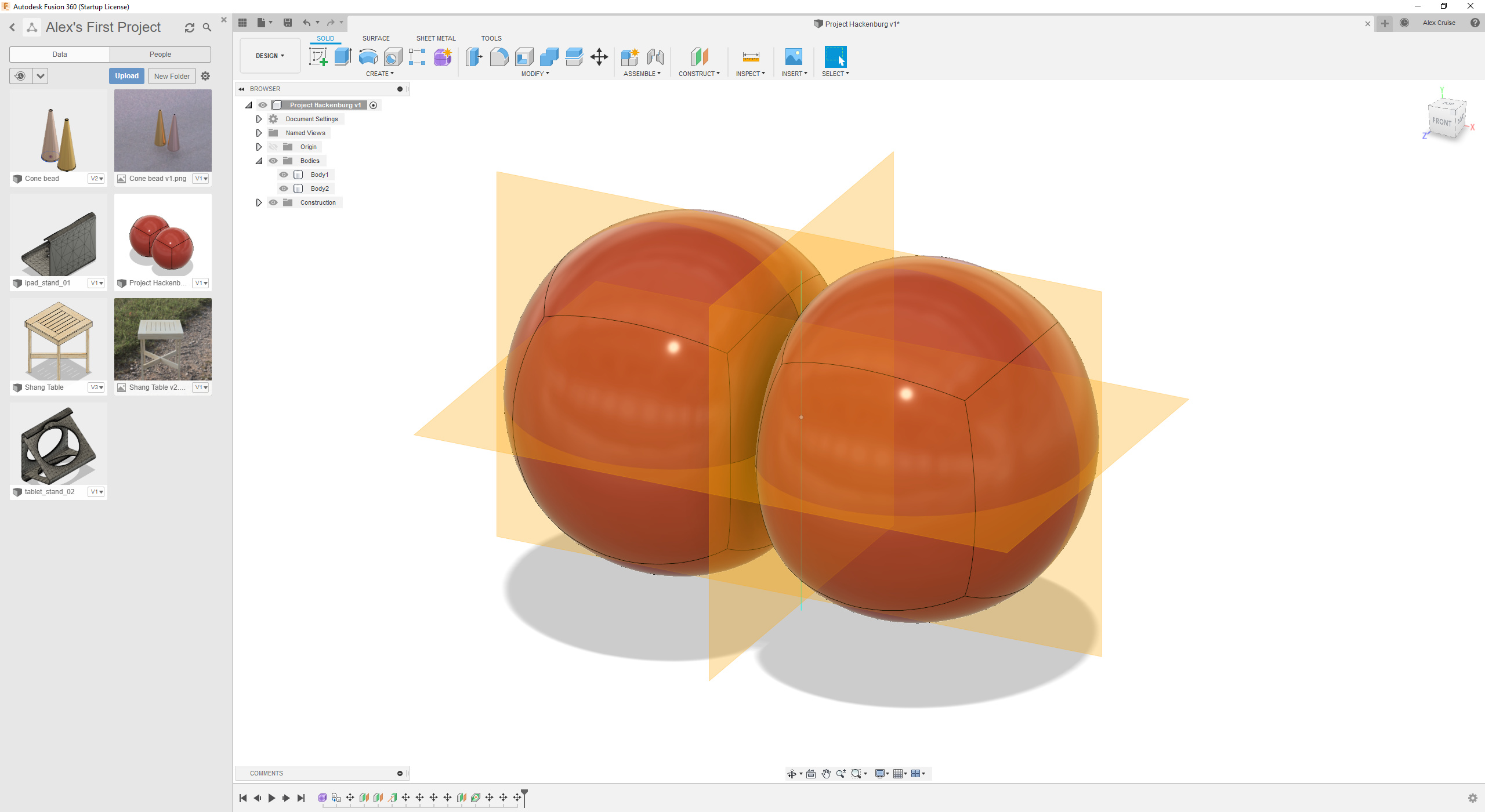
I’ve been thinking about this for a long time… I ordered a dozen or so 1m diameter balloons a few weeks ago, and I managed to get two smooshy spheres modeled up in F360, so I guess I’m off to the races. ![]()
2 Likes

Well, not too bad for an evening’s work. A lot of this is kinda janky but the first version of anything usually is.
Some design notes:
- The balloons are supposed to be about 1m diameter
- I think the equator strap should be something light and rigid, maybe bent plywood?
- The upper and lower straps are modeled as canvas, which I think makes sense
- The brackets that join the canvas straps to the equator are modeled as bent aluminum, but since I messed up my scale from the beginning, they’re too thick. Next version will be to scale.
- Now that I’m looking at this in the cold light of midnight, I may want the holes in the equator brackets to be offset diagonally instead of aligned horizontally, to avoid stress fractures
- I might do another version with three balloons–from what I’ve read, you can get about 400g of lift from a 1m diameter balloon filled with Helium.
- Helium is precious and also way too safe, we should totally use Hydrogen instead.
- The motors will probably be attached to the equator, to optimize thrust angle for horizontal flight. Two might be enough. If we can get reversible speed controllers and props, we could get away with only a 180-degree gimbal, and use cheaper servos.
- The battery, electronics and maybe some ballast should probably be in a gondola hanging from the bottom, to provide self-righting in the roll axis.
- The whole thing will be tethered 190% of the time, I’m foolhardy enough to actually build this but I’m not an idiot.
I could use some help with:
- prop selection and duct design (obviously the ducts will be 3D printed, but 3D printed props are probably too rough
- electrolysis of water to make hydrogen
Next steps:
- I guess I’ll order a couple of these 180 degree 9KG servos
- Redo the CAD project to be to-scale and generally nicer
- Do another version with three balloons
4 Likes
Looks like these ESCs will work.
1 Like
Helium is precious and also way too safe, we should totally use Hydrogen instead.
![]() really getting the Hindenburg spirit here.
really getting the Hindenburg spirit here.
Old LiPo packs could be a “convenient” source of hydrogen. You can make this thing self inflating!, Just need a circuit to short the battery, and some thermal management. ![]()
(In the interest of the internet sarcasm rule: you shouldnt do ^^^, it ![]() )
)
2 Likes
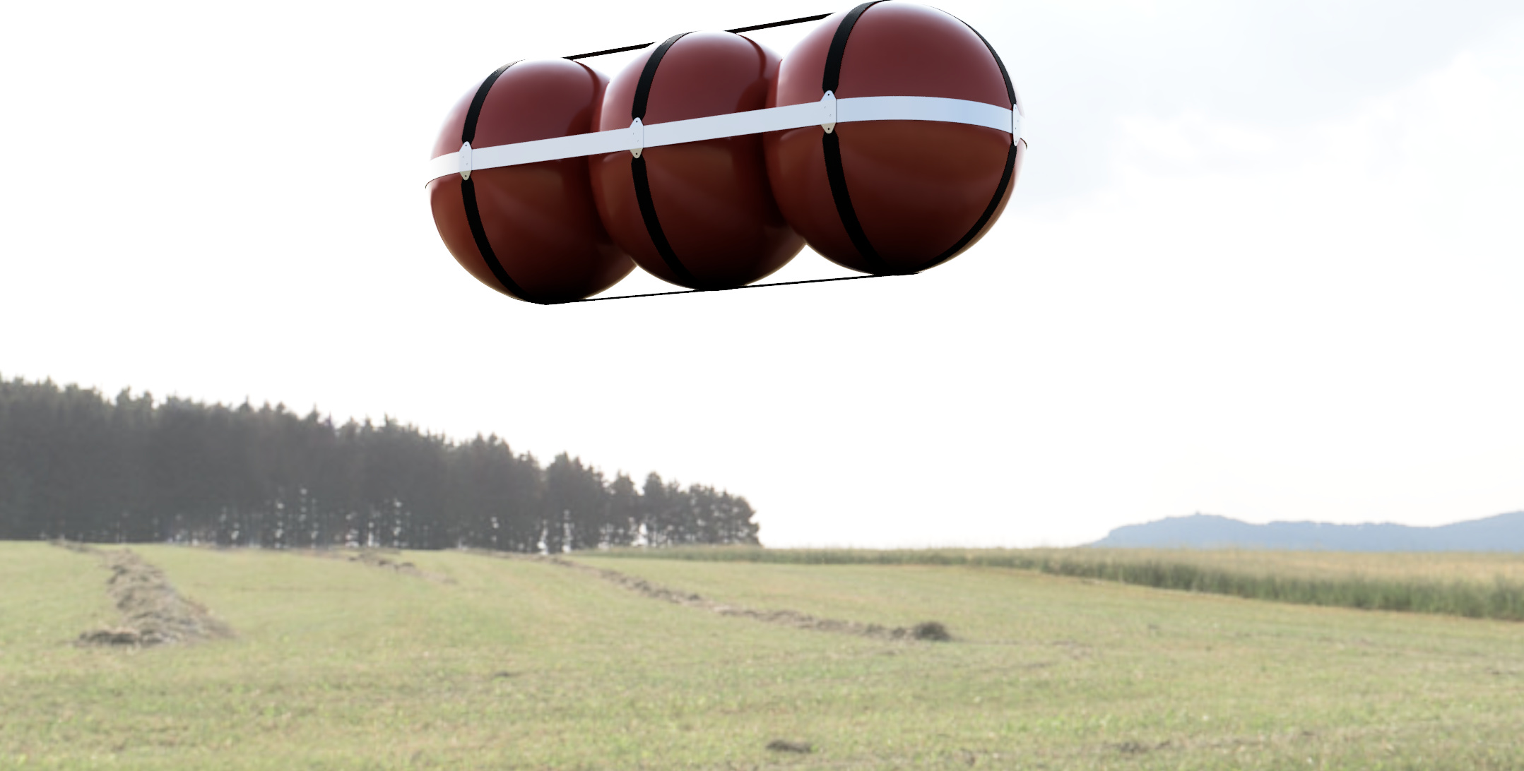
Three-balloon version, to scale (1m diameter balloons)
Next:
- Design a gondola. The non-equatorial straps aren’t rigid, so the gondola might need to be braced against the equator with four thin rods
- Design one-axis, 180-degree gimbaled motor mounts. I ordered two of the servos linked above, that will help.

Forgot to mention last time:
- The non-equatorial straps should be lightweight canvas or nylon webbing, and be riveted where they cross
Trying to keep straps aligned where you want them on curved surfaces is a bit of a nightmare, even if you think you have them riveted perfectly. I’d recommend some end cups or a portion of net, perhaps?
1 Like
Yes! I was worrying about that last night, and @JDMc asked about balloon rigidity on Slack too… Some light & tight netting around each balloons, fastened to the straps, would be a good place to start I think.
1 Like
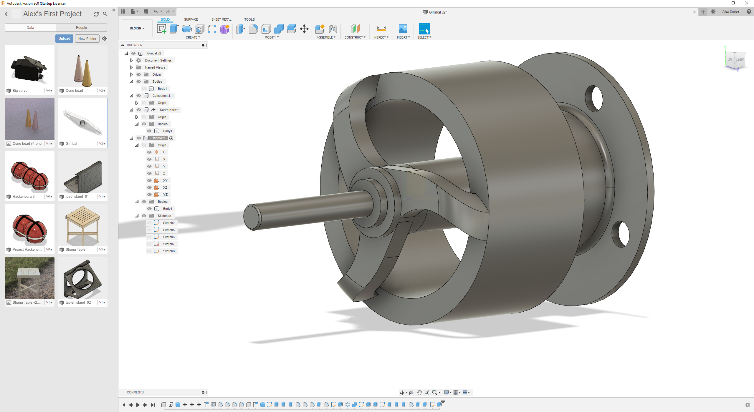
Duct with motor mount
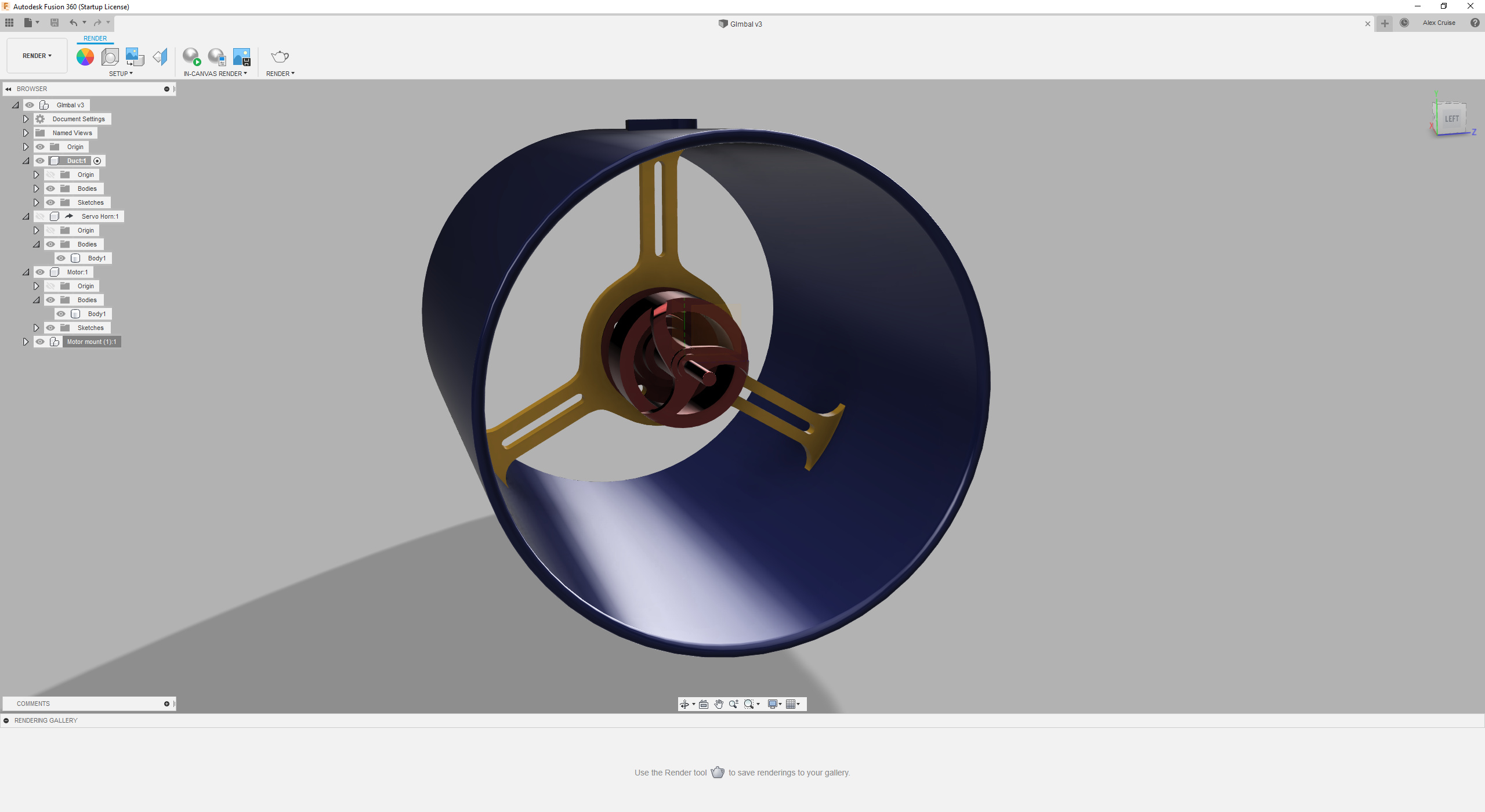
This design assumes the servos I ordered are actually 180-degree as advertised, and I can mount the ducts right on the servo horns.
Next up, I guess I need to design the bracket that holds the base of the servo, and attaches the motor assemblies to the equator band.
edit: hmm, I probably put the motor mount right in the centre of the duct, but it should probably be moved back a bit so the centre of mass of the whole assembly including the motor is in line with the servo mount… ![]()
Thinking about this some more…
- I think I want to have the motor mount’s support arms to be one diameter, collinear with the servo mount, instead of three radii; the whole assembly should then be more robust against the torque from the servo.
- I should also spread out the area where the motor mount’s feet land against the inside of the duct, to provide a bigger glue/screw surface. Just need to remember to keep them clear of the prop.
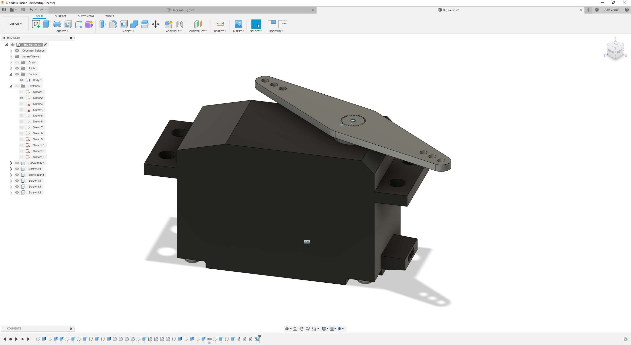
My servos came today… I haven’t tried them out but I’m pretty sure they’re not 180s… They have a lot of torque though, so I might just put a pair of multiplier gears between the servo and the gimbal.
I need to redesign the motor mount to be two arms instead of three, relatively thicker, and oval in cross section (because bidirectional airflow), use some gusseting to spread out the load from the arms to the motor mounting plate, probably continue the arm thickness behind/through the motor plate, and design bigger feet for where the motor mount arms land on the inside of the duct.
Also need to find a design for bidirectional props, but this is going to be a very slow aircraft, so efficiency is not paramount. ![]()
1 Like
I was walking with my kid last night and talking about the various design challenges here… They had some really good ideas:
-
For the problem of keeping the longitude straps fixed in place on the surface of the balloon: velcro! Sew pieces of the fuzzy side to the inside of the straps, and stick pieces of the prickly side to the balloon surface. No netting needed!
-
They suggested a modular approach to several things, including the equatorial band. Instead of trying to make one magical 3mx1m bent plywood oblong shape, we could just make two curved end pieces and reuse them with the 2- and 3-balloon variants, with different lengths of detachable side pieces as necessary. I’m even thinking that the equatorial bands don’t need to be rigid. The straight side equator band pieces can hang from the upper longitudes, and the lower longitudes can hang from the side equator pieces; the ends of the equator can just be straps. I might need a bit more tension support with nylon cord…

I tested one of the servos, it’s only about 110 degrees.
In related news:
- My servo tester can’t drive enough current to push this servo very fast
- My new tiny oscilloscope works
![]()
1 Like
Your servo tester is only sending a signal, not power. Either your power supply can’t supply enough current, or the servo itself is stalling out and needs (higher voltage / better motor)
Well, the power is passing through the servo tester. My power supply is a little Boldport thing with a linear regulator designed to hang off the side of a breadboard, I wouldn’t be surprised if it’s not providing enough oomph. ![]()
Servos can draw a few amps on startup. I found wiring a 4700uf+ sized capacitor to a spare 22 gauge servo plug and plugging it in next to the servo helps smooth things out a bunch.
This topic was automatically closed 365 days after the last reply. New replies are no longer allowed.