I have an ESP32 running the MicroPython firmware and have met the blinkenlights, said hello to the world, all the usual goodies. What fun. I am now attempting to connect to a PN532 via SPI interface and I am running out of sticks with which to poke it. If any of you fine folks have experience setting up that combo, I could use a hand.
What I have:
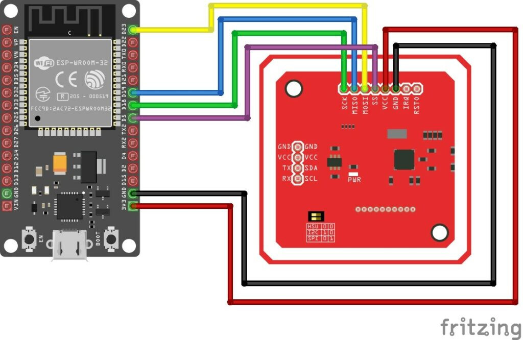
I have an Elechous PN532 NFC reader board [manual here].
I have the MicroPython port of the PN532 drivers and demo code from here
I have read this post where it would appear the OP is connecting theirs the exact same way and have adjusted the spi_dev assignment to match theirs.
What I get:
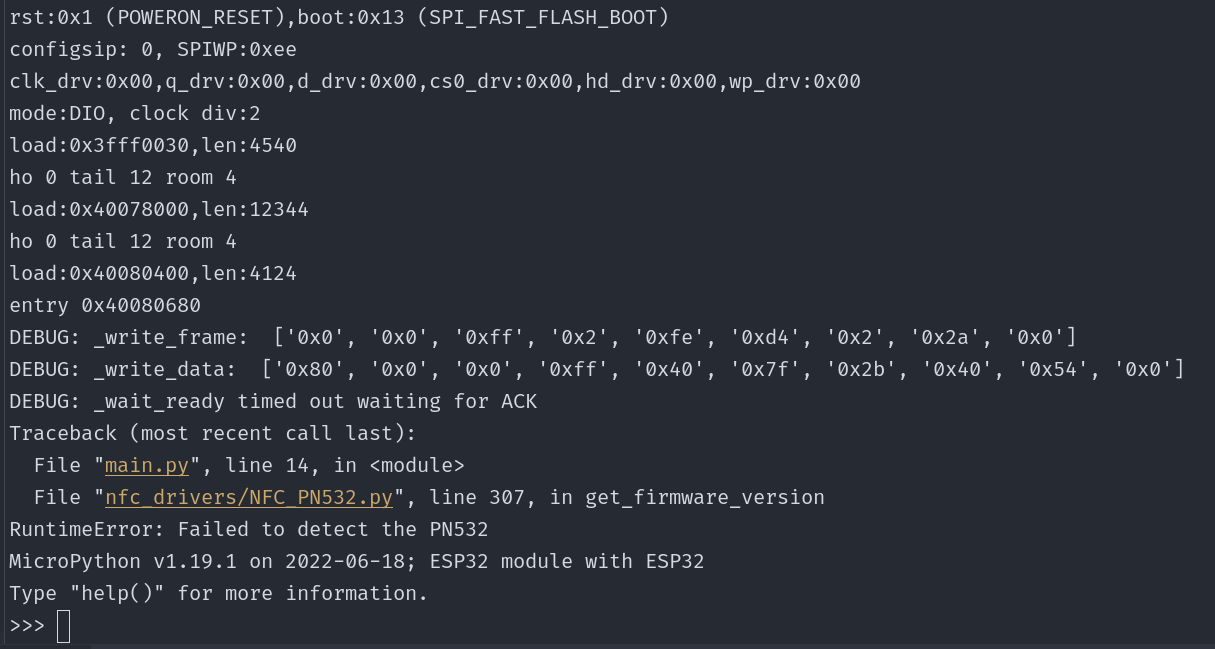
Traceback (most recent call last):
File "main.py", line 18, in <module>
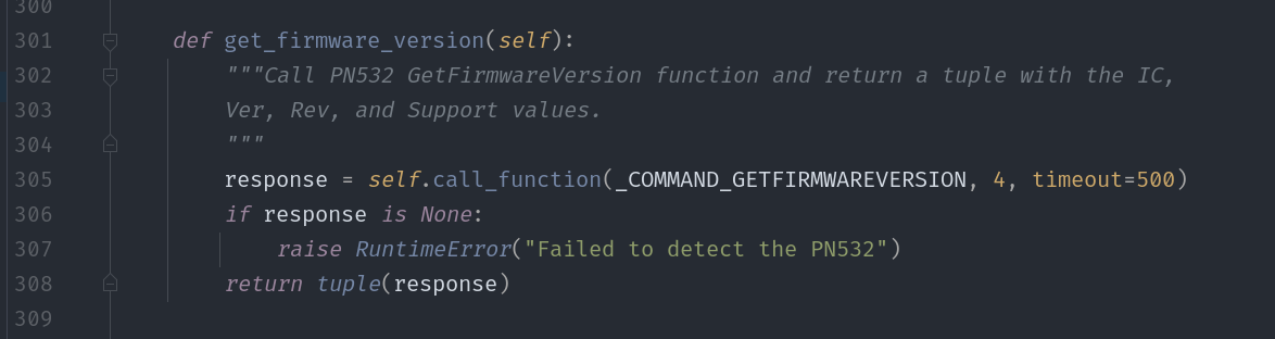
File "nfc_drivers/NFC_PN532.py", line 307, in get_firmware_version
RuntimeError: Failed to detect the PN532
What I’ve tried:
Debugging indicates that it gets into the _wait_ready method then times out on the while loop. I flipped it to a while True just to make sure it wasn’t a race condition and it still fails.
The Elechous manual [linked above] says that this board uses 115200 baud so I changed that in the sample code’s spi_dev assignment
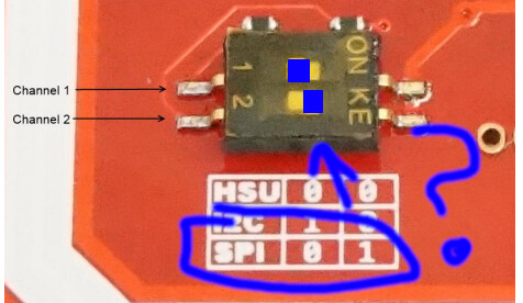
I have frankly tried every permutation of the two DIP switches to set SPI mode, but are these the right positions?
I’m sure you’ve done this already - but just in case, I’d doublecheck the pinouts. What board was that demo code running on originally as D5 on that may not actually be the D5 as labelled on your ESP.
Edit: sorry not sure if that is much help. The PN532 has a built-in level shifter right? i.e. it’s not a 3.3 vs 5v issue?
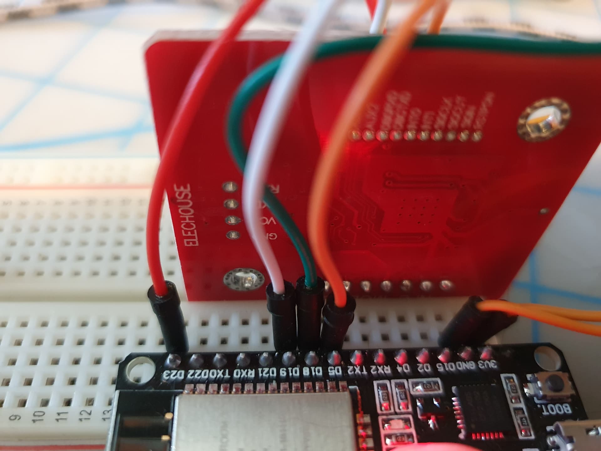
I take that back, I am willing to rule out faulty connections. I’ve also used a continuity tester from pin to pin (leads on the back soldered side of each connected pin), so it’s not the wires, connections, breadboard, bad/faulty solders in the headers, etc.
The thing that jumped out at me there was the first argument of the SPI declaration. The example github and linked post both say SPI(1), while the following post says SPI(2). Generally those first arguments are the SPI peripheral number, for microcontrollers that have a few SPI drivers at their disposal, usually with different pin configurations.
That could very much be it. I misunderstood the purpose of the “id” parameter in the SPI call, and set it to 1 thinking it was like dev1. That makes sense, and I appreciate your explanation. I’ll try it out this afternoon!
Yes, that forum post (and the one right after it) were the ones I was trying to link to but screwed up. Unfortunately, the SPI id is not the (only) problem.
Everything looks good to me, now. At this point I usually recommend the $10 Amazon / AliExpress logic analyzer, which is honestly the highest utility-to-price ratio of any tool I’ve ever had.
I’m powering the ESP32 off the USB connection to my laptop (power and programming it off the one cable) and the PN532 off the ESP32. So that’s possible? IIRC USB ports are rated at .5A?
Alright, well, my cheapo Amazon one came in. I have no idea what I’m doing with hit yet, but I’ll start poking at it and see what I can find. Cheers, folks.