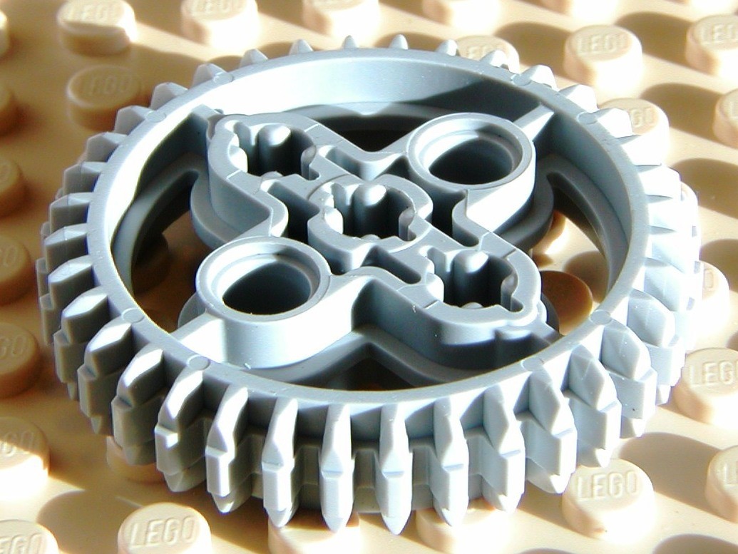
The larger gear has an 8mm hole and a 48mm pitch.
The smaller gear has a 5mm hole and a 16mm pitch.
I’d like to know how to generate them myself so I can repeat the process.
Getting a finished gear design that I can print is a distant second.
I’m also open to other suggestions how to achieve my goals. Pics in the link explain what I’m trying to do.
I wasn’t sure if it’s model that can be manipulated to suit your specs.
Bores can be plugged as long as you get the desired gear profiles that you
require.
Try making your gears like this Bevel gear - Wikipedia the process would be, build a flat topped cone, populate the edges with teeth at a 45 degree angle. The problem you’re having is that you’ve got teeth that are angled, the ratio of large face to small face on each gear head is different, so you get tapered teeth. By going with this other method, you change your teeth to being a uniform shape, you use the exact same tooth on the small gear, just less of them.
If you’re not sure how to do it in cad, I can attempt to do it in Maya for you, or at least a mockup. I’d just need t know the other dimensions.
The trouble with this gear is that it’s not actually a valid involute tooth profile due to the smaller gears meshing with a larger gear which already has it’s angles set by a 90 degree mesh with a gear of the same size.
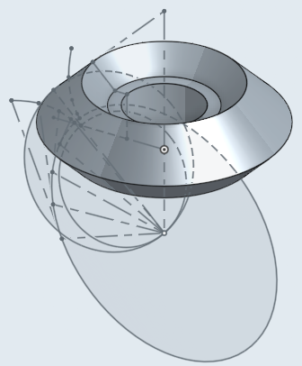
The correct way to make involute bevel gears like this is to make the two gears have the same vanishing point. If you were to replace the gears with rollers they would be two cones that come to a point at the same location.
Okay, all that said as soon as you leave the bevel involute gear model, you can easily make one. In truth, the tooth model is very similar to an involute gear by fixed at 45 degrees and when the tooth is looked at on-end it’s curved in at either end of the tooth area. What the gear becomes is a compound sphere segment - okay, that’s just a fancy way of saying it’s rounded.
There are a few ways to model this. The first is to model your involute curve on a plane and loft it to a point, same as you’re doing. You then will use a turned cut to select only the meshing portion of the gear. You then have to apply a small bevel (say 2mm on one side and 0.4mm on the other) so that it narrows either end of the tooth profile and then, if you’re feeling fancy, round off the interface between the tooth and the bevel, but printing will do a bit of that too so you may not have to.
See:
The other way to model it is more computationally costly but produces perfect results. Take the gear that you’re going to be meshing with, locate it to where it’ll mesh, then array it so that the movement of the tooth against the blank gear matches the movement exactly. You then do a subtraction of all of the models along the movement curve into the blank. Once you have that, you can array the cut profile… note, though perfect I do not suggest doing it as… it’s a really slow process. Note that this is a very good way of designing any gear - just slow.
Also, to add; You may need to change your pressure angle on the smaller bevel gear to match the profile correctly. Lower it by about 30% (so 30 degrees you can drop to 20 degrees). This is because the angle, though both 45 degrees, doesn’t match quite right and you can tweak it. This will elongate the curve outwards, making the gear have more tooth to engage the larger gear.
You may also adjust the adendum to lengthen the profile tip a bit further but only until it gets near the root diameter of the meshing gear. You can actually increase the adendum/dedendum (tip length/root depth) calculations as you aren’t using these gears for heavy weight applications… note that if you’re meshing with an off-the-shelf gear you need to match to that one.
All this is so complicated. I’d be much happier ordering exactly what I need from SDP or a chinese supplier.
There my problem is understanding the SDP catalog. I can’t make sense of the options and I really don’t want to order the wrong stuff.
I think i mentioned this before; this is not a valid gear. You can’t order it due to that.
Design the gear like you had done. Use a lathed-cut to make both inside and outside 90 degrees to the direction of the tooth. Bevel the edges of the tooth profile so that it’s thinner at the outside and inside portions of the tooth.
You’re 90% of the way there already in solidworks. Just take the bevel tool, make it uneven using distance/distance (as apposed to angle/distance) then set it to something like 0.5/2.0 and select each of the end-edges of each of the teeth. If it selects the wrong direction, there’s an arrow or a dot (depending on SW version) that you can hit to flip it’s direction. Keep selecting each of the edges one by one and then apply it. The end result should work pretty well.
This was the best [parametric bevel gear generator][1] that I could find when I needed bevel gears. You use OpenSCAD to generate STL’s of the gears you need, and then can import them into another CAD program to work on them more. Take note that some of the terminology used in the code is not standard.
As far as modeling one yourself, I learned enough about involute bevel gears to know that all the blog posts and instructables and youtube tutorials on how to model bevel gears do it wrong. But I still have questions on how to do it right. @LoialOtter, do you know how to generate the involute curve of a bevel gear? I’m not sure which plane and what imaginary circle should be used to create the involute curve. I have my guesses, but they’re far too difficult to verbalize here.
Yes. To do it absolutely correctly you do spherical projection rather than drawing on a plane. Of course, if you scale your involute points or curves using an exponential based on the projection, you get the same outcome. The shortcut most generators make works well enough due to the small deviation from the correct form and more because they often only model gears with similar diameters (90 degree 1:1 ratio gearsets)
A long time ago I made a povray library that allowed me to make bevel helical gears though I could never, at the time, create offset bevel helical (hypoid?) gears like seen in the rear diff of trucks - that was my goal for a while.
These days I use a solidworks model that generates most helical and spur gears but I haven’t had a need for bevel ones in a while so haven’t made a file for that.
This is one of my generation files - I save a copy for each gear I’m making as Configurations give lots of issues (and are hard to manage long-term). Just checking the file, the last cut thing at the bottom needs to be manually adjusted… That’s a trick for 3d printing gears, don’t print the first layer of the teeth as it’ll leave a ridge. You can also bevel them back a little instead if you prefer.
Oh, one very important thing about this generation file; ALL of the settings for the gear are within Sketch1 inside the first part of the model. Edit that sketch to change the pitch, pressure angle, thickness, backlash (used for adjusting for 3d printer capabilities or if you actually want backlash), herringbone angle, etc. It’s all there. This file will not make bevel gears without a lot of modification.
