I built a Super Scooper kit from Palm Beach Bots. This is a 3D printed ant-weight combat bot with a lifter weapon.
I thought I’d write it up here in case anybody else is interested in building one of these kits.
Ordering was easy, and shipping was very fast. However, shipping from the USA is not cheap, and there was extra import duty charged by UPS. Note that the import duty doesn’t show up in the tracking information sent by Palm Beach Bots, and tapping the “tracking” link in the email takes you to the Palm Beach Bots website. You need to click an additional time from there and/or go to the UPS website to see that duty is owed.
In addition to the kit, they emailed me the 3D printer files, and a link to an instructional video about the charger.
The build time is listed as 30-60 minutes, but it definitely took me longer than that (plus a trip to the hardware store).
The kit comes with plug-and-play connectors. They do suggest that solder connections hold up better in combat. If you want to do that, you’ll need to clip the connectors off and strip the wires, and it will extend the build time. (I chose not to.)
If you get the Flysky FS-I4X/FSA3 Transmitter, you will need 4 AA batteries for it.
Build Notes:
The kit comes with printed instructions, and a QR code that links to
https://palmbeachbots.com/pages/super-scooper-plastic-ant-build-along
In general I think the instructions are fairly good, but one or two steps were hard for me to tell exactly what went where in either the printed picture or the video. Also they assume you know some basic stuff, so this isn’t for complete beginners.
The kit comes with tiny hex keys. You will need a Phillips head screwdriver. A precision flathead is used in the video to remove a pin from a JST connector. You will also need pliers and/or a small wrench. Also, there’s one point in the video where they suggest applying loctite on a screw, and you will probably want a couple of zipties and/or some tape.
There are many tiny screws - I suggest using a magnetic dish to keep track of them.
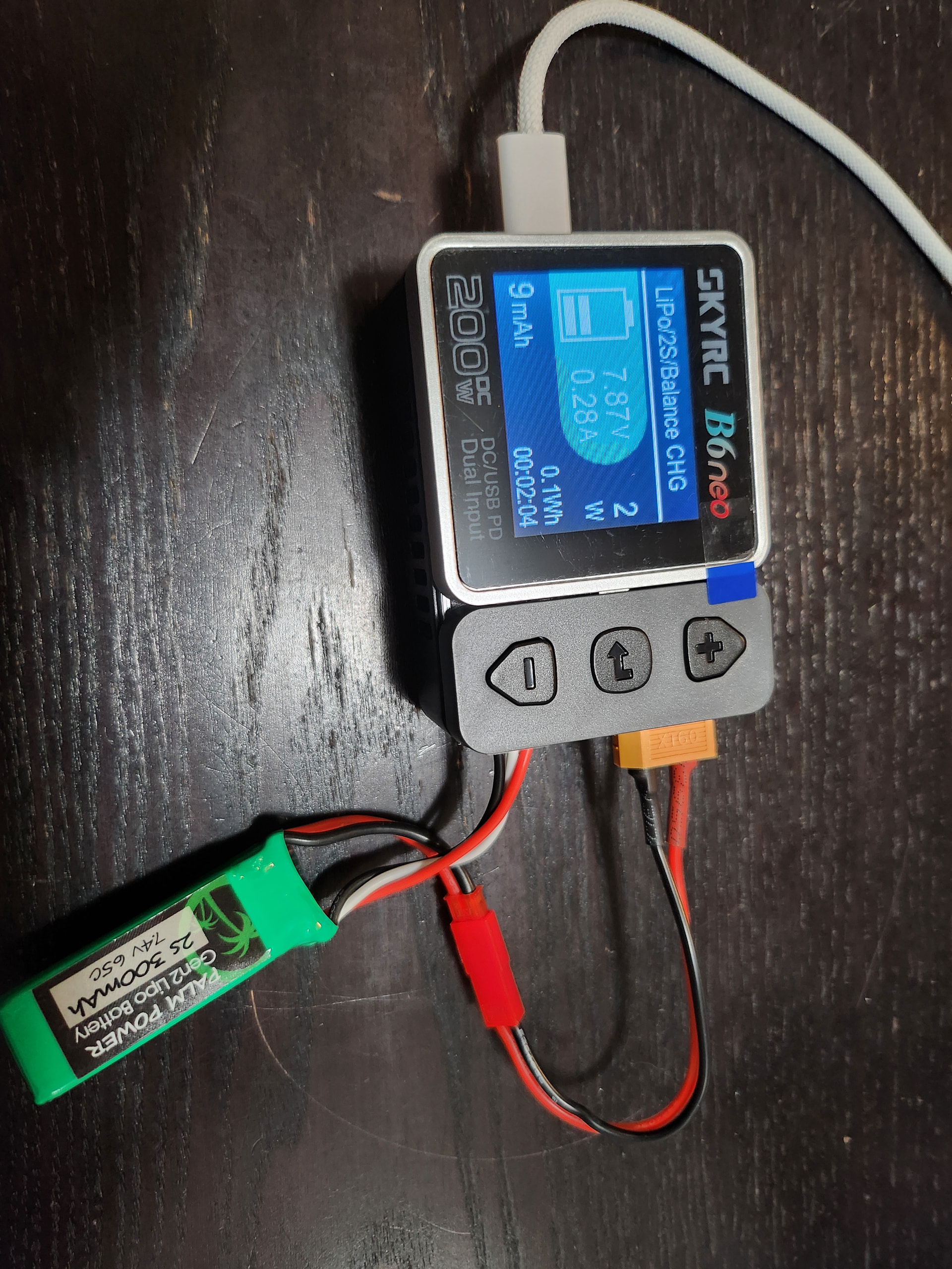
First step: charge the battery. There’s an 8 minute video about this charger.
Step 3 “servo” tells you to plug things into the receiver, but is a little unclear about which wires go where. Skip ahead to Step 5 and it explains the connections to the receiver in more detail.
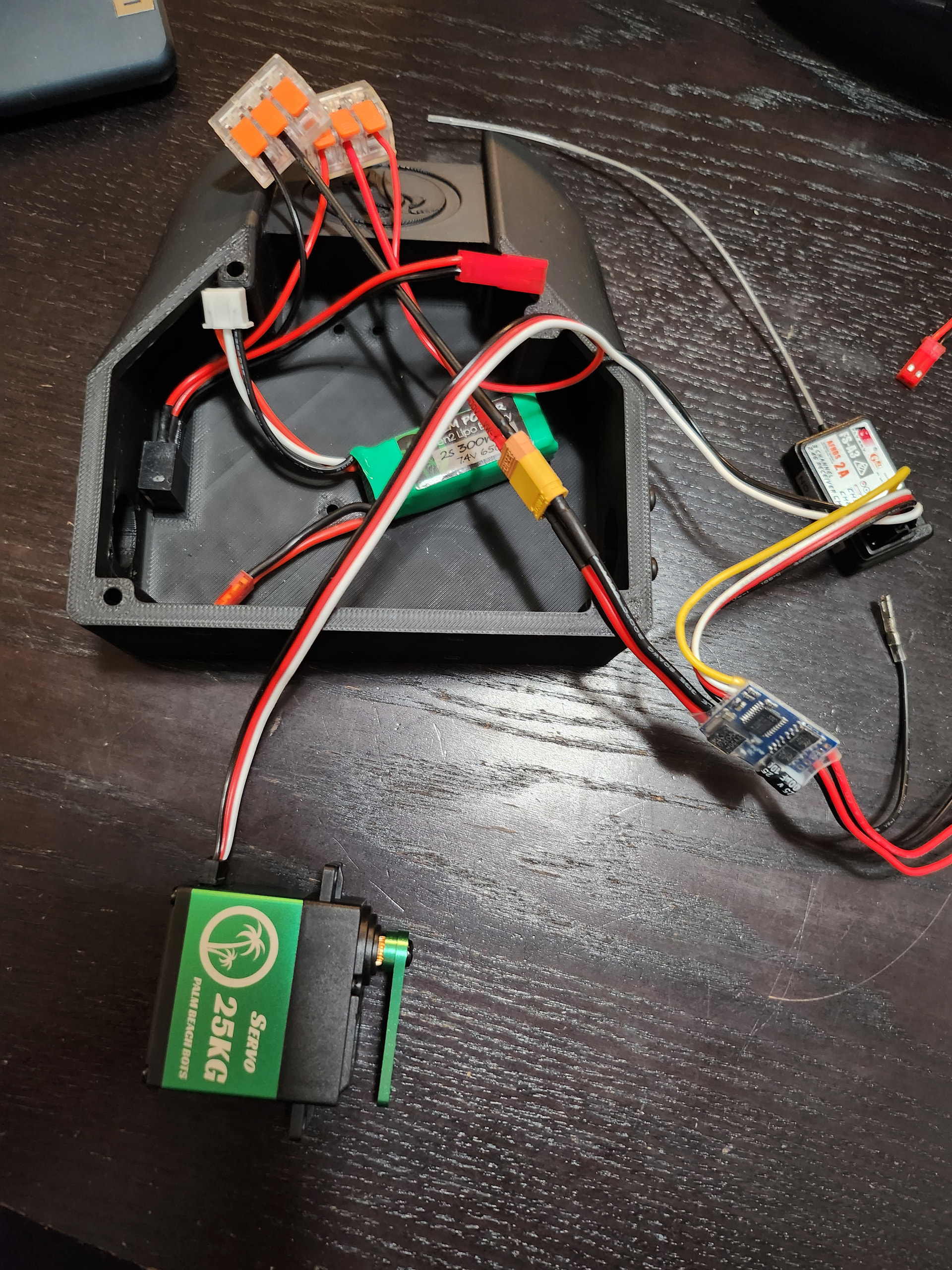
Neither the video or the written instructions is very clear about the wires going into the lever clamps.
The red wires are:
- 1 from the charge jack that you attached to the chassis
- 1 from the connector that attaches to the ESC
- 1 from the servo
The black wires are:
- 1 from the charge jack
- 1 from the connector that attaches to the ESC
The 2 black and 2 red wires on the other side of the ESC are for the motors
I had a bad moment when I turned everything on and the servo didn’t move… I unplugged everything and replugged it and it worked after that.
Servo mounts: Screw the screws into the holes on the short side of the mount ONLY A LITTLE, then slide the screws into the gaps on the plastic tabs (screw head on one side of the plastic tab, mount on the other), then tighten them down.
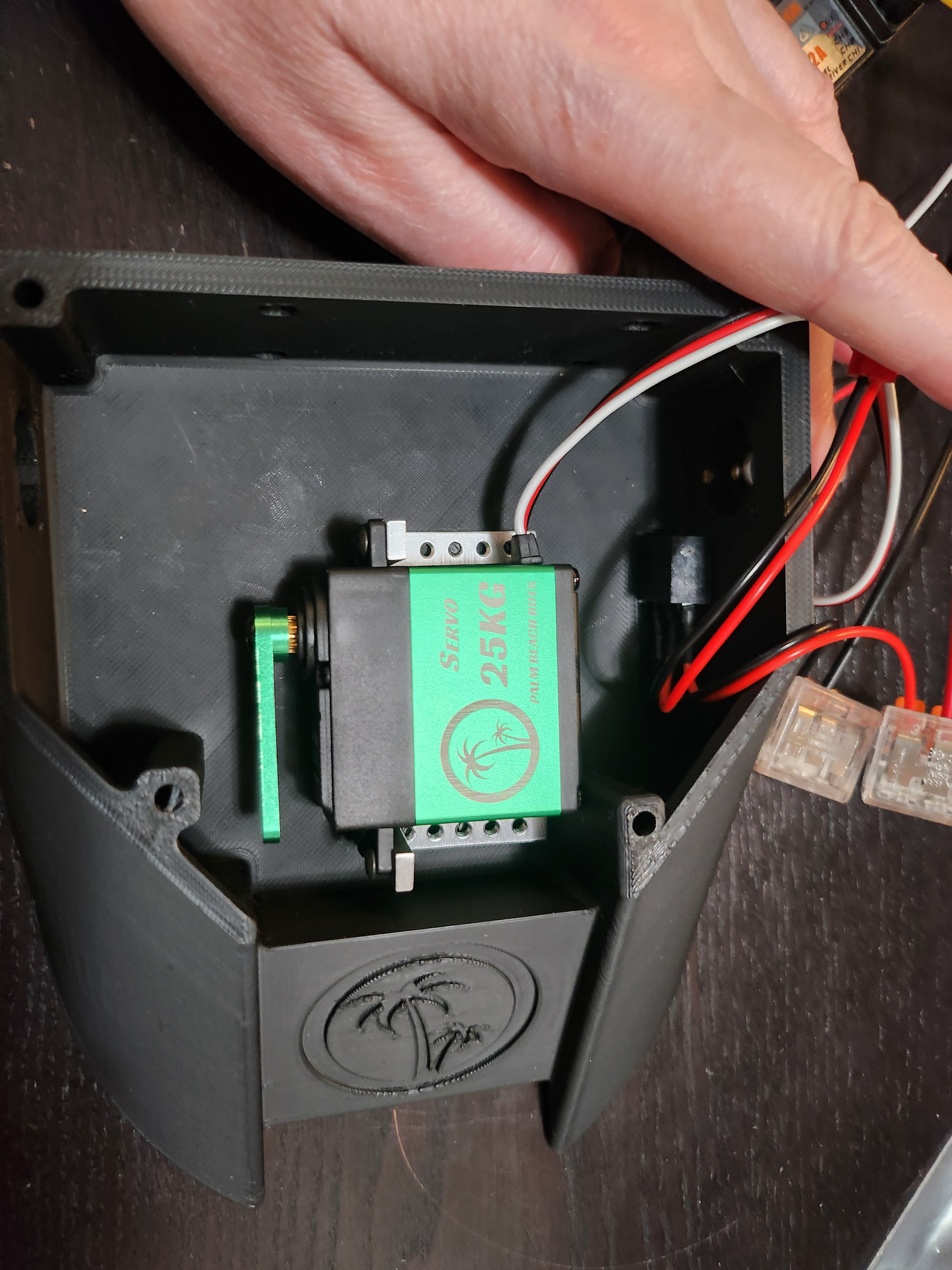
Mounting the servo to the chassis was really tricky - I didn’t notice that my screws weren’t screwed into the mount on one side until after I started hooking up the motors. It took a little while to fix it.
The instructions suggest tying down the wires before installing the motors. I couldn’t find zipties in the kit, but also it’s hard to arrange everything in the chassis to leave room for the motors, so I suggest doing the motors first to make sure you have space.
Be careful attaching the wires to the motors, it’s easy to bend/break the tabs.
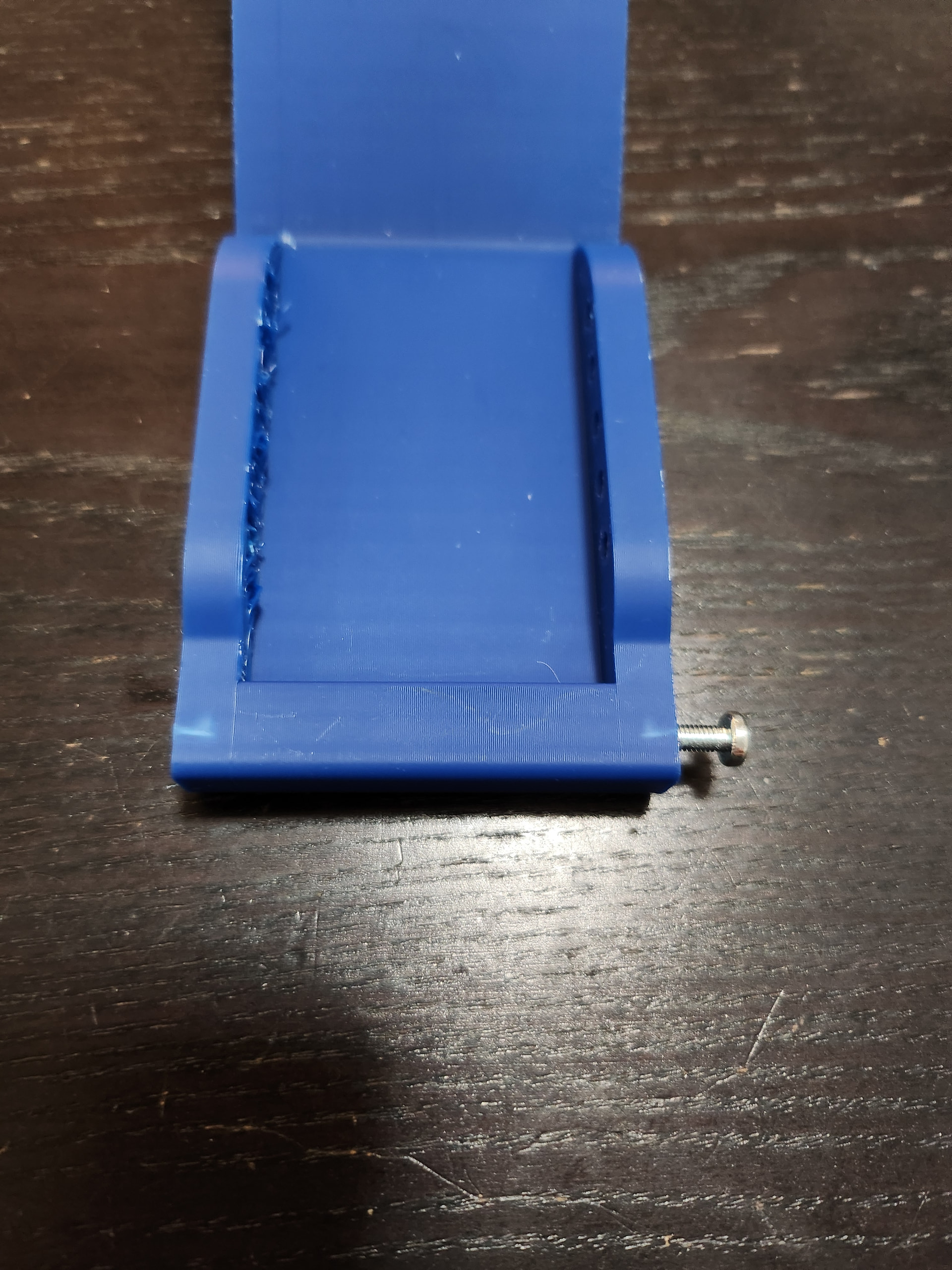
Step 7: “the holes in the scoop are undersized for a tight fit” ← understatement of the year. I couldn’t get the screw to go in at all until I reamed the hole out a little with a bigger screw. When I did start forcing it in, I got a discoloration in the plastic which made me think the plastic was going to crack.
So, I went to the store and got a pack of M3 screws to replace the 6-32s they specified. The plastic still discolored a little, but not as badly, and nothing has cracked. So, win.
I strongly suggest you test the motors and servo before attaching the lid. I had some loose wires that the servo was pulling on, so I ended up using electrical tape to make the wires and the receiver more secure.
I also tried the lid + lifter on the bot, and ended up pushing some more things around (and applying more tape) to make sure the lifter can move freely. It still doesn’t quite close completely ![]()
I had trouble with the included hex key on the screw for the lifter arm, for some reason. Luckily my household is equipped with precision hex keys which did work ![]()
It got a little awkward trying to hold the bot while attaching the lid and the wheels, since it had things sticking out of all sides.
I used a small wrench for the screws that hold the lid on, which use lock nuts.
It’s alive! https://photos.app.goo.gl/1AmZai3639EBaMbb7