My Fusion 360 3D Modeling and Taig 3D CNC Machining Exercise

In the ongoing quest of furthering my limited 3D modelling and CNC machining skillz I set myself the task of modelling and machining a small part.

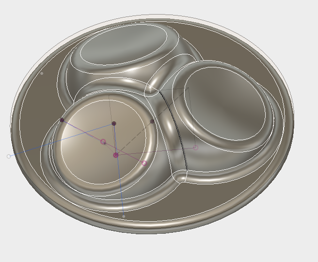
The fusion 360 model is essentially a single sphere cut in half with an angled slice cut out of the top part and then a small arc revolved inside the slice to create a dimple. This was then circular patterned around a center axis. Fillets applied to all the joins and then added an extruded circular base to finish this model off.

Then it was on to CAM machining paths. Being my first time at 3D machining this means deciphering what all the different 3D CAM path strategies do. I picked 3D Adaptive Clearing to rough away material, followed by a 3D Morphed Spiral for the 3 dimples, followed by a Spiral to clear out the rest of the material. Finally a 2D profile for the outer circle.

I was using a 1/16th Ball Nose end mill which required setting up a new tool in the Tool Library.

I’d love to say that this took me all of 1/2 hour but it was likely closer to 3-4 hours to do the model/CAM paths/Tools Setup.

Here’s the Fusion 360 model.

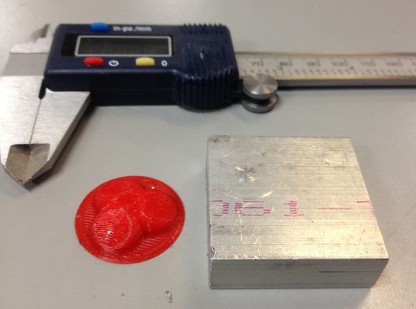
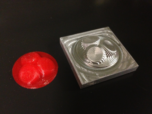
I 3D printed this model for a quick sanity check
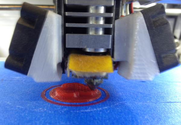
Looks good.

Using a 1 1/2" square by 1/2" thick aluminum bar stock for this.

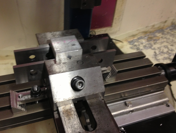
Aluminum stock all clamped up on parallels in the vise on the VHS Taig CNC.

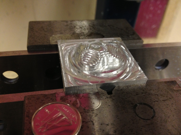
First up is the adaptive clearing:

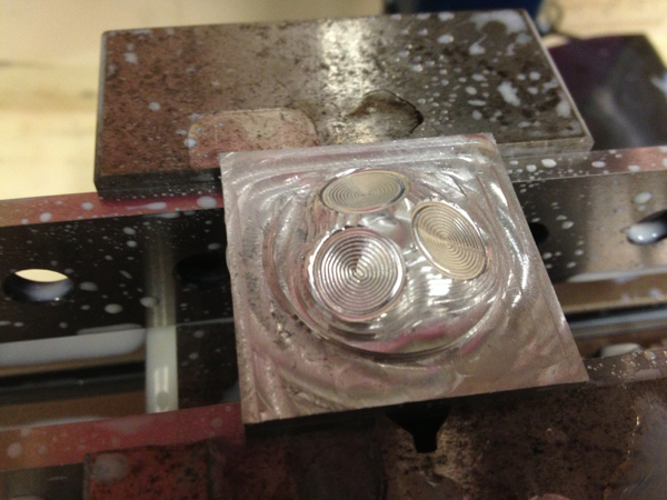
Followed by the Morphed Spiral to clear out the 3 dimples

Followed by the Spiral which clears out the rest of the material

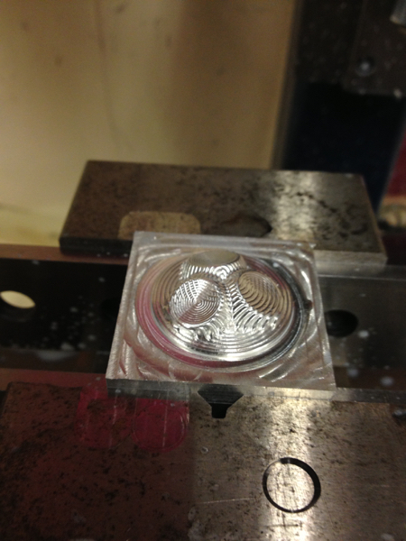
And finally a 2D Contour which just clears the material around the outside circle.

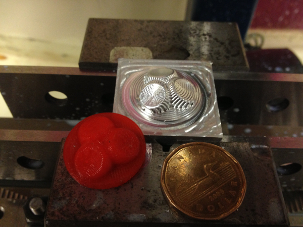
I have yet to figure out how to separate this machined part from the base. I was thinking of using the manual lathe but there is nothing to really hold with the chuck. Sanding is going to take a looong time. Sawing? I like my fingers thank you. Perhaps a different design then. Live and learn. :slight_smile:

What I would like to know is how to get those super smooth finish that you see on all the NY CNC videos. :slight_smile: I’m guessing a combination of CAM path strategies and different (Smaller) bits will do it. Suggestions and comments welcomed!

So the total time for this small project was about 8 hours. Learned a bunch. Hope to learn more!

Mark

4 Likes

Finer step overs in your cam toolpaths will get better surface finishes at
the expense of machining time. How big is the step that you machined in
with the 2D COntour? You may be able to make a split block of some soft
jaws to mill off the back of the part.

2 Likes

Thanks for the tips!

Step over was 0.02 and 0.035. I’ll play around with those.

How thick would the base need to be in order for soft jaws to have enough to grip on to? The base of this part is currently .035" thick. Design for manufacturability is obviously something I need to learn here too.

That may just be enough. You can just tickle the part so you don’t put too
much strain on the part.

1 Like

Hey Mark!
What I would do is redesign the part so that it incorporates the hold-downs
and some webs connecting the actual part to the hold-downs.
That way the toolpath will cut all the way through, but leave you enough
support structure to hold the part steady against the machining forces …
Then you’re just left to cut the webbing. Naturally you’ll want
some plywood underneath to protect the bed of the machine…

Also, no matter how how much you refine the toolpath, there will tooling artifacts
unless you buff them out. But that is a lot of work. If it’s an artistic piece,
you can experiment with different tooling strategies so that the tools marks
enhance or blend in with the shape of the piece and you can avoid having
to do any finishing altogether …

1 Like

That looks pretty neat in its own way, imo.

Adding on to what @Rob said, there’s an option in Fusion 360 to add tabs when you do a 2D contour. So you can do a 2D contour cut of the outline of the part, and fusion will leave tabs to hold the piece in place, which you can snip out and grind out later. For one offs, that’ll usually be quicker/easier than machining separate soft jaws.

Here’s a video I learned a lot from on 3D CAM - the guy reviews NYCCNC’s toolpaths so you get some sense of viable vs optimal toolpath strategies, and you can see some of the common problems and how he goes about addressing them with lesser used / more cryptic parameters.

3 Likes

Thanks for your suggestions @Rob and @ryanc!

I’m curious to know if you guys have made CNC’s anything? I’d love to hear about it.

Anyways I like the look of the tooling artifacts! I also want to see how “finished” I can make a part look.

I watched that “Fix Your $#!+” video a few days ago. It inspired me to do this part. Just watched it again at 75% speed which was made it much easier for me to follow along! :slight_smile: I keep learning something new every time I watch videos like this.

I used the vise for the first time on this project and did not really think about how I was going to remove this part from the stock. Tabs looks like the way to go for sure.

I want to try soft jaws at some point too.

Mark

I did a whole lot of mold cavities out of aluminum and machinable wax, back in the day for a mechanical idea that I wanted to patent. I had an oooold version of MasterCAM and a sherline mill with DC servos. I’m still learning Fusion 360 so probably not the best resource for that. But I did do a couple of really challenging parts that I had to machine from both sides, by flipping the part over and remounting it. Crazy complicated, but it worked.

Another idea is to drill and tap for mounting screws on the underside of the blank. It’s more work but guaranteed secure (unlike a vice) and you free up a lot of machinable surface. Just make sure to account for where the screw is going to be when the part is actually cut, otherwise the toolpath might intersect …

1 Like

Not sure about Fusion360 but in other CadCam software packages you can do what is called pencil machining, where you trace around the border of two different regions in 3d to sharpen details. You would use the smallest possible ball nosed cutter for this and it would be done last.

1 Like

Part looks beautiful, keep up the good work. Your dedication and persistence in exploring and experimenting with the taig is a huge benefit to the VHS.

The stepover of 0.02 is quite agressive for a finishing pass. There are limitations to the machine so it will be unlikely that you can achieve mirrored profile finishes but I like what you have done.

4 Likes

This topic was automatically closed 365 days after the last reply. New replies are no longer allowed.