Move over Las Vegas sphere, here comes THE CUBE!

Inspired by @packetbob documenting progress with Eddie, I figured I could share my journey of making a led Rubik’s cube from page to reality. I’ve always loved Rubik’s cubes, although up until about a year ago I was never committed enough to learning how to actually solve them so the one I had as a kid stayed untouched on display. After being sparked to actually learn more cube skills I figured that I should do some sort of led project that both would highlight my skills as a lighting programmer and designer, and be a fun one of addition to my growing collection.

So!

Opening up my journal I did some thinking, some sketching, and some late night rough measurements of what I wanted: a cube on a stand, where each face contained a 12x12 pixel matrix, with the idea being that I would control the ‘movement’ via simple button press; one button for each clockwise and counterclockwise clockwise of the 16 different possible actions.

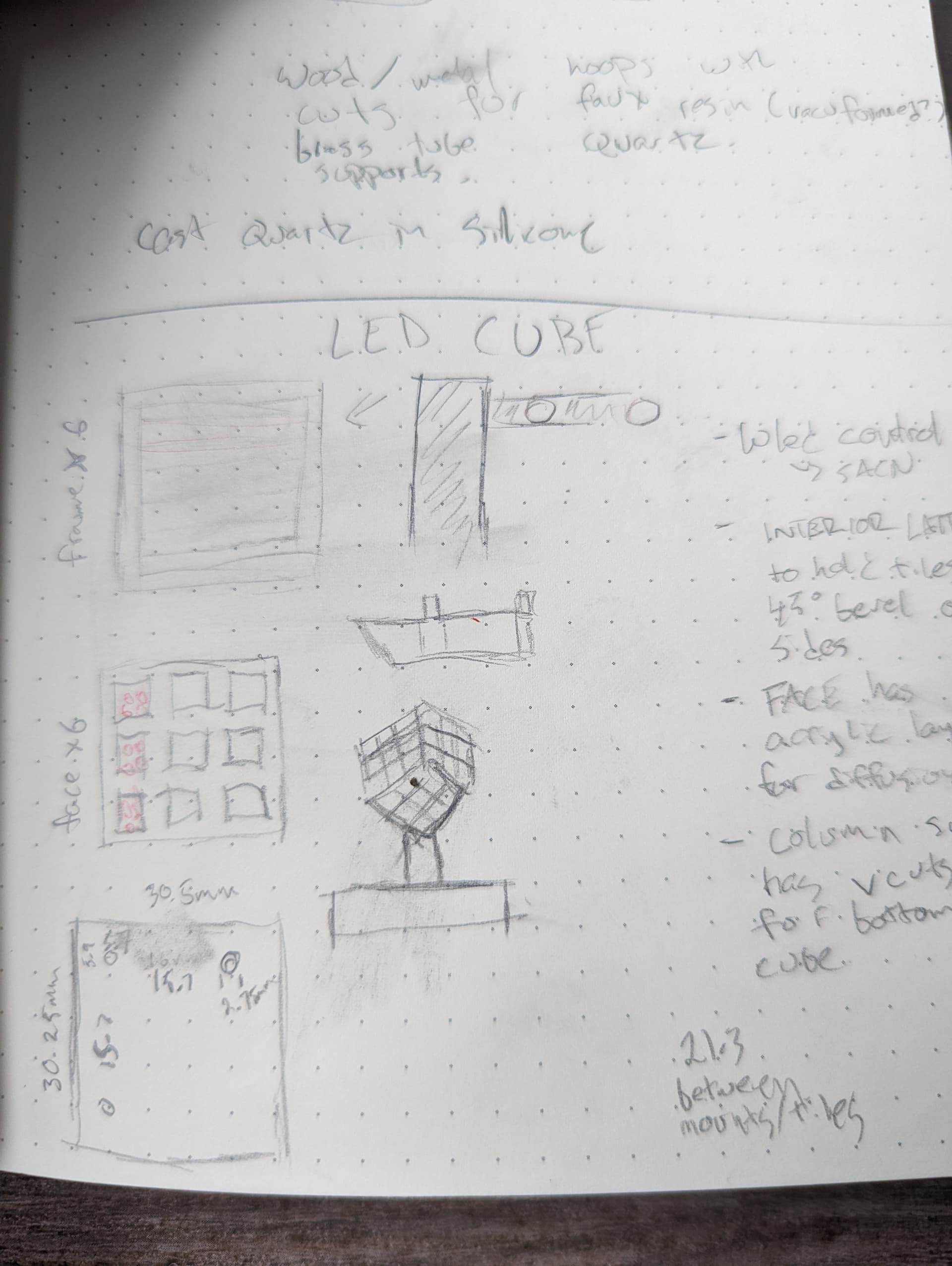
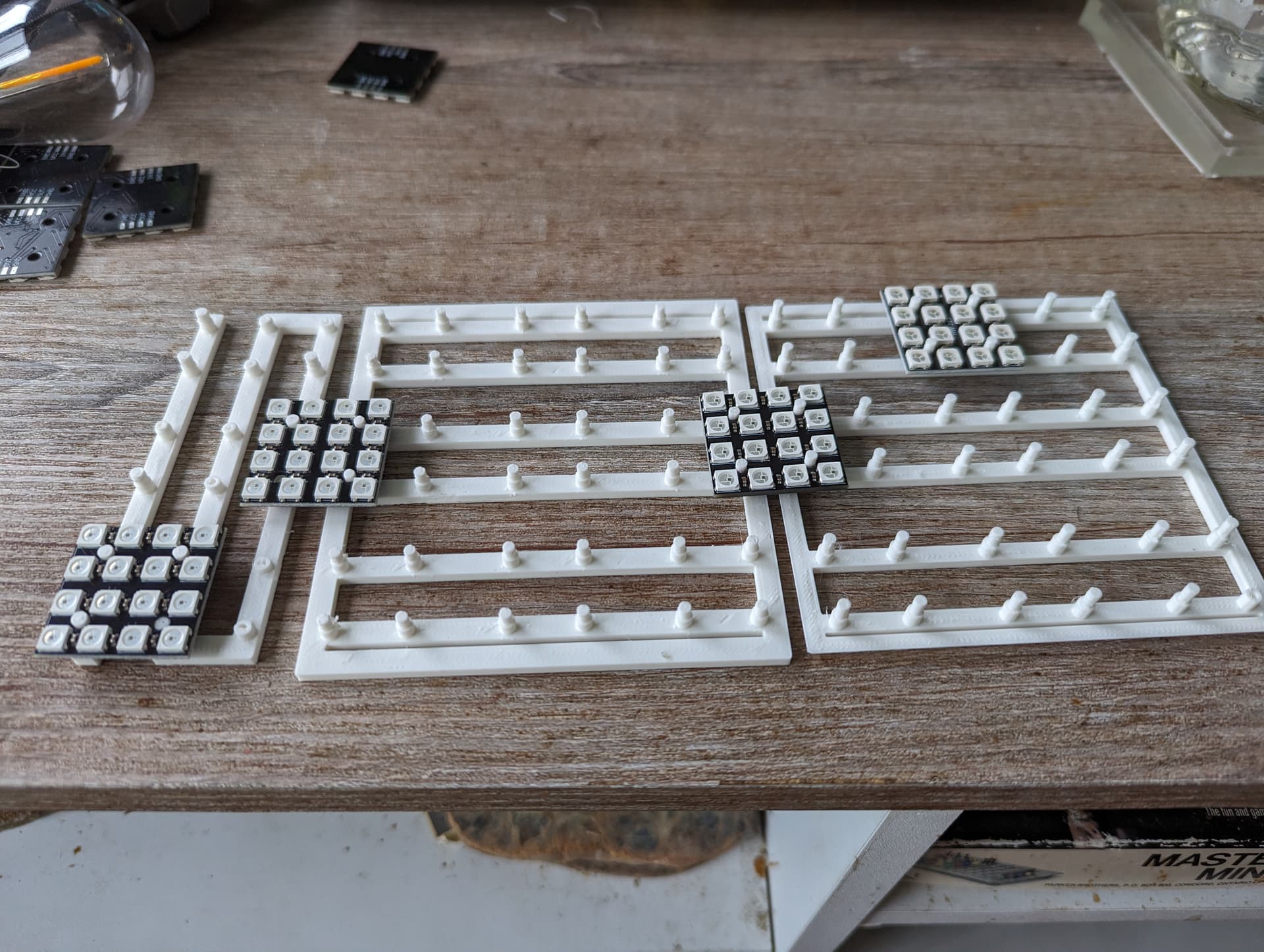
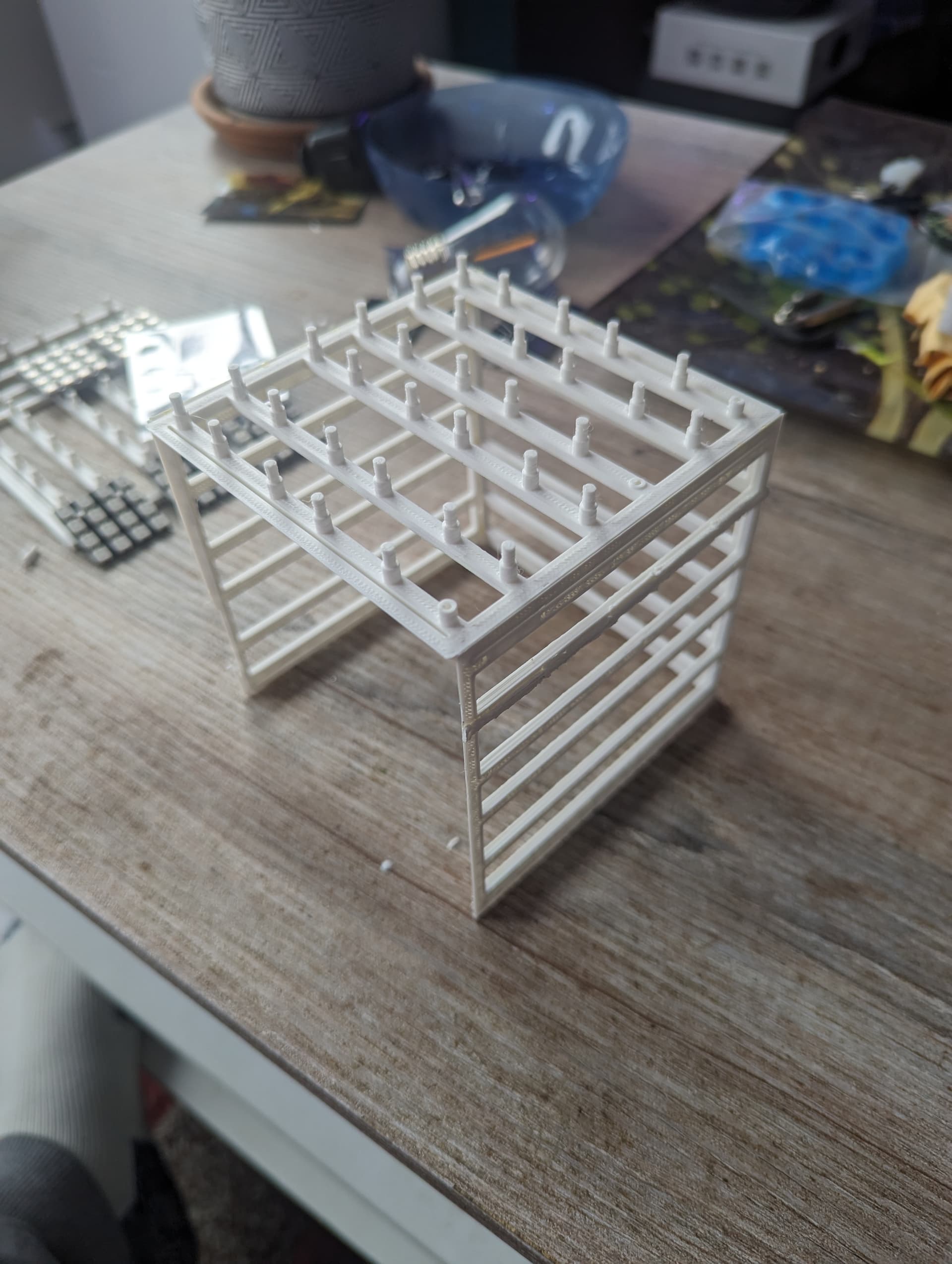
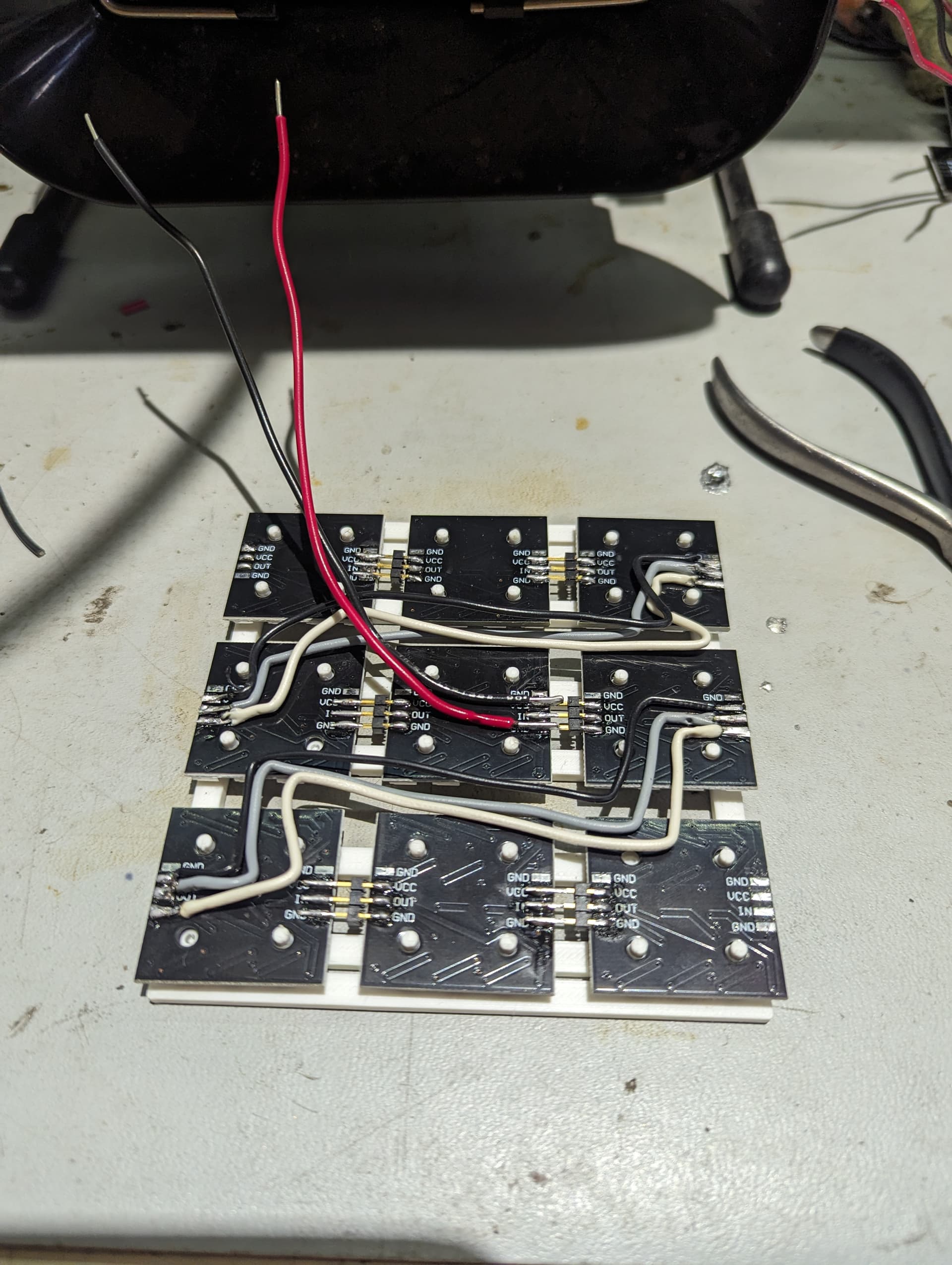
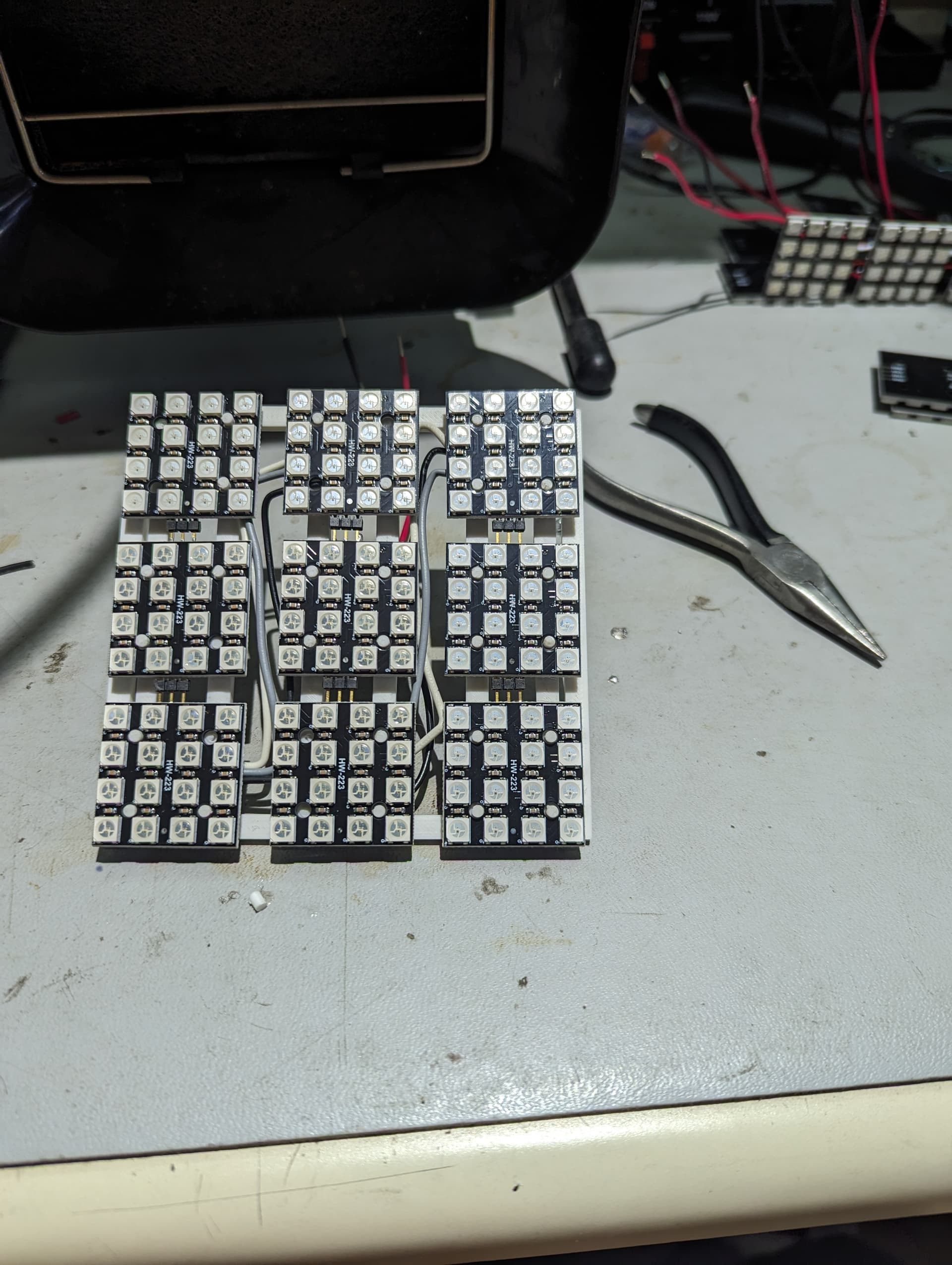
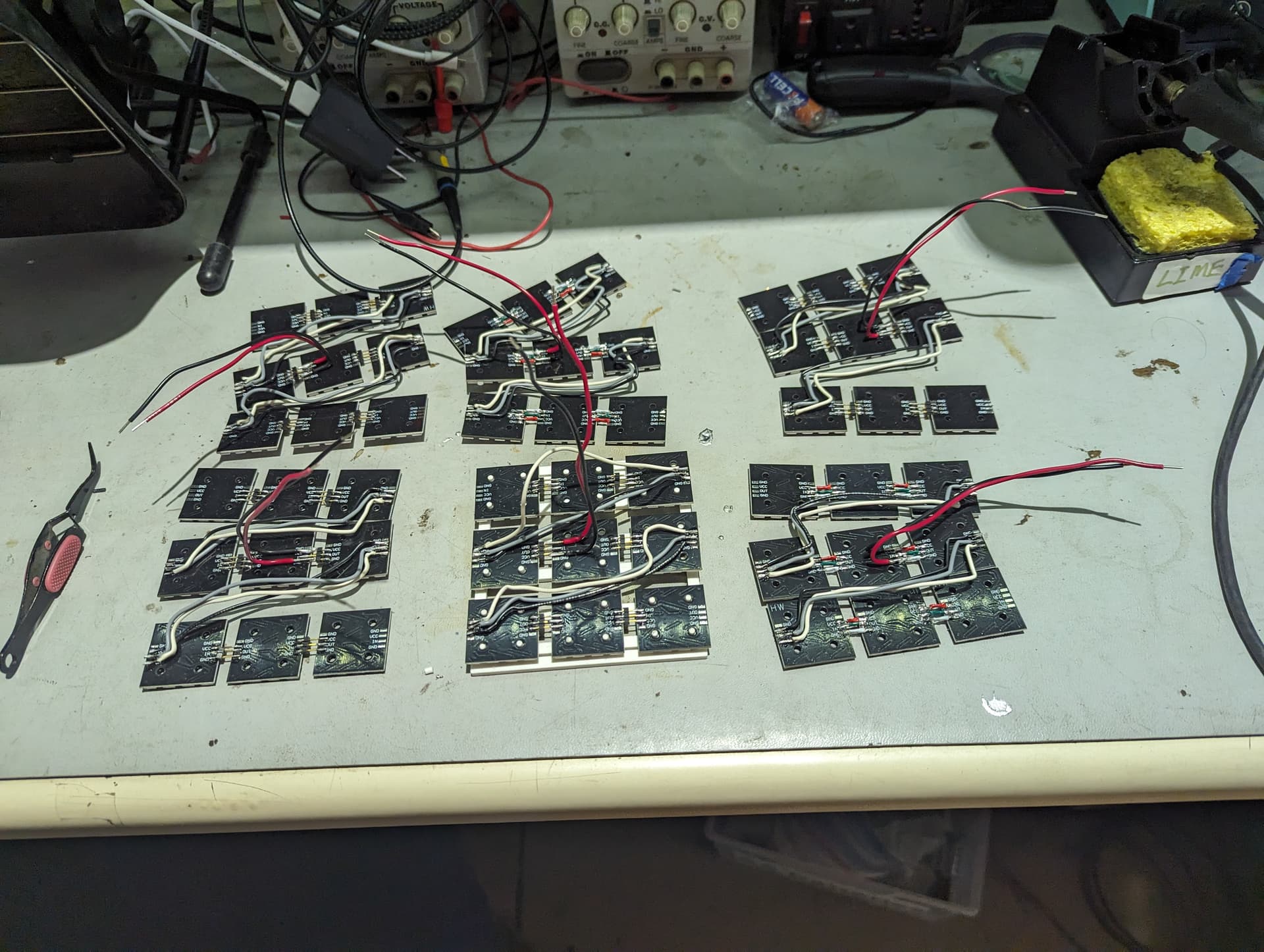
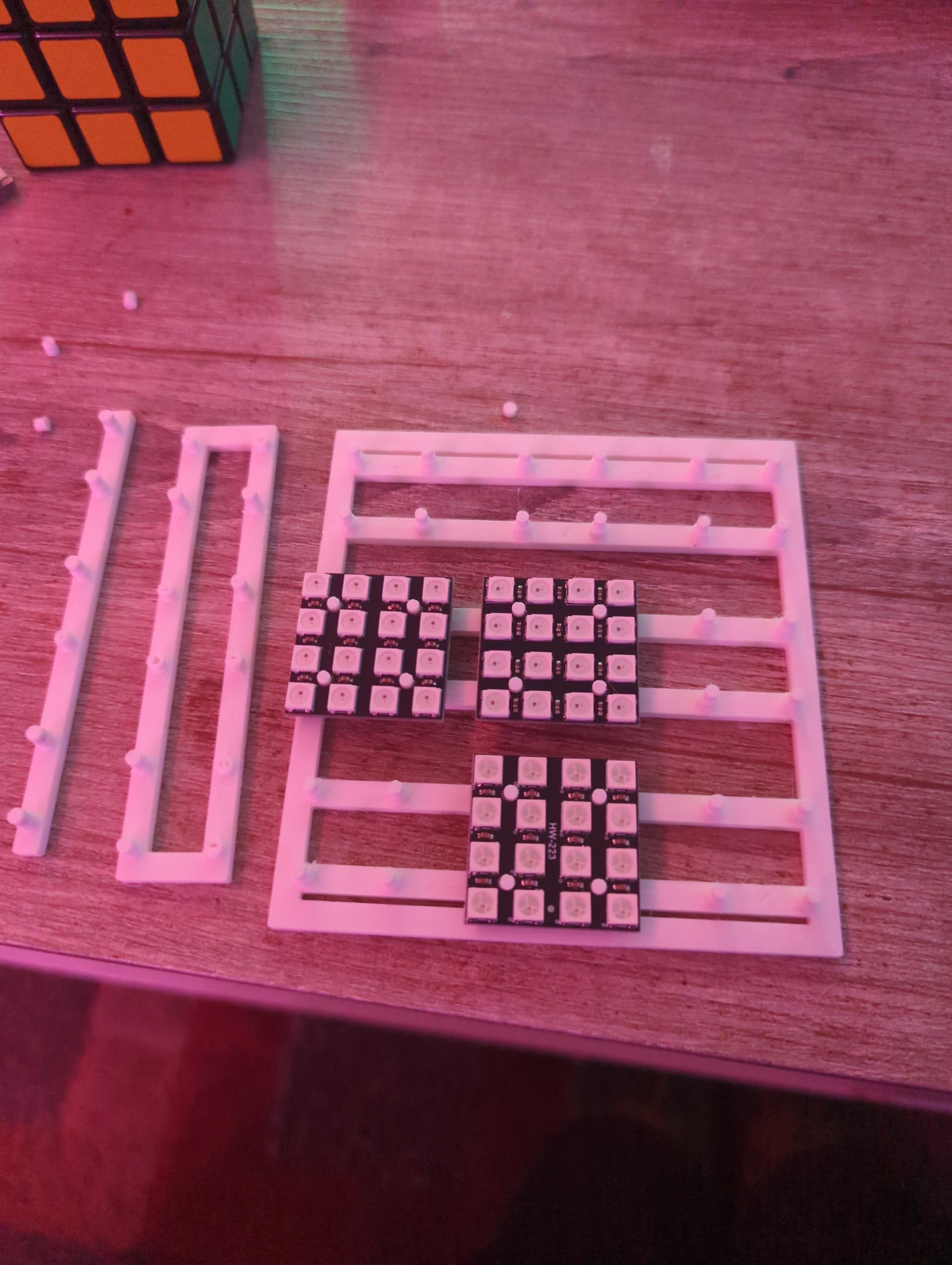
I decided that the best plan would be to have a grid of 4x4 ws2812 led tiles on each face, with a frosted acrylic panel to hide the components, and a faceplate grid to outline everything and sell the Rubik’s cube aesthetic.

Pleased with the idea, and some encouraging direction in jumping from printing other people’s models to creating my own from scratch I put on my comfiest maker coverings (a kigurami otter onesie), found a Spotify playlist for 'epically inspiring 80’s montage playlist, didn’t like it, put on my all rush mix tape instead, grabbed a 2l of Shasta and got to rocking!

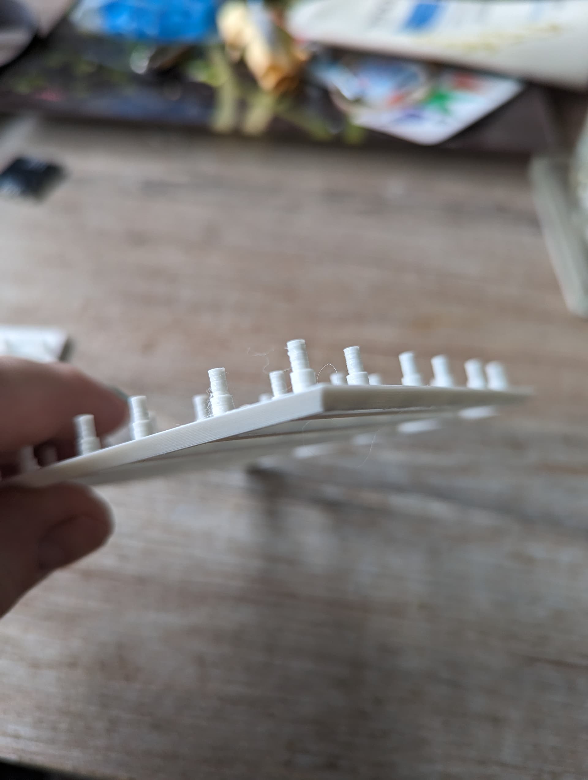
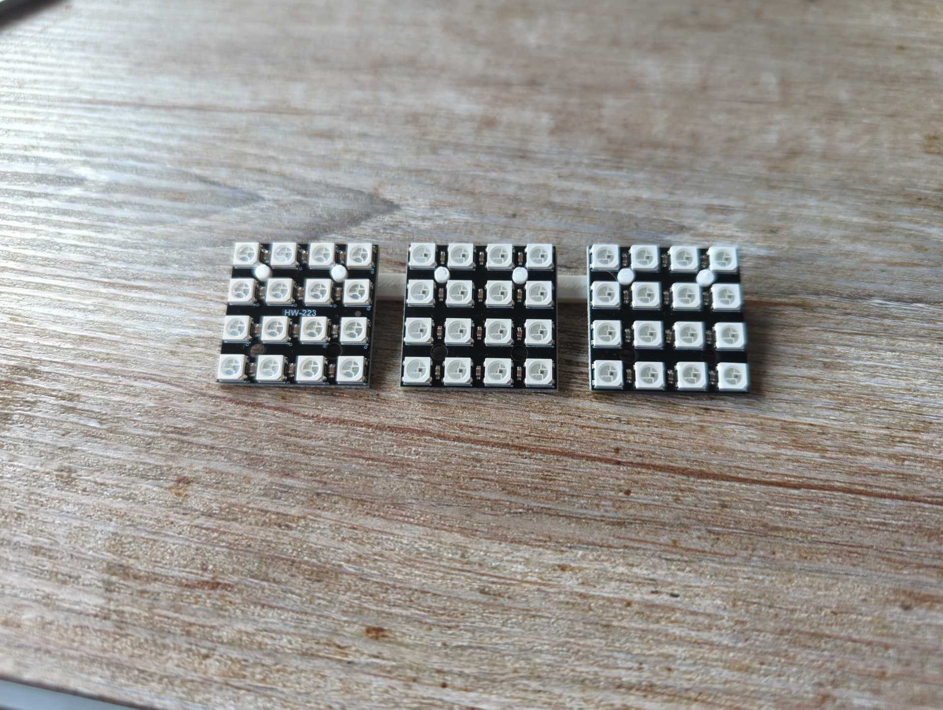
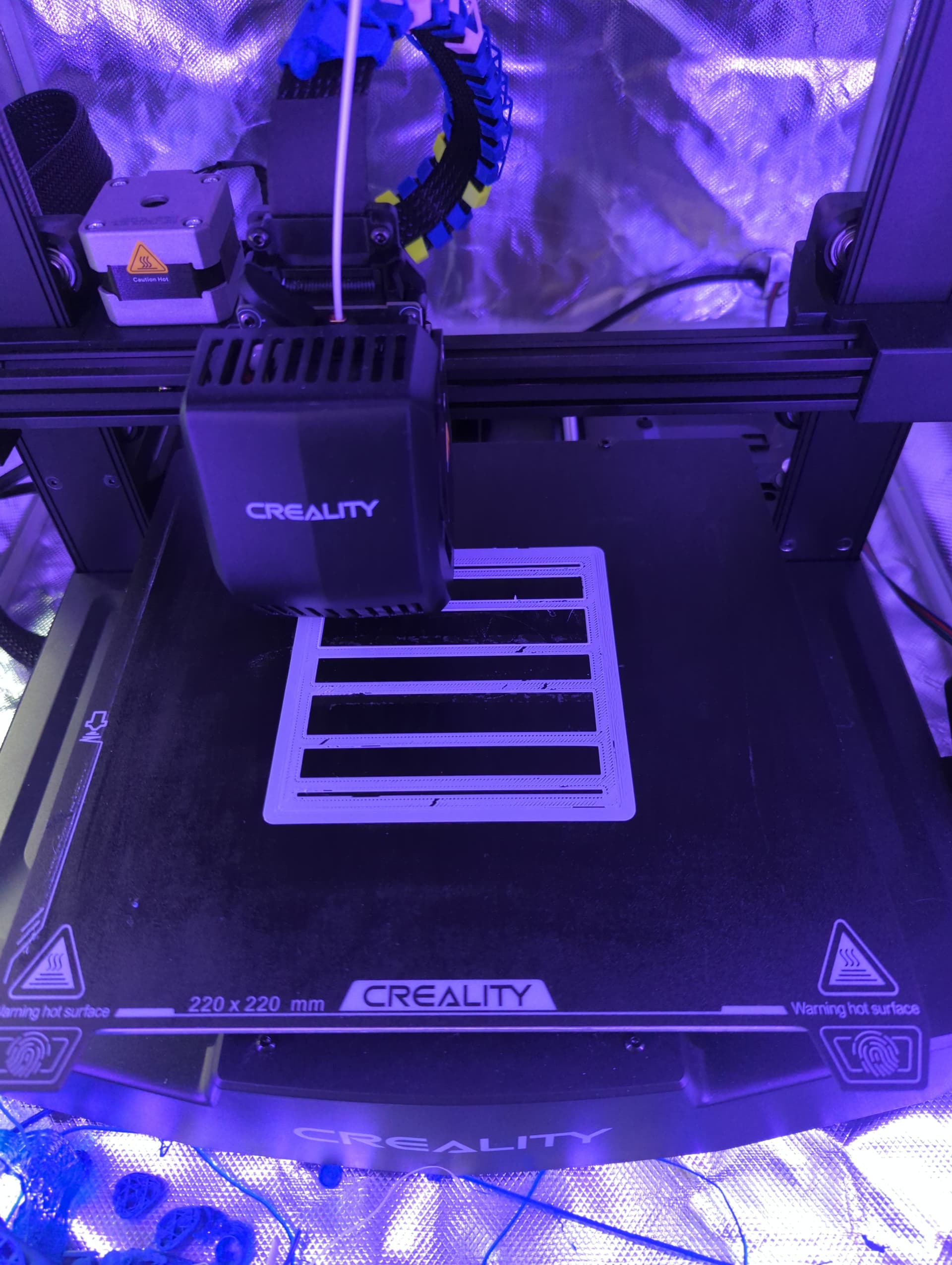
I first wanted to make sure that I was happy with the spacing between tiles, celebrating making a successful baby’s first 3d print in about 15 minutes that did exactly as expected.


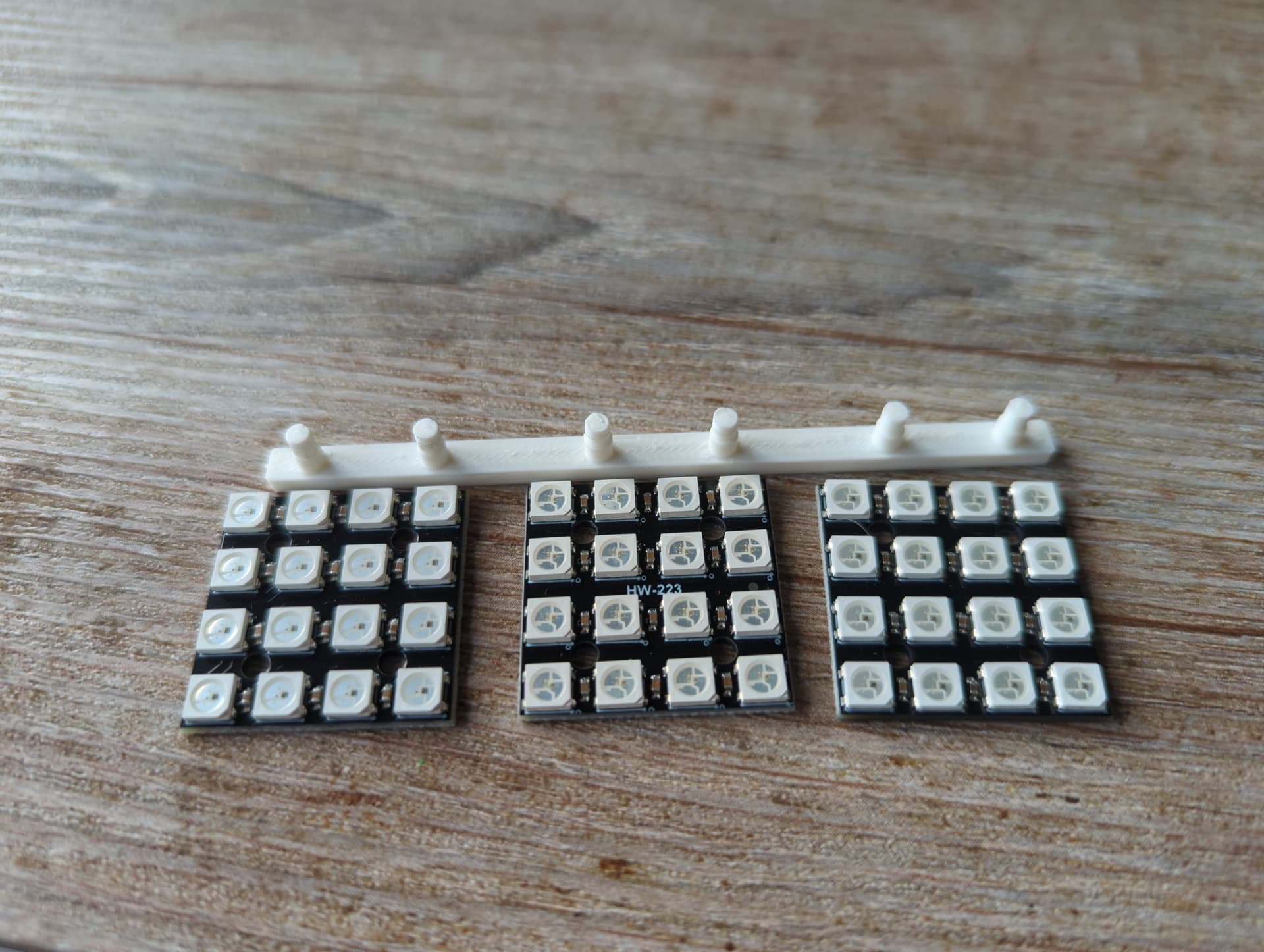
Surprised and encouraged by the accuracy I carried on and made myself a single row frame to make sure my measurements were correct on both axis. A flip of the cassette and a bit more zero cool cosplay and I had done it! A frame fit for a… Set of led tiles to rest comfortably on.


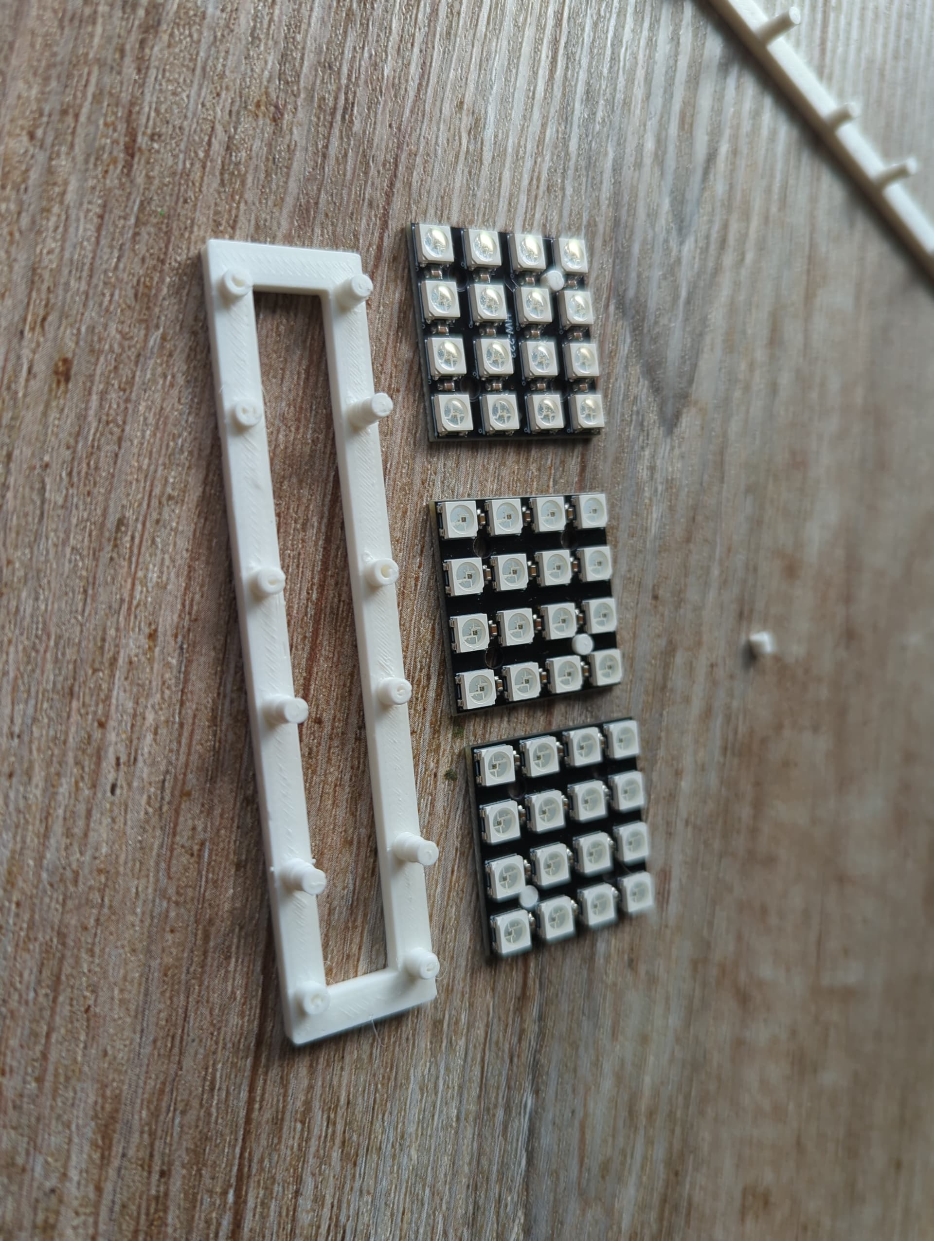
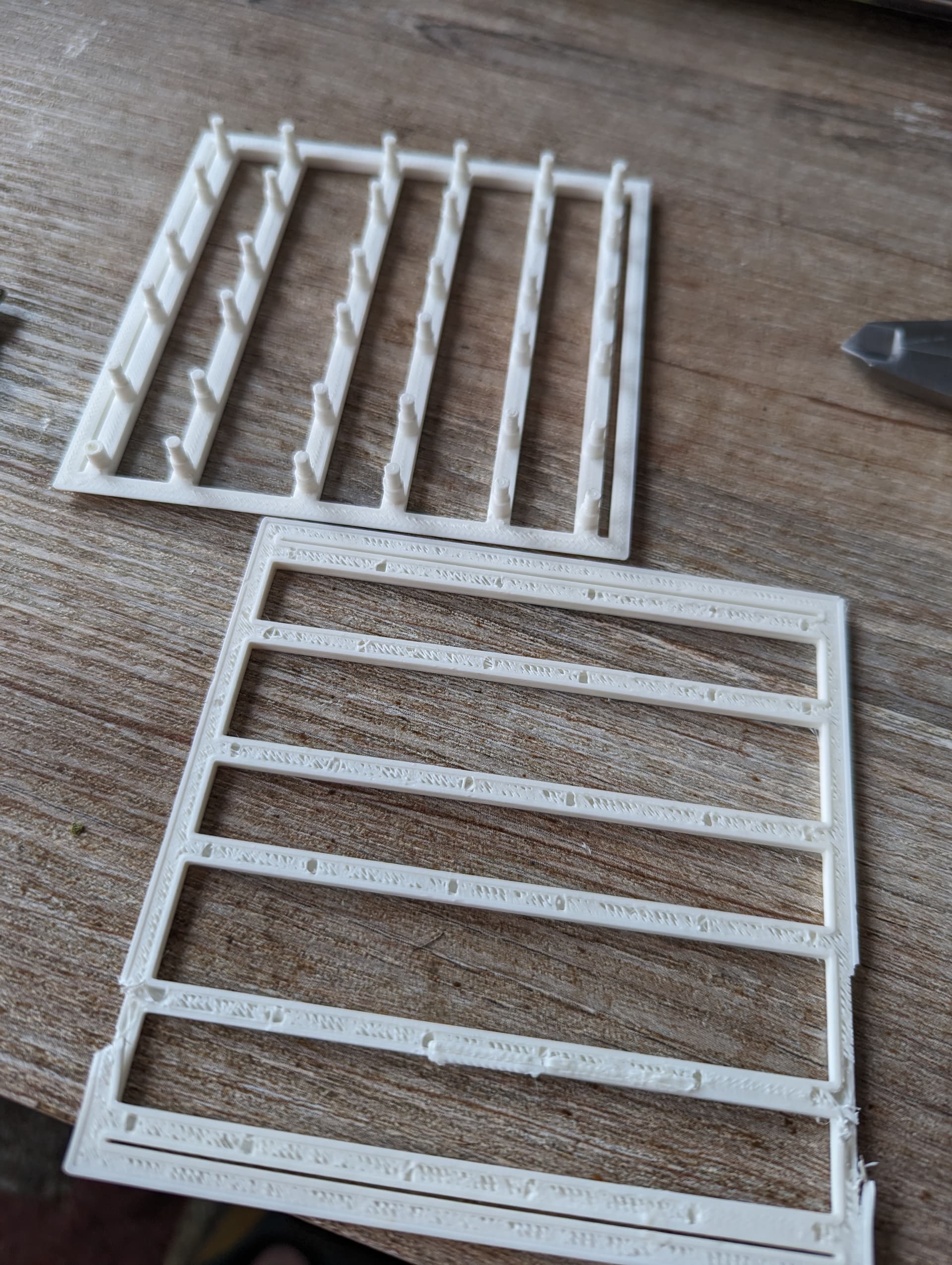
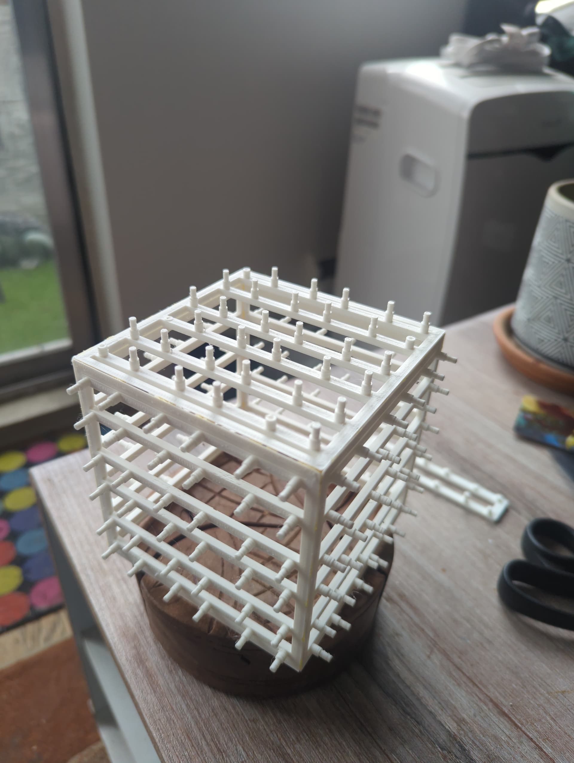
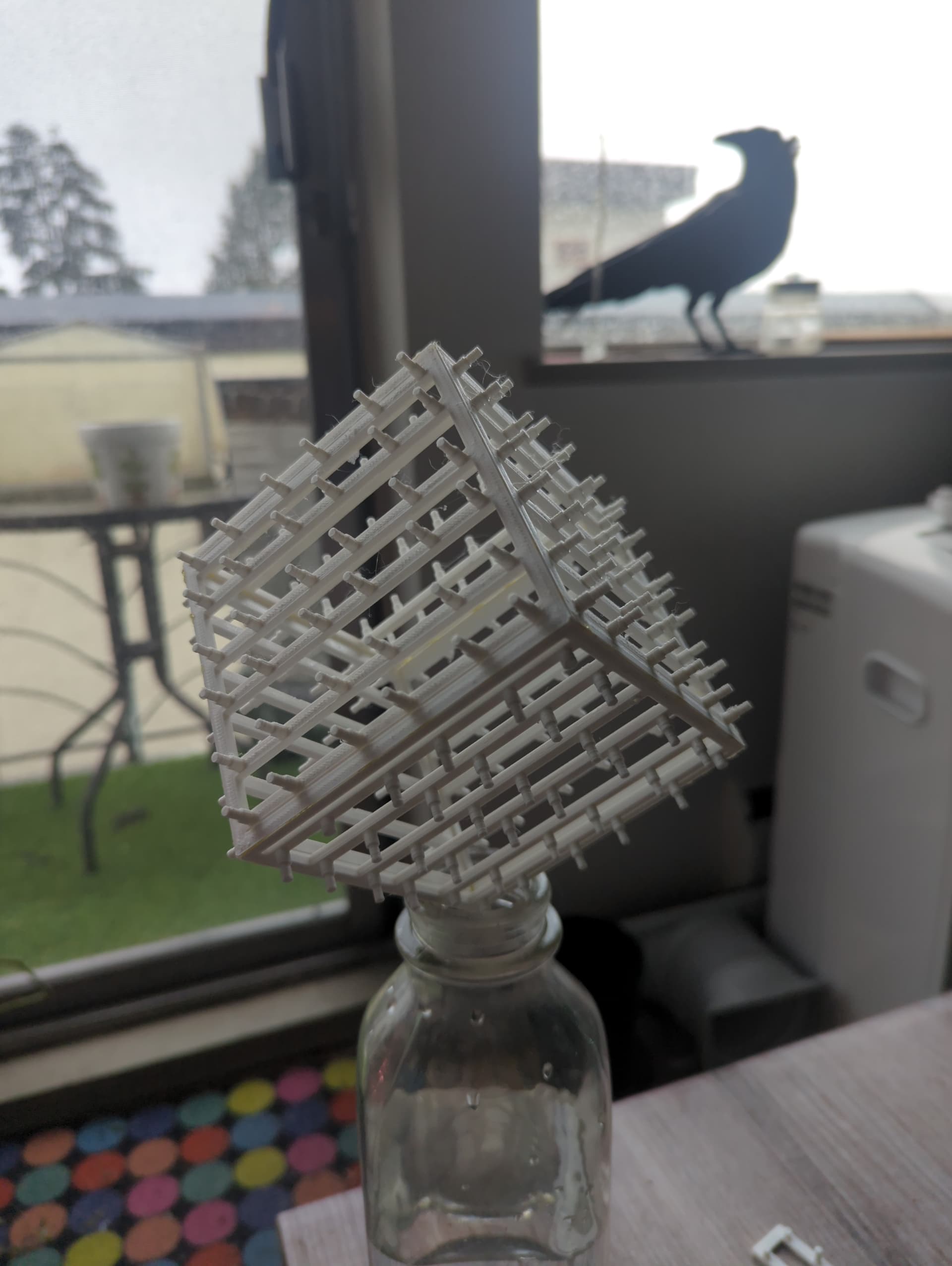
I used this time to ponder on the distance between the edge of the tiles and the edge of the frame for a moment and continued merrily down the rabbit hole of cad revisions and schematic improvements; tweaking this, and shifting that until I was peering at a Cura slice of something I was anticipating holding aloft like a Simba plush on my balcony. I lit a candle as offering to the makers maker, said a silent incantation to ward off the deamons of printing errors, and hit ‘confirm’.


KOOLADEMAN.GIF!

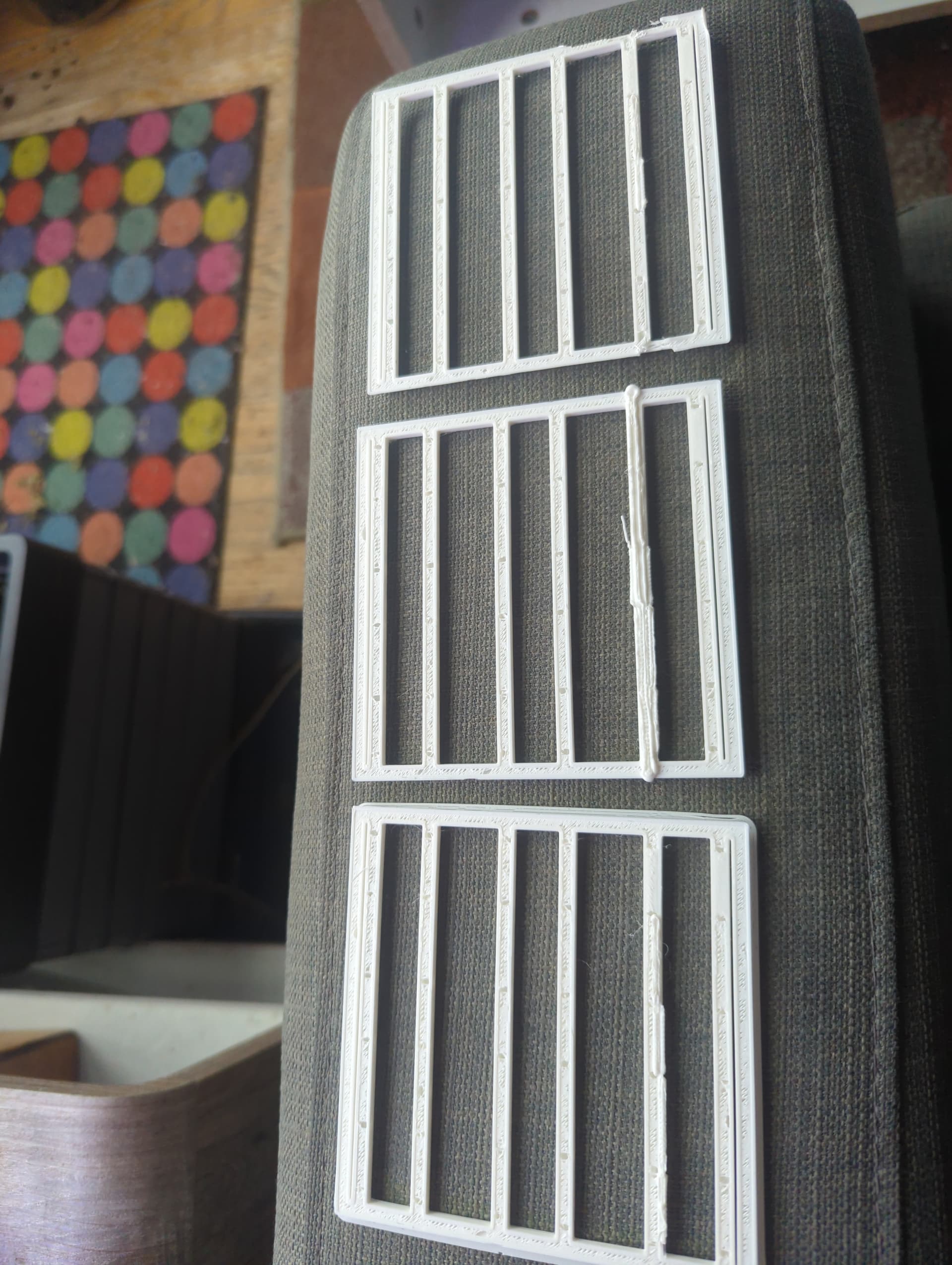
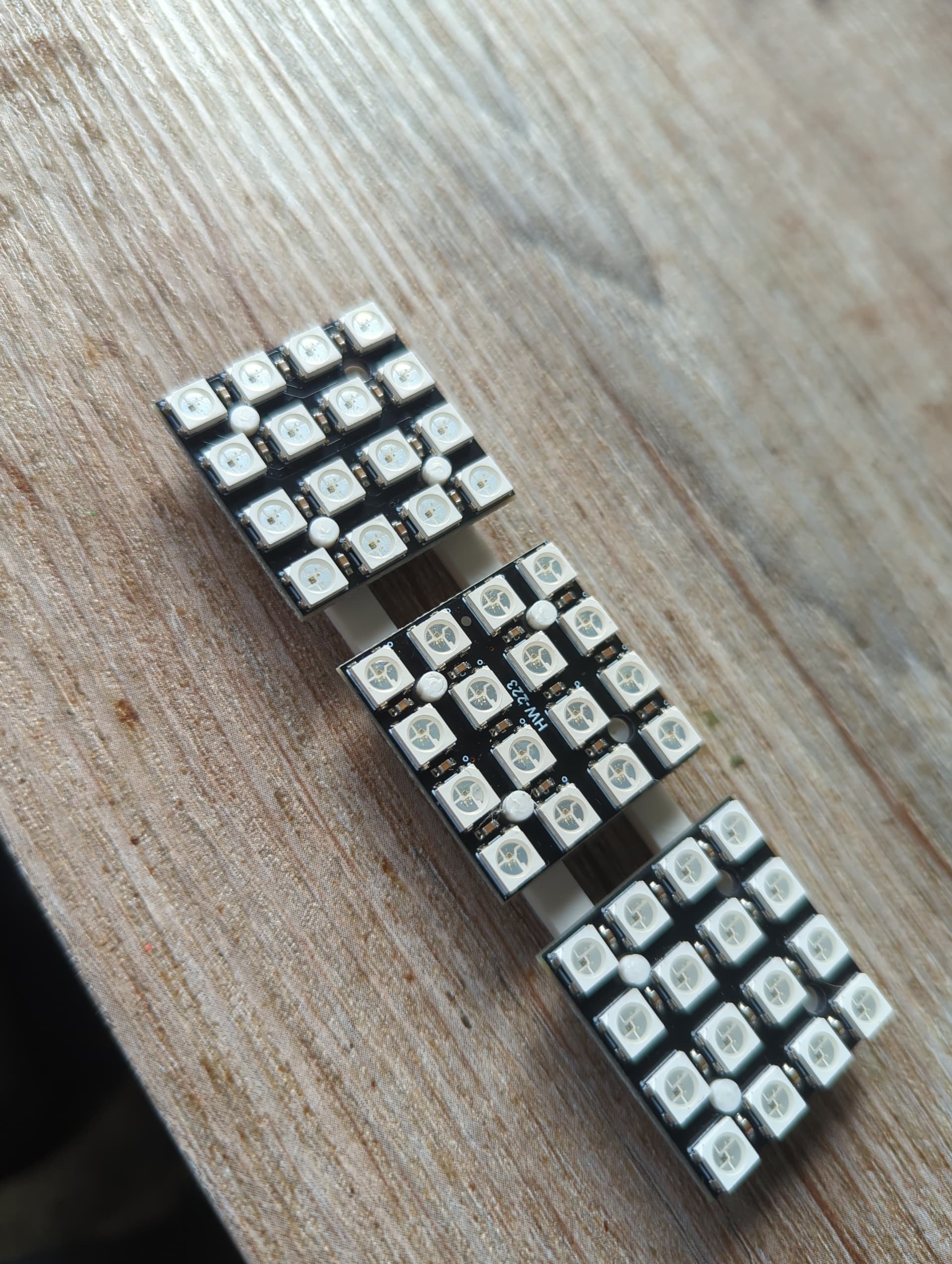
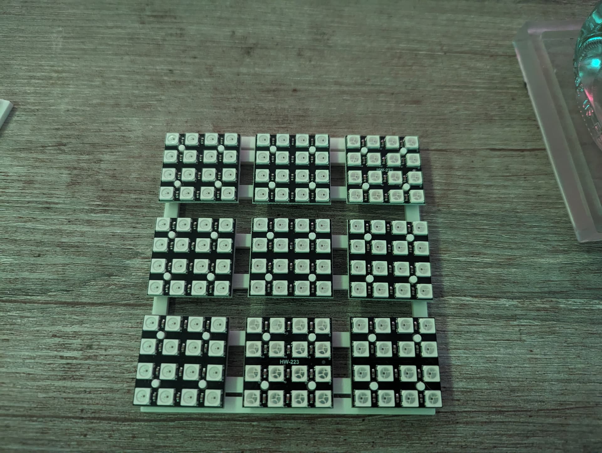
I felt like macho man Randy Savage snapping into a slim Jim! The test print was a complete success. I was happy with the spacing between tiles, the distance they were offset from the frame is perfect for the wiring to fit in, and the two distances used to offset the frame from the tile edge provided lots of useful information to sleep on

Next up I’ll be needing to bevel the bottom of the frame so I can fit 6 together without weird overlaps, change the frame dimensions slightly to reflect the edge distance, and begin thinking about how I want to attach the frame to the base while still allowing wire pathing and access for connections!

6 Likes

I hope you don’t mind me bikeshedding in here:

You could have a “timed challenge” mode where the squares gradually flip colours, and you have to solve it before the setup has changed. Every successful solve makes the timer get shorter

It’s a great idea, I’m not sure how… Feasible it is considering the constraints of a physical Rubik’s cube. Because the cublettes are constant and ‘need’ to be paired in a specific way (ie: blue is across from green, so you couldn’t have a blue/green edge together AND you can’t flip the edge around), combined with how the algorithms chain, it may quickly make a solve impossible by sheer chance! Although I will agree that having a set mode which just throws colours onto the faces regardless of accuracy would make for some nice patterns…

Even though there are over 43 QUINTILLION (one followed by 14 zeros) on a Rubik’s cube already, and it would take over a trillion years to view all of them at a 1 second interval!

Great progress! Looking forward to seeing the next update :slight_smile:

Annoyingly, I’ve been having to put the cube on hold for the past few days for something called ‘wrok’ I think. It’s caused a bit of a setback and delays in print testing. I spent a few attempts at beveling the sides of my model, so I could get a flush fit when assembling of the frame and printed off a part.

There was a success in the angle and size, however I noticed that I mis aligned two rows of posts. Not a big deal, with a few tweaks another print was started and I began to see some pleasing results

Unfortunately, something has changed. My latest model file seems to fail on layer 13, an ominous portent of troubles on the horizon, or just forgetting to triangulate the model before slicing? Only another test print would answer these questions!

After two more failed prints on the pile I have had to again return to the theatre mines to produce more entertainment for a while, but not before beginning to assemble a mocked up frame. Why fret over failures when they can still provide useful information for future prints!?

My next steps as suggested by #3dprinring is to try a print with a rotated orientation, as well as try a different SD card, and remake the model with the revisions I’ve decided on!

3 Likes

After taking a bit of time to do more of this odd ‘work’ time wasting activity, I was able to make more progress on this beast of a cube. I seem to have embarked on a life lesson of time estimates and workflow modifications.

I finished printing my frame prototype in PLA and feel very pleased at how my model making skills have progressed. The frames all line up fantastically with each other, and I am able to place it in the position I am wanting


I moved into the space for a bit of soldering fun, to realize my first overlooked aspect of this part of my build… Connecting all the tiles together required me to cut and strip tiny bits of wire. Sooooo, I found a comfy chair, threw on the latest podcast of my brother, my brother, and me and began 2 hours of stripping and cutting.


Yup, I managed to get thru all the wires I needed, and after a bit of over heated melting, I managed to connect 6 sets of tiles together. My eyes and brain informed me I needed to rest for a while, so I set things aside for a few more days. Upon lamenting of my wore struggle, @packetbob pointed out I should just use bare wire instead since there is no chance of shorting connections. Filled with newly minted confidence, I returned to battle, resolving to push as far as I could with connections. I found some jumper pins and got to work


Suddenly all the tile sets had been joined! With glee I moved on to connecting power leads to 6 sets of tiles, and then… Tied all the sets together into their face groupings! Huzzah! The progress continues, with the next steps being testing each face with power and data, linking the data lines together, build the controller, print out the final frames in PETG and then assembly!!!


Weeee!

7 Likes

An exciting tiny little update:

Papa Bezos left for me a power supply and a few other goodies, so I figured it would be a good time to come in and try my hands at some wire routing!

I got in and did some laying out of parts, to try and figure out the best way to organize the final configuration, as well as what would make for the simplest wire pathing. A few attempts later and the above placement was internally agreed upon. I channeled my inner packetbob and spent the next couple hours bending, cutting, crimping and screwing down wires. When the haze of work finally cleared I had something that was pleasing to at least my eye, and ready to get some panels tested and going.

Alas, I wasn’t monitoring my time and in my working flow state I came upon my cut off time. Other tasks need my attention, my fridge needs filling, and my house deserves a good cleaning!

Next up is testing the wiring and data paths with the esp32 controller, and then the process of actual assembly begins!

6 Likes

I can’t, and yet can believe it’s been a month since I last updated things regarding the CUBE (yes, it seems to be so imposing and impressive that it needs to be all caps) that I figured it was time for a little post.

Turns out that it feels really hilarious to know that the reason an led supplier has to remove an item from their webpage is specifically me. Basically once I realized that I was going to need new spares, I reached out to the company that fulfilled my original Amazon order and asked if I could make a big ol’ bulk purchase of led tiles. The reply I got was both encouraging and giggle inducing: ‘we absolutely can help you, but you are asking for about 4 time the stock we normally have on hand.’ turns out that lead time is about 3 weeks with an extra week of shipping time. So, as of writing, the CUBE is in a holding pattern until I receive the order.

In the meantime, I shifted my focus towards another project I’ve been chipping away at; a faux neon led unicorn desk clock. The idea is to have a base that looks like a cube of ‘magical meadow’ has been extracted from the ground, with 4 clusters of quartz surrounding a kitchie rainbow cycling unicorn head. Some learning stumbles and a few hours of rewiring later the hard part is basically done!

Behold! A led unicorn!

There are still a few things left to do; from fixing the diodes to the quartz crystal chunks, to adding a layer of dirt to the base, and covering the white cylinder on the bottom of the unicorn. Soon however, it will be a nice and happy complete piece, and then it’s back to the CUBE!

4 Likes