I designed a mechanical iris using Autodesk Fusion 360 then 3D printed it using the Tinkerine. Tweaked version available here: Mechanical Iris by JDMc - Thingiverse

This model was intended to be a proof of concept and test to see whether the slot mechanism and tolerances would work for a more complex version. The video has generated a little interest, so I am going to document the process so far.
Background
I’ve made a few iris mechanisms in the past: a 3 blade iris business card several months ago, and a lasercut version out of cardboard. Both of them were designed by others and I simply used their plans.
Design
I had a look at various iris and aperture designs. Iris mechanisms, where the blades meet in the middle, all seemed to have 5 blades. Apertures, on the other hand, tended to have more blades( typically >9), but the blades have to overlap. I decided to focus on the iris type and see what factors influenced the number of blades.
I created a sketch in Fusion to get a better idea of the geometry and necessary constraints.
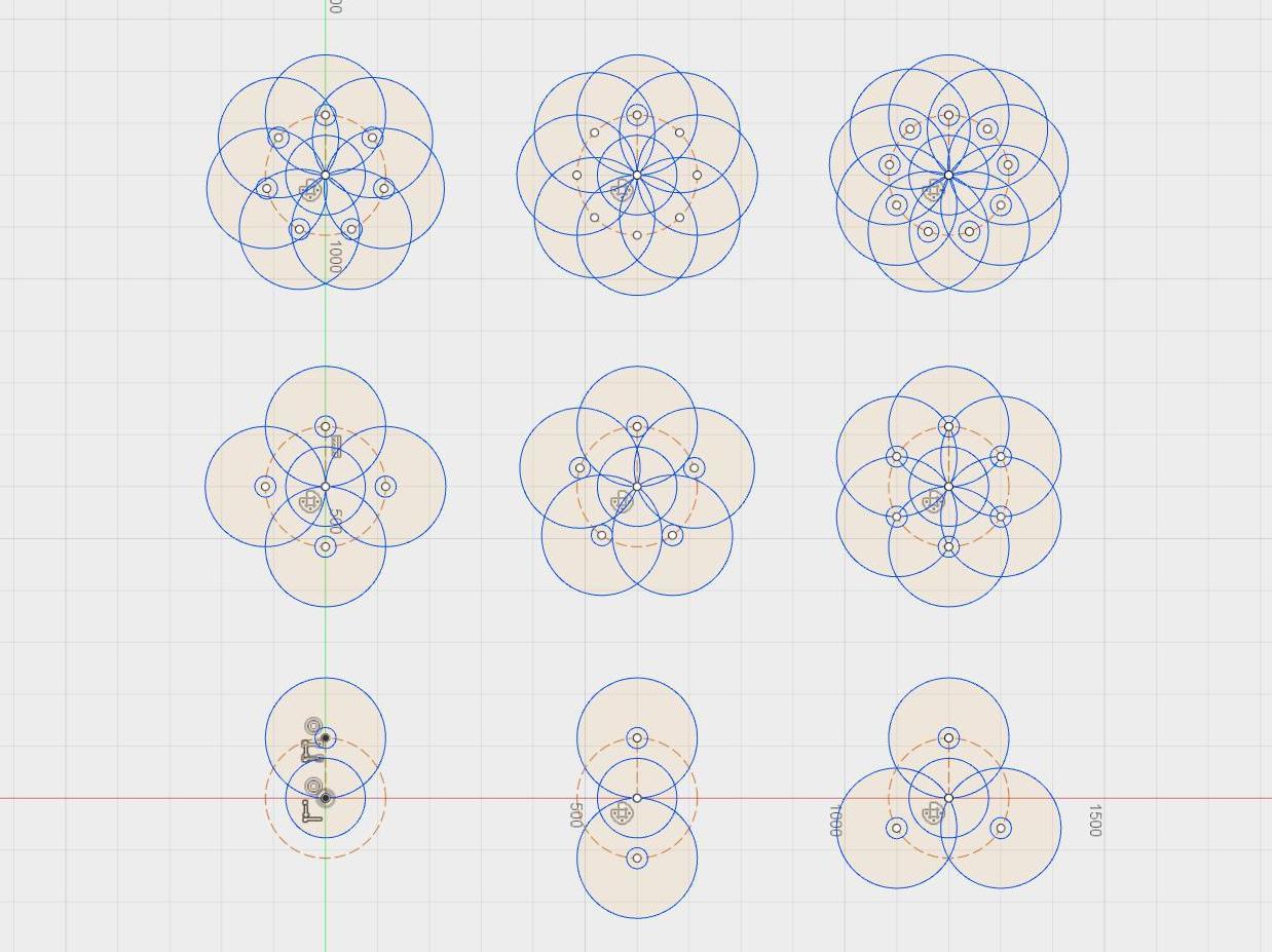
Interestingly, the number of blades, at least for a leaf that rotates around a pin, is limited to 5 due to geometry. At 6, the bladesstart to interfere with the rotation point. (So, at least for now, my plans for a 7 leaf version were foiled.)
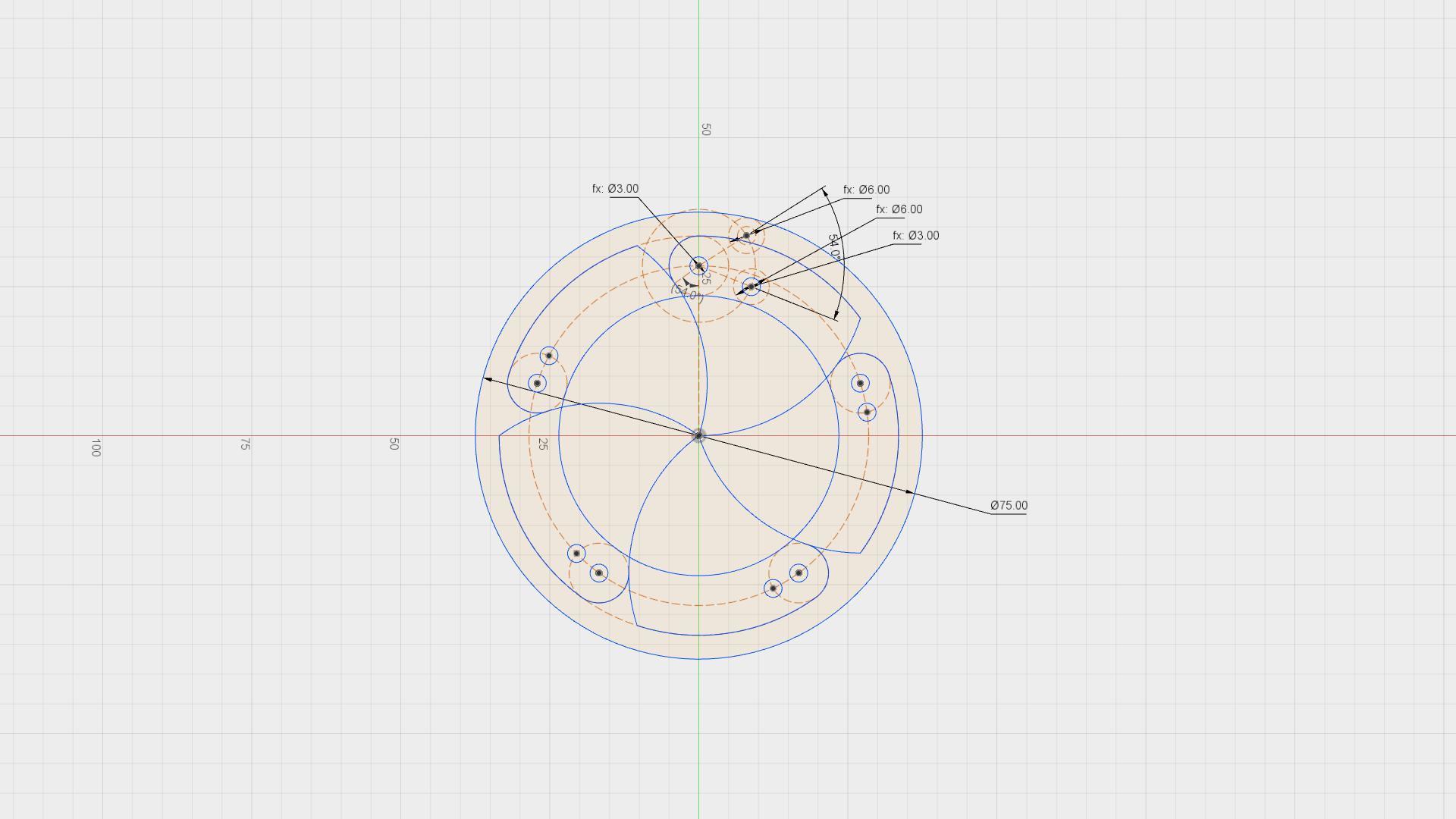
Blade Design
I thought the geometry would be more complicated, but this mechanism is mostly circular arcs. The main consideration is ensuring that the leaf can rotate into place to cover the aperture(opening), and when rotated open, don’t obscure the aperture. There is flexibility in the shape of the portion of the that is normally covered by the portion that is
Ring / Mechanism Design
There are a variety of different ways of rotating the blades, mostly involving transferring motion from an outer rotating ring to the blades using slots or rotating links. I also considered designing the outer ring as an internal ring gear and using that to drive a gear attached to the blade. Alternatively, I also found a design that used gears on the blades and a drive belt. For initial simplicity, I chose to have the blade rotate around a fixed pin, and use a pin-slot mechanism to drive the rotation.
3D Printing Design Considerations
I applied a 0.25 mm tolerance to the slots and the mating surfaces of the blades, based on similar testing I had done on the Tinkerine. For the first prototype, I wanted to print something quickly, so I limited the component height to 1.5 mm.
3D Printing
I printed the parts on the Tinkerine using an aluminum PLA filament and the following settings:
Layer height: 0.2
Walls: 2
Fill: 18
Speed: 70
Temperature: 220
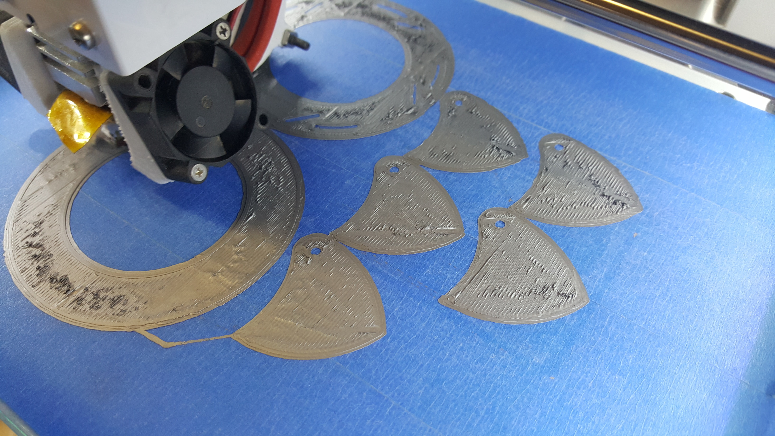
The first layers were a little rough, which I suspect is due to temperature choice. Thankfully it evened out, and finished in just over an hour.
Assembly
I prepared the parts for assembly by first removing the brim. In hindsight, these parts were probably large enough to not require a brim and this would have saved significant time. Cleaning the brim on the inside of the holes and the slots was particularly challenging.
I sanded the faces of all blades, the ring, and the base and cleaned up any moving edges. I then printed small caps for the pins and super glued them in place.
Testing
It worked! And it’s pretty fun to play with.
The biggest challenge is finding a convenient way to hold it. It is quite thin, and the blades extend out when it is opened, making it challenging to find a good place to put your fingers. There is also considerable friction between the blades and the ring and the blades and the base, which increases greatly if you try to sandwich the layers to grab it. I ended up adding some material on the back surface to make it easier to actuate.
The tolerance on the blade rotation pins was nearly perfect. The tolerance on the slots was a little too much, introducing a bit of slop into the rotation. Finally, the tolerance on the blade edges was also too much, introducing a noticeable gap when the iris is closed.
Next Steps
- Improve usability - make it easier to hold and reduce the friction during actuation.
- Design a more robust method to assemble and keep the ring attached to the base.
- Optimize tolerances or assembly method so that the blades fully close.
- Design a variant that can be actuated by a servo or motor