I will be opening the space this Thursday evening to continue this group build. @Majicj and I will be working on getting the bootloader and firmware installed on our boards, and hopefully running the calibration routine.
Everyone else is welcome to attend no matter what stage of the build you’re at. Come and get your kit!
I’ll try to get there as well. If my new SWD programmer is working, I’ll bring it as well… it’s… special… (in that awesome shiney sort of way)
I started looking at the given firmware and I really don’t like it. I’m working on a kalman filter based approach that’ll use field-oriented control (it appears to be using this, kinda). Not ready yet but it’s high on my priority list so I should have it done in bit here.
To a certain degree. I wouldn’t trust the CPU to stay on or even the magnetic sensor but the SOT-23’s would have no issue. Even the sensor may stay on if there aren’t any movements or vibrations.
There are also glues specially made for this as doing double-sided boards is pretty common. I’m not quite sure where to get it or what it’s called though; maybe someone else has more info?
A long time ago my boss at one place mentioned that a reflow oven manufacturer used to take a brand new oven to trade shows and cook pizzas all day on it. Great gimmick and people loved it, but that was a brand new oven as the gasses put off by reflowing solder aren’t exactly food-safe.
As a fun note, the reflow oven makes an ideal pizza oven; super-fast, high energy, perfect top/bottom temperature, and the pizza comes out at just the perfect temperature to eat right away due to the cooldown cycle on them. - don’t try this at home…
I havn’t run the over yet so still not sure the full procedure but I was thinking last night that I’d put all the small components on top that are near the same height off the surface then bake it. Then do the bottom side same way. Then back to the top.
I just wasn’t sure if multiple bakings would be a good idea. As well wasn’t sure what surface the board would be resting on. If it is a flat surface then that would hold the pieces underneath to the board as they melt again.
Other reason was I thought that way I could hand solder the really large parts afterwards.
Also yeah I saw that IC oven with the pizza baking way back. I think someone asked if they had plans to create a pizzeria version Someone also suggested pizza’s during the day. IC’s at night.
I seem to remember that prior to that oven, a lot more boards were through holes. Good chance it had a lot to do with the move to smd’s
Yeah, SMD is easier/cheaper/faster to automatically assemble and solder
than through-hole.
I wouldn’t rest the board on any components, probably. I imagine the
plastic turns into the consistency of warm chocolate
What I’ve seen done is holding the PCB a couple centimetres above the tray
with spacer blocks on either side, or a metal vise, or binder clips or
something.
edit:
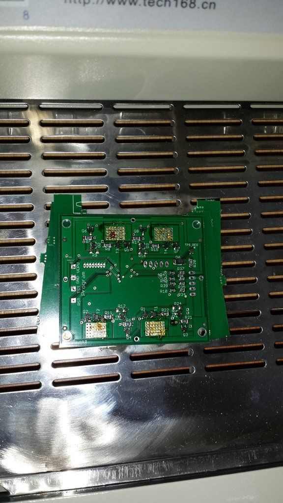
See the little scrap PCB material on either side
Just had a thought. Wonder if a piece of heat insulation ceramic underneath would also work. Just thinking it might keep the bottom side a little cooler during a reheat. Might be overkill though. Or might keep the board itself from warming up enough for a good flow.
that vibration may be caused by the channels oscillating too fast. does sort of depend on the driver but its probably around 500/hz. That’s the usual for 3d printer drivers
The vibration is caused by the PID not being tuned. I suggest lowering the ‘P’ value (proportion) as that’ll make it not overshoot as much. If you have a higher load on the shaft it’ll also lower the overshoot. Alternatively you can turn up the D variable so it limits the P and I parts, but that’s a touchy one I’ve found.
We should really set up an application that can display the error and current and can adjust the P,I and D settings easily - these things aren’t self-tuning and won’t be effective over the range of load (no load will overshoot, high load will delay a lot)… this is why PID sucks for this use; but that’s a personal opinion.
Much quieter but still some some noticeable vibration in closed loop mode.
I changed the following in Parameters.cpp
//volatile float pKp = 12; // MGJ_Issues - motor seems to vibrate so reduce proportional
//volatile float pKi = 0.50;
//volatile float pKd = 7.0;
// some guesses for new values
// note select “no line endings” in serial monitor when setting kpX and kvX values
volatile float pKp = 3; // - use “kpp3” from arduino serial monitor to change live
volatile float pKi = .05; // - use “kpi.05” from arduino serial monitor to change live
volatile float pKd = 8; // - use “kpd8” from arduino serial monitor to change live
Was looking for PID modelling software and came across an open source MATLAB tool called Octave. Very cool!