I will be there around 7:00ish…
Keep in mind I only have leaded solder and these boards are double sided…
So the second side may have to be done by hand…
There’s a lot of debate about this on the openpnp lists. The general consensus seems to be that any parts 0805 or less will remain in place with the surface tension if inverted. People seem to recommend supporting the boards by the corners in the oven.
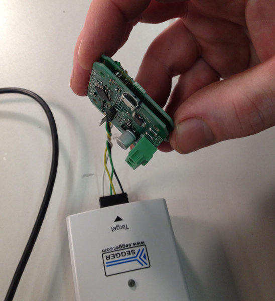
I used J-Link Commander (My J-Link is left in the locker for now - I’ll grab it in a week or two - mine’s modified to directly program with 3.3V applied and uses a custom connector)
the following sequence of commands were used in the JLink Commander interface:
connect
(Device): ATSAMD21G18
(Interface): S (for SWD)
(Speed): (for default)
To which it replied with some info about the chip ending with “Cortex-M0 identified”
then:
erase
loadbin (Absolute location of file) 0x08000000
It’ll say status ending with “O.K.”
After this you can program it using the Arduino application.
These probably aren’t the best directions but I need to go to bed and still have to drive to surrey - hope it helps someone else figure it all out too.
J-Link Commander is part of the Segger J-Link application. There are alternatives such as OpenOCD or using Atmel Studio ( Restoring Bootloader | Proper Debugging of ATSAMD21 Processors | Adafruit Learning System covers most of this)
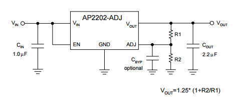
If the output from the regulator is not 3.3 you very likely have a problem somewhere. A lot of parts are 3.3 to 5.0 tolerant which may explains why smoke hasn’t escaped yet. I would look into it before applying power again just in case.
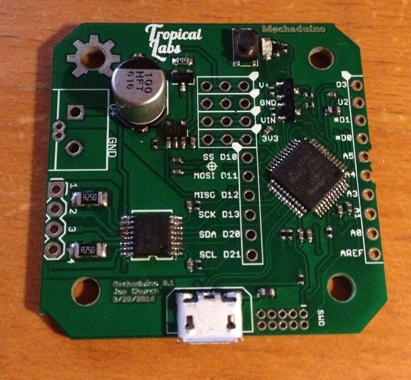
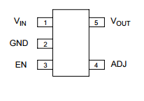
AP2202. Pin 4 is a Bypass/Adjust circuit which is currently not connected on the circuit board .
As the AP2202 needs some additional circuitry on pin 4 my guess is that the input for the bypass circuitry is floating and Vin is being passed directly through to Vout.
Sooo… careful of that magic smoke folks
Does anyone have any AP2112K-3.3’s kicking around?
Looks like the version of regulator we have is AP2202K-ADJ, which is an adjustable version. It could be replaced with an AP2112K-3.3, or AP2202K-3.3, or deadbug soldered to set the voltage. This is what I’ll probably do, if the fixed voltage versions don’t materialise. (They’re common parts, so someone might have them, or they might be in our parts bins)
So R1 and R2 will have to be deadbug soldered to the proper pins. Acceptable values could be:
R1 = 2K
R2 = 3.3K
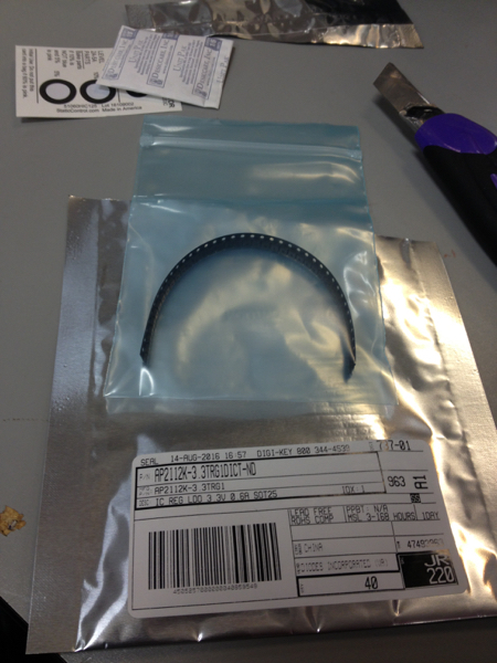
As I mentioned on slack I have 6 x AAT3221IGV-3.3-T1 that we believe are pin compatible (enable is the same polarity too). They’ll need to be picked up from my place near the PNE, am around until Wed night. 50c ea if that’s ok.
40 3.3V regulators have arrived. Replaced the regulator on my board and voltage reading is now reading 3.28v so all good.
I’ve put them in with the rest of the Mech parts in the bin. If you need your parts mailed to you leave a note here and we shall see what we can do. I’ve taken 2 so 38 left.
Total with shipping and taxes was $31.07 or 78 cents each. I don’t have time to collect cash from folks so consider making an equivalent donation to VHS.
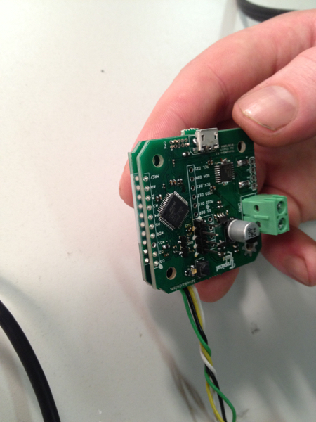
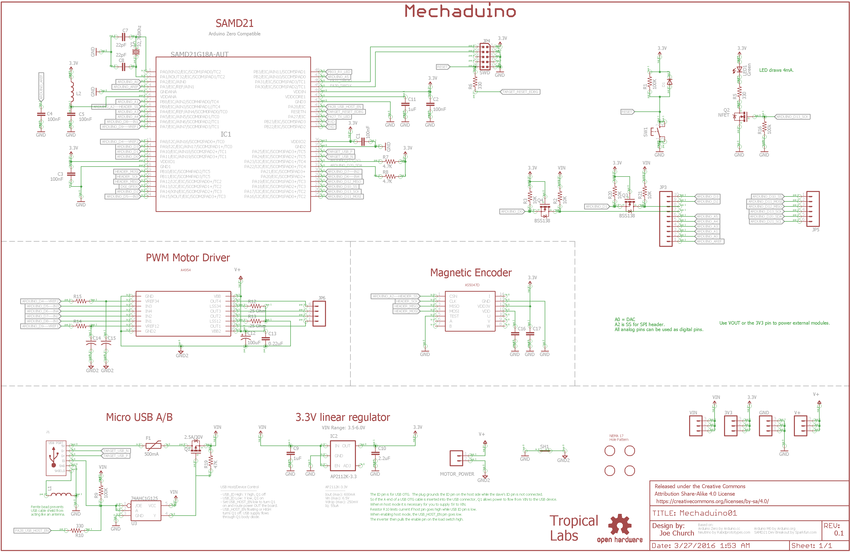
I am fairly certain that SAMD21 microprocessor on my first Mechaduino board has been fried.
The SAMD21 Data sheet says max voltage is 3.8V and it had 4.4V with previous the regulator.
Clock is getting to it. Voltage levels are now correct at 3.3V. There was no response from running the standard Blinky sketch (updated with the correct pin to match the board). I’ve verified that the board LED is working by shorting source to drain on Q2. Also tried a few digital writes to a few other pins with no results showing on the scope.
So today I’ve assembled my second board which brings me to Bootloaderz!
I’m guessing the Bus Pirate can do it. We have one at VHS.
I am wondering if anyone has a bit of time to walk me through this? I’d like to learn more about this.
@LoialOtter left his bootloader last week in the Mechaduino locker. It’s connected to the hacky pogopin setup I made, which has pins that can be pressed into the corresponding unpopulated holes on your board. I believe with that you can simply program the bootloader using the Arduino IDE. You will need to download board support for Arduino Zero if you haven’t done so already.
That’s too bad about your first board. Mine came to life and I could communicate with it over serial. It did appear a bit flakey though which could be the same voltage issue.
Thanks for purchasing new regulators. I’ve added this to my list of small issues that I plan to send back to the Mechaduino folks to update their BOM.