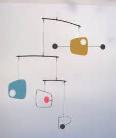
I want to make some laser-cut hanging mobiles for gifts. I thought I would create all the vector art in Illustrator, cut it on the laser, finish the wood and string it together with fishing line. Here are some examples:
But in my opinion, a real hanging mobile has multiple levels of recursion, like this:
The more I’ve thought about it though, the more I realize the workflow is actually kind of complicated. In order to ensure that all the hanging objects hang straight, they have to be attached directly above their centre of mass. Similarly, the balancing beams need to be balanced, which is difficult if the objects aren’t all the same mass. This either requires experimenting and adjustment, or using software that can do some math or even a physical simulation.
I asked about this on Slack and a handful of other people expressed interest in this project. So here’s a thread. Let’s figure out this workflow together.
The math seems like it should be pretty straight forward - the weights on either end of a beam define where its pivot point/fulcrum will be, so I’d just go bottom-up starting with whatever weights you want to use for lowest tier.
i.e.:
let A be the mass on LHS of the beam.
let B be the mass on the RHS of the beam.
let C be the fulcrum’s location (0…1) along the beam from A (0) to B (1)
C = B / (A+B)
Then use the mass of that node as the A/B for the next node up the chain and repeat.
Despite the ease of computers there still is simpler way to assemble these.
Start with the bottom beam and add your 2 items to the ends. Then tie the supporting string to the beam in the center loosely. Slide the string along the beam til its balanced and then tie it tight at that point.
That piece can now be tied to the beam above with its pair and the cycle repeated.
I agree that the bottom-up approach makes sense since each pivot should be balanced.
Note that you may also need to factor in the mass of the beam itself, especially if you are using a heavier rod or dowel. Things get more interesting still if your beam doesn’t have a constant cross-section.
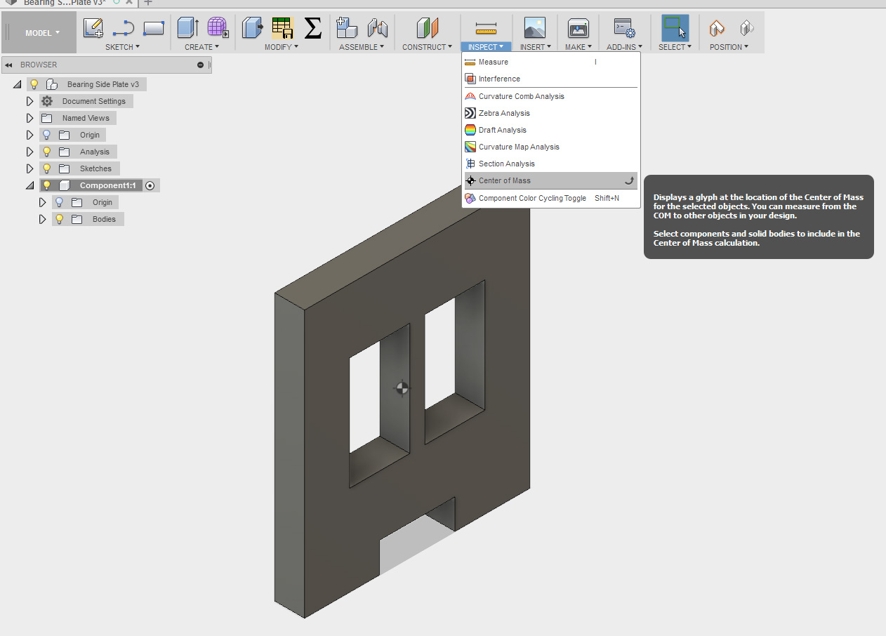
Someone (@Jarrett?) found a script for Fusion 360 that adds a construction point at the current center of mass, but it was lost to the Slack archive when I tried to re-find it today.