I’m trying to take a cheap music keyboard and interface it with a Teensy and Audio Shield. I breadboarded an interface to sense the keyboard key presses, and it sort of worked, but changes are needed to address key ghosting/masking. This is my latest plan, and I have a few questions for those who are actually knowledgeable in electronics!
Floating pins:
Does the 74HC597 require pullup/pulldown resistors if they are monitoring switches? For pins that I don’t need to control (/RST on 74HC597, and CLKEN on 4017), can I leave them disconnected or should they always be connected to Vcc or GND?
Diodes:
The keyboard electrically resembles a key matrix and is interfaced through the 15x1 header. The first 7 pins are for row (_oct_ave) selection, and the following 8 pins are for column (key) sensing. I will need to modify the circuit to incorporate diodes at every key, to prevent key ghosting/masking. I’d appreciate any advice on what sort of diodes I should use. I’m confident that I can cut traces and SMD solder the diodes, but I want to make sure I’m using the right ones!
Vcc:
For the circuit below, what should I run Vcc at? I have easy access to 5V and 3.3V (through the Teensy’s onboard regulator), and all chips run within that range. Teensy’s pins are 5V tolerant. I will eventually protoboard this; I don’t intend to build a PCB, this is mostly practice with CircuitMaker and to help convey to others what my plan is. Criticism/suggestions beyond what I’ve asked are certainly welcome, but I’m also not needing the diagrams to be perfect.
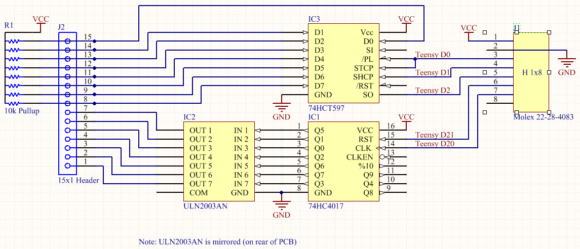
J1 - Connects to Teensy (Arduino). J2 - Connects to 44-key keyboard circuit. 74HC4017 - Pulls high one of its output pins at a time, and cycles through each of them. ULN2003AN - Transistor array to provide more current to the multiplexing circuit. The 4017 on its own can’t handle multiple pulldown resistors. This also (supposedly) inverts the logic, so that an input HIGH creates a LOW output, and an input LOW turns the output to high impedance. 74HCT597 - Parallel to serial shift register, for sensing each key in an _oct_ave. 10kohm Resistor Array - As pullup resistors for the 597 inputs, because I think I need them.
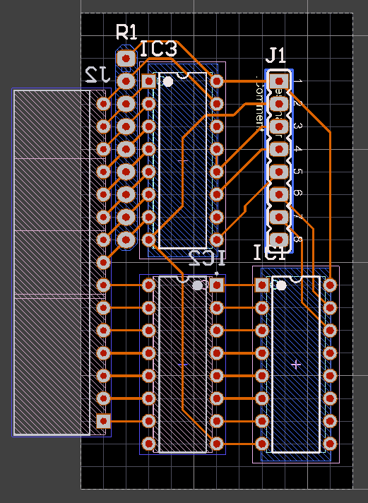
ULN2003AN is mounted from the reverse so that the pins line up well.
The white female header is on the bottom of the board because I haven’t figured out how to mirror renderings easily.
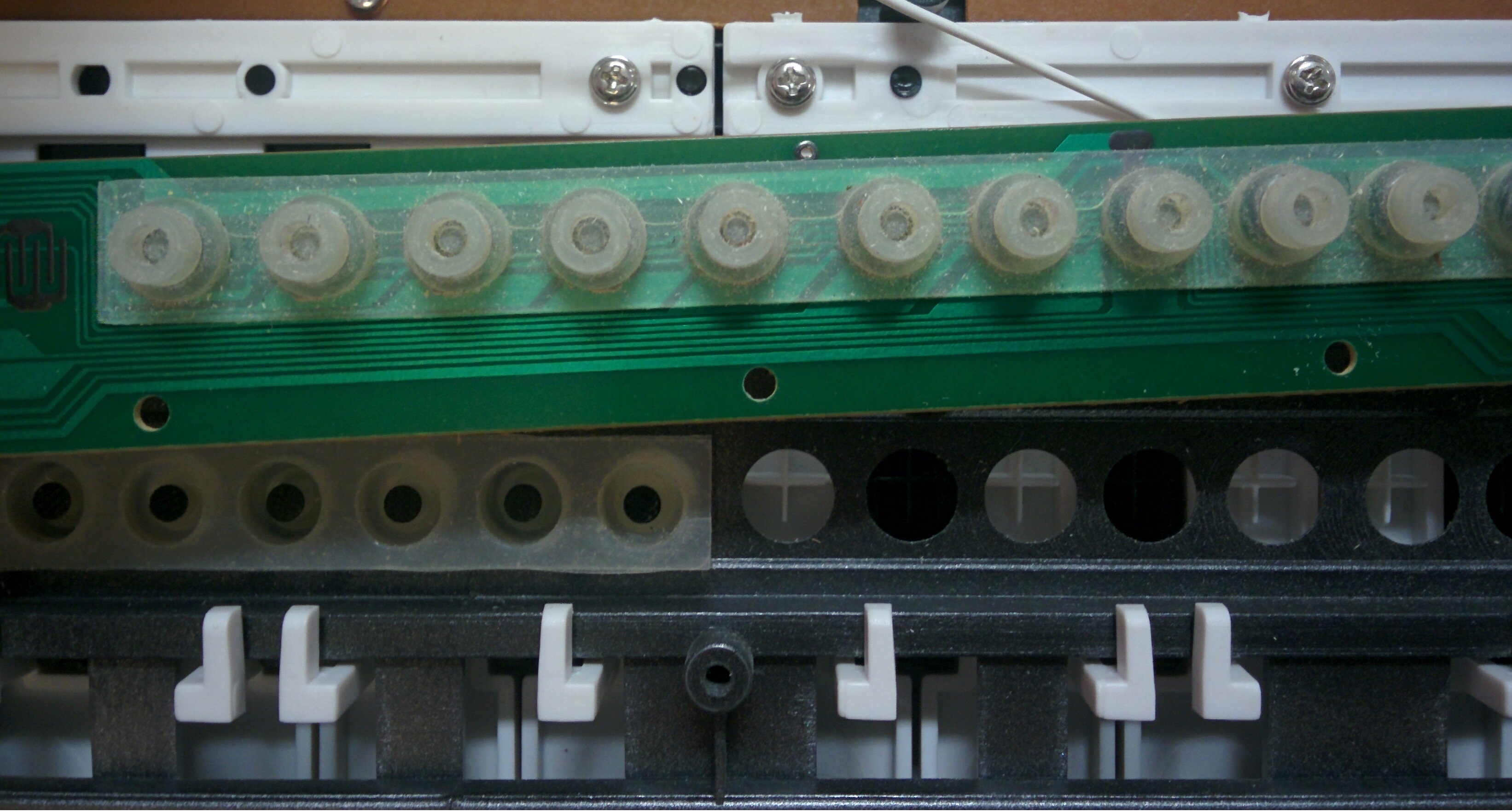
Update regarding diodes, I took the keyboard circuit off again to look at it, and it’ll actually be a lot more difficult than I recalled to place diodes where they won’t get in the way. Here is the full circuit:
Carefully scraping off the green solder mask along the traces one can
solder smd diodes across a cut of the appropriate trace
SOD-923 packages are available for the 1N4148 diodes
Wow, SOD-923 packages are tiny! 0.4mm tall. You’re right, those would probably fit, as they’d be pressed up against the rubber and that’s probably fine.
I did test and confirm today that the ULN2003AN outputs are normally high impedance, and become a current since (output low) when a high voltage is applied to the input.
Key Ghosting is not the problem you need to solve because you will be pressing multiple keys on MUSIC keyboard. Debouncing is the problem for most of the switches so each key need to be properly debounced.
I am not sure what is the goal of the project? I assume you want to make an improvement or better version of keyboard comparable to those that are available for sale right now. What is going to make your version better? Debouncing, super fast and adjustable response times, pressure sensitivity or something else?
I would start from adding separate microcontroller for each button, iterate on this single button and then connect these button/boards over some kind of serial link to main board and then connect main board to PC over USB.
Debouncing isn’t very hard to deal with in software, and key ghosting is most definitely the problem I need to solve here. Feel free to look at the photos of the circuit board and the link I posted regarding key ghosting. The only unclear part about the circuit board is that there are a few jumper wires on the other side. If you pair off each solder blob with the nearest other solder blob, those are all of the jumper connections not visible. With that information, you can work out that it’s like a standard row-column button matrix with the rows lined up end-to-end. Without diodes on this sort of matrix, you will get key ghosting.
The goal of the project is to make a keyboard synthesizer that I can make sound however I want. It might do some things better than most keyboards, but it’s mostly experimental, not really intended to compete with existing products.
Right … what I meant to say is that you should not try to prevent key ghosting in your keyboard - you need to be able to press adjacent keys at the same time. Or I don’t understand what music keyboards do.
Thanks Tom. On Tuesday, @hectorh found some pretty small diodes for me. They are SD103AWS and the package is SOD-323. I’ve done some up on the circuit board and will hold of on the rest until I have the sensing circuit to test what I’ve done so far.
